Most neural networks tend to rely on linear, step or sigmoidal ... Key-Words: - Lossless data compression, neural network, two-stage, predictor, encoder, radial ...
Application of Generalised Regression Neural Networks in Lossless Data Compression R. LOGESWARAN Centre for Multimedia Communications, Faculty of Engineering, Multimedia University, 63100 Cyberjaya MALAYSIA
Abstract: - Neural networks are a popular technology that exploits massive parallelism and distributed storage and processing for speed and error tolerance. Most neural networks tend to rely on linear, step or sigmoidal activation functions for decision making. The generalised regression neural network (GRNN) is a radial basis network (RBN) which uses the Gaussian activation function in its processing element (PE). This paper proposes the use of the GRNN for lossless data compression. It is applied in the first stage of the lossless twostage predictor-encoder scheme. Three different approaches using the GRNN are proposed. Batch training with different block sizes is applied to each approach. Two popular encoders, namely arithmetic coding and Huffman coding, are used in the second stage. The performance of the proposed single- and two-stage schemes are evaluated in terms of the compression ratios achieved for telemetry data test files of different sizes and distributions. It is shown that the compression performance of the GRNN schemes is better than existing implementations using the finite impulse response (FIR) and adaptive normalised least mean squares (NLMS) filters, as well as an implementation using a recurrent neural network. Key-Words: - Lossless data compression, neural network, two-stage, predictor, encoder, radial basis.
1 Introduction Inherent parallelism, distributed, error tolerance, and the ability to learn, adapt and generalise input patterns, are some of the characteristics of neural networks which gives them the added edge over classical technology. These characteristics are sought after in the area of data compression, especially when dealing with real-time applications and remote equipment, which make repair and maintenance costly. Lossless data compression assumes importance when dealing with data that is sensitive to error, such as in high definition medical images and in satellite telemetry. In recent years, several types of classical and neural network schemes have been successfully applied in lossless data compression [1]-[3]. The neural schemes generally employ the use of the step (hardlimiter), linear and sigmoidal function(s) in their processing elements (PE) or the hidden and output layers. An alternative approach is the use of a radial basis function in the decision nodes. Radial basis nodes produce identical outputs for inputs with equal distance from the centre, acting as a detector of the input. The most common of these functions is the Gaussian distribution. Radial basis networks (RBN) [4] can be designed in a fraction of the time
taken to train standard feedforward networks [5], a significant advantage in real-time applications. Several implementation schemes of a RBN, known as the generalised regression neural network (GRNN), are proposed in this paper.
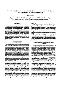
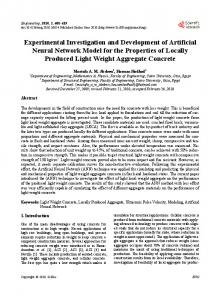
2 GRNN Models The GRNN [6] is a two-layer feedforward network (by convention, the input layer is not mentioned), consisting of a radial basis hidden layer and a special linear output layer, as shown in Fig. 1 with the activation (transfer) functions in Fig. 2. The activation level of the hidden layer is determined by f rb in (1), using the net input, N, in (2).
f rb = e − N
2
(1) N = ( || W – X || ) b (2) where f rb (• ) = radial basis activation function N = net input to the activation function W = weight vector of the PE containing weights w1 , w2 … wp X = input vector of the PE containing inputs X1 , X2 … Xp b = bias of the PE
The nodes in the output layer form a linear combination of the basis (kernel) functions computed by the hidden units, producing the overall output (decision) of the network at each iteration. Input
Radial Basis Hidden Layer
Special Output Linear Layer
w1 w2 . . . wp W2
X1 W1 +
N1
X
X2
||W–X || −
: Xp
×
Y1
N2
f rb
×
N3
f lin
Y2
b
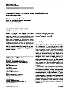
such that a number of past samples, say p, are used to predict the current sample. The p th -order GRNNP derives an approximation function of the input, F, during its training phase using a training window. The input values are then predicted by using F, as shown in (3).
Xˆ n
= FGRNNP (Xn-1 , Xn-2 , …, Xn-p)
where FGRNNP = approximation function derived by the GRNNP ˆ = predicted nth value Xn Xn = nth input value
Xn
Fig. 1 : GRNN structure with p inputs
(3)
Z-1
Xn-1
-1
Xn-2
^
Z
f rb (n)
f lin (n)
1.0
GRNN
Xn +
Σ
Yn
− Z-1
+1.0
Xn-p
n
0.5 0.0
-0.833
n
+0.833
-1.0
(a) Radial basis (rb)
Fig. 4 : GRNN Predictor (GRNNP) model (b) linear (lin)
Fig. 2 : Activation functions of the (a) hidden and (b) output layers of the GRNN For lossless data compression, the well-known two-stage scheme, shown in Fig. 3 [1], is chosen. In this scheme, the first stage is used to predict the current input, Xn . The residue, rn , is generated by taking the difference between Xn and the predicted input. The encoder in the second stage is used to compress the residue before transmission. The GRNN is to be used in the first, whilst lossless arithmetic coding is used as the encoder. Three approaches of adapting the GRNN for the first stage are attempted. Each approach has different processing and storage requirements. These approaches (models) are detailed below. Input,
Xn
X
Residue,
Lossless Predictor
Yn
Output,
Lossless Encoder
On
Fig. 3 : Two-stage compression scheme
2.1 GRNN Predictor (GRNNP) The first approach is to use the GRNN as a predictor, shown in Fig. 4. The network is set up
2.2 GRNN Approximator (GRNNA) To realise the usual application of the GRNN as a function approximator, the second approach uses samples taken at regular intervals throughout the data, in designing the network. These samples are used as the target (expected) values. Fig. 5 shows the structure of the GRNNA.
Xn Xi Xi-I
X
GRNN
Xˆ n +
Σ
Yn
−
Xi-I(p-1) j = final sample in training window of current block I = size of an interval between samples p = no. of input nodes n = number of current sample (j-pI +1 < n < j)
Fig. 5 : GRNN Approximator (GRNNA) / GRNN Estimator (GRNNE) model Only the p inputs at intervals I of the training block are used in setting up the network. The approximation process for the remaining input data is simplified as (4).
Xˆ n = FGRNNP ( n)
(4)
where FGRNNA = approximation function of GRNNA
Xˆ n = predicted n th value n
= number of the input currently being approximated
The remaining input values are not used in the approximation process, except in the generation of the residues. This approach enables the GRNNA to use a larger range of the input for function approximation. For better approximation, the input should be preprocessed by a function analyser to identify training samples that are most representative of the input pattern. The additional overheads incurred are costly in terms of time and processing power, and make it impractical for real-time applications.
2.3 GRNN Estimator (GRNNE)
block1
block2
prediction process
sample .no. 1 p
prediction process
0.2 S B
SB
1.2 S B
2 SB
The GRNN is trained at the design stage, where only one set of input values is presented to the network at a time. For the GRNNP, this is done numerous times with different p consecutive input values within the training window each time. The trained GRNN is set up as an approximation function, F, of the input. Adjustment of the weights and biases is done in a way that minimises the mean absolute error (MAE) between values approximated using F and the actual training sample values.
prediction process
2.2 S B
3 Training Schemes
block3
3 SB
The GRNNE is a compromise between compression and processing performance of the GRNNA. The structure of the GRNNE is similar to that of the GRNNA. The difference is that samples are taken at intervals on a subset of the input block, namely the training window, and not of the entire block. The value of the interval, I, in (4) would be of lesser magnitude than the one used for the GRNNA. This provides the design stage more distributed samples for function approximation than the GRNNP, while not requiring that the entire input block be buffered as in the GRNNA implementation. The approximated function is projected across the input block. This scheme assumes that intrablock input pattern variation is small, so that the projected function is able to perform well in estimating the input values.
Training schemes may be varied in terms of the size of data sets, S B , presented to the network. In the single-block (SB) training scheme, the entire input file is treated as one continuous block. A training window of the first 500 samples is used for training, according to the different approaches. The remaining samples are then predicted, approximated or estimated depending on the model used. The residues are generated from the difference between these values and the actual values. To enable semiadaptive training, whilst and minimising buffer requirements and processing time, a batch training method was also implemented. S B of 50, 500, 1000, 1500, 2000 and 2500 samples per block are tested. In this method, a training window of 20% of the block size is used. Identical first-stage networks and encoders exists at the transmitter and receiver ends. It is assumed that this criteria ensures that any losses incurred at the transmitter is identically incurred at the receiver, so the restored value with the residue is identical to the source input data. The networks would also need to be trained in the same manner to achieve losslessness. In order to maximise compression, the coefficients of the trained network is transmitted to set the receiver network up, followed by the residues of the first block. The magnitude of the residues transmitted is significantly lower than the original input values. For subsequent blocks, the training data is predicted / approximated / estimated using the previous block’s network and the residues are sent. Fig. 6 shows the general block-adaptive training and prediction stages of the input stream at the transmitter.
Training process
Fig. 6 : Batch-training process for the GRNN Training occurs at both ends. Since training takes identical amount of time, the transmitter and receiver would be synchronised (disregarding the initial delay in setting up the first block, and assuming that the residue generation related processes take the same amount of time as the
restoration process, and that transmission time is constant and negligible). As such, both networks would theoretically be working at a constant rate, enabling real-time implementation. The networks are re-trained for each block, changing F. Initialisation of the hidden layer is done using unsupervised learning through algorithms such as the “k-means clustering algorithm” [7]. Fast initialisation of the output layer may be done via optimised methods such as the Nguyen-Widrow algorithm [8]. Supervised backpropagation may then be used in fine-tuning the two-layer network [9]. In the event when random numbers are used for initialisation, the same seed must be used at both networks, thus the sequence of pseudo-random numbers generated would be the same.
4 Configurations Neural network configurations are done with respect to topological and neurodynamic set up. In the case of the GRNN, the number of layers and activation functions are predetermined. Only one output PE is used as only one value is approximated at each iteration of the algorithm. The weights are determined automatically during training. The bias allows the sensitivity of the node to be adjusted. It is set using (5) such that for a range -NSPREAD ≤ N ≤ +NSPREAD , the output of the radial basis would satisfy 0.5 ≤ frb (N) ≤ 1.0. The constant NSPREAD should be chosen such that it is larger than adjacent input values, to allow the PE to respond strongly to overlapping active regions of the input space and allowing the network to function smoother, resulting in better generalisation of input vectors. However, NSPREAD must be smaller than the input space so that each PE does not effectively respond to the same large area of input. b=
log e (0. 5) N SPREAD
= 0. 8326 / N SPREAD
(5)
The GRNN has an equal number of hidden layer PE and input nodes. The optimum number of input nodes is determined empirically. Tables 1 and 2 give the results obtained. The results are in terms of compression ratio (CR), given by the size ratio of the original source file over the compressed file. The residues are transmitted / stored using a set number of bits, t, determined empirically. In the case that the magnitude of the residue exceeds the t-bit representation, the actual input value would be transmitted in the original s bits, preceded with a t-
bit flag. The compressed file includes all the transmitted information, including network set up information and flags. Only a limited number of test files were used at this stage, so as not to ‘over-train’ the networks and restrict their ability to generalise input patterns. The three files chosen were those that best represented the distribution of the six telemetry test data files used in the performance evaluation in the next section. Table 1 : CR obtained by GRNNP with different number of input nodes for the 3 test files Test File Number of input nodes (Size, bytes) 1 2 3 4 5 10 Td3 (139571) 3.54 3.55 3.54 3.54 3.55 3.55 Td4 (55365) 2.26 2.26 2.26 2.26 2.26 2.26 Td6 (184774) 2.21 2.20 2.21 2.20 2.21 2.20 Average 2.67 2.67 2.67 2.67 2.67 2.67 Table 2: Average CR obtained by GRNNA and GRNNE for different number of input nodes GRNN Number of input nodes model 2 5 10 15 20 2.92 2.56 2.92 2.77 2.74 GRNNA 2.92 2.94 2.92 2.92 2.86 GRNNE From the results in Table 1, it is observed that the average CR obtained for all configurations of is the same (to two decimal places). Analysing the results obtained for each test file, it is noticed that the GRNNP with 5 inputs achieved the highest CR in all the files. This 5th -order predictor is chosen. In Table 2, the maximum CR for GRNNA is achieved for the 2nd -order and 10th -order networks. The 10-10-10 (10 inputs, 10 hidden nodes and 10 output) configuration is chosen as the additional nodes would be useful in producing a better approximation function. The 2-node combination performed well as part of the telemetry data contains a linear parameter that was well approximated by the linear function approximated using 2 nodes. In the case of the GRNNE, the 5-5-5 configuration is selected as it produced the best.
5 Performance Evaluation Using the chosen GRNN configurations, the performance of the GRNN networks is evaluated for each of the training schemes. Results, in terms of the CR achieved for the first stage, using only the GRNN with the residue optimisation is given in Table 3. These values represent the average
performance of the GRNN models over the six telemetry data files. Simulation of the neural networks is done on a serial machine, and as such processing times of the algorithms is unavailable. Table 3 : Average CR achieved by the GRNN models in the first stage for different block sizes GRNN Block size (samples per block) model 50 500 1000 1500 2000 2500 SB GRNNP 6.81 3.51 3.24 3.56 3.01 2.85 3.17 GRNNA 5.68 3.09 2.94 2.79 2.86 2.83 2.94 GRNNE 5.65 4.30 3.01 2.84 2.81 2.98 2.91 From the results in Table 3, it is found that the best performance for all the three models is achieved with the smallest block size of 50 samples per block. This is as expected since the approximation function derived would be a closer representation to the actual distribution across a smaller span of the input. An interesting result to note is that although the approach used for the GRNNP is unconventional, with regards to designing a GRNN, it is found that this network produced better results than the other two approaches in almost all the training schemes. On further investigation, it was realised that in order to implement this unconventional scheme, the simulation adapted the architecture of the GRNNP by changing the number of hidden layer PE. The number used was equal to the number of input patterns presented to the network (i.e. S B – p), so the actual architecture used for the result achieved with S B 50 was 5-45-1. With a larger network of more PE, the GRNNP was able to better predict the input and produce smaller residues. It is also interesting to note that the GRNNA did not perform as well as expected. It is likely that the intervals used for sampling were unable to capture the significant patterns in the data. In general, as expected, the GRNNE achieved the lowest CR. It did, however, manage to outperform the other two networks for block sizes of 500 and 2500, and would be recommended in such situations when buffer space is costly. The GRNN is incorporated into the two-stage scheme by pairing GRNN models with a popular encoder, namely arithmetic coding (AC). The results achieved by the new two-stage schemes are given in Table 4. Again, it is observed that the GRNNP maintains the best compression performance. The way the encoders handle different residue patterns produced by the first-stage influences the overall results [10]. For instance, the best performance for block size 2000 in the two-stage scheme uses the GRNNA, not the GRNNE. To
illustrate the influence of the encoder on the twostage scheme further, two-stage schemes of the GRNN with Huffman coding is evaluated. From the results in Table 5, it is noticeable that the performance of certain two-stage schemes involving GRNNE degrades to lower CR than the results of the single-stage scheme in Table 3. This indicates that it is possible for data expansion to occur by incorporating the second stage, as observed in the case of some files using the GRNNE-HC combination for S B of 1000, 1500, 2000 and 2500. Table 4 : Average CR achieved by the GRNN in the two-stage schemes with arithmetic coding (AC) GRNNBlock size (samples per block) AC 50 500 1000 1500 2000 2500 SB GRNNP 9.27 4.22 3.81 4.01 3.53 3.37 3.45 GRNNA 8.57 4.11 3.75 3.61 3.60 3.78 3.31 GRNNE 8.43 5.07 4.11 3.96 3.83 3.85 3.26 Table 5 : Average CR achieved by the GRNN in the two-stage schemes with Huffman coding (HC) GRNNBlock size (samples per block) HC 50 500 1000 1500 2000 2500 SB GRNNP 8.70 4.11 3.71 3.91 3.45 3.29 3.38 GRNNA 8.15 4.00 3.66 3.55 3.52 3.68 3.24 GRNNE 8.02 4.90 2.97 2.81 2.77 2.93 3.19 In order to provide relative performance comparison, existing two-stage may be used [1]. A fixed 5th -order finite impulse response (FIR) filter using the coefficients described by (6), and an adaptive normalised least mean squares (NLMS) predictor are applied to the first stage.
Xˆ n = 4xn−1 − 7xn−2 + 7xn−3 − 4xn−4 + xn−5
(6)
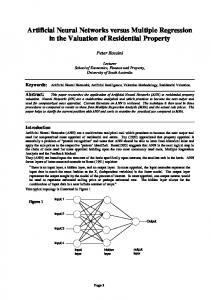
The compression performance of these linear predictors and GRNN models (for block size 50) in the single- and two-stage schemes on the test data files is given in Fig. 7. It is shown that all three neural GRNN models perform significantly better than the linear models in the single- and two-stage schemes. To compare against different neural networks, a 2nd -order multi-layer feedforward network (MLFN) and a 5th -order recurrent Elman network (EN) were implemented and the results are incorporated in Fig. 5. The MLFN was set up with a hidden linear node and a sigmoidal output node. The recurrent was also set up with the same activation functions, but with two hidden nodes. Training was undertaken for SB of 1000 and 50 for MLFN and EN, respectively. The
GRNN combinations were found to achieve better results than the EN, although the well-known MLFN, achieved the highest CR compared to the rest of schemes. CR
predictor
predictor-AC
predictor-HC
16 14 12 10 8 6 4 2 0 FIR
NLMS
GRNNP GRNNA GRNNE
MLFN
EN
Predictor
Fig. 7 : Best average CR achieved by linear and neural models in single- and two-stage schemes
can be designed quickly. The performance of this approach was the lower than the others since the stretching of the approximation function was a weak representation of the input pattern of the entire block. All three GRNN models were shown to achieve better compression performance than existing linear schemes using the FIR, NLMS and certain neural network algorithms. It is also shown that the choice of second-stage encoder is important in the twostage schemes, as data expansion may occur if the encoder chosen is unsuited to compressing certain patterns in the first-stage residue stream.
References: [1] J.W. McCoy, N. Magotra and S. Stearns, Lossless [2]
6 Conclusions The GRNN generally requires more PE than standard feedforward networks (such as the MLFN), but can be designed in a fraction of the time taken to train the other networks. This gives it an advantage in terms of real-time applications. In order to minimise complexity and processing requirements, only small networks were implemented. All results quoted are simulation based, and given in terms of compression ratios achieved for a number of telemetry data files. Altogether, three different approaches of the GRNN in nine schemes are discussed, in both single- and two-stage implementations. The GRNNP functions as a predictor using a number of past values to predict the current value. Iterative training is done by redesigning the network a number of times within a predefined training window (20% of the training block, or 500 samples in the SB scheme). This approach is slower than the others, but was capable of producing the highest compression performance with the telemetry data. The GRNNA functions as an approximator by sampling the entire training block at regular intervals. In order to improve performance of this approach, more PE and/or function analyser is required to identify significant patterns in the inputs. A large buffer of size S B is required as the entire training block is buffered during the design stage. One-shot design, however, allows the network to be designed very quickly. The GRNNE estimates the input by projecting the approximation function derived using the training window, across the training block. It uses a smaller buffer (0.2 SB ) and
[3]
[4]
[5]
[6]
[7] [8]
[9]
[10]
Predictive Coding, IEEE Midwest Symposium on Circuits and Systems, 1995, pp. 927-930. R. Logeswaran and C. Eswaran, Lossless Data Compression using a Recurrent Neural Network, International Conference on Signal Processing Applications and Technology, November 1999. R. Logeswaran and C. Eswaran, Neural Network Based Lossless Coding Schemes for Telemetry Data, Proceedings of the IEEE International Geoscience and Remote Sensing Symposium 1999, Vol. 4, 1999, pp. 2057-2059. G.F. Poggio and F. Girosi, Networks for Approximation and Learning, Proceedings of the IEEE, Vol. 78, No. 9, September 1990, pp. 14811497. S. Chen, C.F.N. Cowan and P.M. Grant, Orthogonal Least Squares Learning Algorithm for Radial Basis Function Networks, IEEE Transactions on Neural Networks, Vol. 2, No. 2, March 1991, pp. 302-309. P.D. Wasserman, Advanced Methods in Neural Computing, Van Nostrand Reinhold, New York, 1993. R.O. Duda & P.E. Hart, Pattern Classification and Scene Analysis, Wiley, New York, 1973. D. Nguyen and B. Widrow, Improving the Learning Speed of 2-layer Neural Networks by Choosing Initial Values of the Adaptive Weights, International Joint Conference of Neural Networks, Vol. 3, July 1990, pp. 21-26. D.E. Rumelhart, G.E. Hinton and R.J. Williams, Learning Internal Representation by Error Propagation, Parallel Distributed Processing : Explorations in Microstructures of Cognition, Vol. 1, MIT Press, Massachusettes, 1986. R. Logeswaran and C. Eswaran, Effect of Encoders on the Performance of Lossless twostage Data Compression, IEE Electronics Letters, Vol. 35, No. 18, September 1999, pp. 1515-1516.