search for the Doppler frequency and the PRN code chip delay. ..... 7: GNSS signals in the Galileo and GPS bands (from OS SIS ICD. 2008). Table I: GPS and ..... x 10. 6. Number of Real Multiplications. S ig nal T y pe. Split-radix FFT Approach.
Journal of Global Positioning Systems (2009) Vol.8, No.2 :174-186 doi:10.5081/jgps.8.2.174
Application of Mixed-radix FFT Algorithms in Multi-band GNSS Signal Acquisition Engines Nagaraj C Shivaramaiah, Andrew G Dempster, Chris Rizos School of Surveying and Spatial Information Systems, University of New South Wales, Sydney, Australia
Abstract Due to their fast operation, Fast Fourier Transform (FFT)-based coarse signal synchronization methods are an attractive option for Global Navigation Satellite System (GNSS) receiver baseband signal processing. However, there are several reasons why the utility of FFT-based methods is dependent on understanding the trade-off between synchronization speed and the required processing power. Firstly, the new signals of the GNSS family, for instance Galileo and GPS modernization, employ longer period Pseudo Random Noise (PRN) codes and higher signal bandwidths, which demand FFTs of large transform lengths. Secondly, to gain an advantage in positioning performance, next generation receivers target multiple GNSS signals, and since each signal has its own code length (and hence a minimum sampling frequency), the receiver should accommodate FFT blocks of varying lengths. This paper discusses the requirements of FFT-based algorithms for such a multiband receiver and analyzes the application of primefactor and mixed-radix FFT algorithms. A novel way of factorizing different transform lengths into smaller transforms and then combining these smaller-point FFTs to compute the larger required FFTs is described. It is shown that the use of the proposed architecture reduces the computational load (or processor cycles) and increases the re-usability of the acquisition search engine to process different signals. Keywords: Code Acquisition, GNSS Receivers, FFT, Multi-band GNSS, FPGA
complement those of the venerable Global Positioning System (GPS). The greatest interest has been directed to the European Global Navigation Satellite System (GNSS) known as Galileo, as well as the modernization plans for GPS. These developments (and other GNSS and Regional Navigation Satellite Systems) have posed new challenges to the receiver development community, especially with regard to the baseband signal processing of multiple GNSS signals (Dempster 2007, Dempster and Hewitson 2007). In order to compute the receiver-satellite range and to demodulate the data streams, a GNSS receiver has to first synchronize with the satellite signal. The receiver has to search for the Doppler frequency and the PRN code chip delay. Signal synchronization is generally carried out in two steps: the coarse synchronization (referred to as Acquisition), and fine synchronization (called Tracking). During signal acquisition, the receiver searches for available satellites and estimates the approximate chip delay and Doppler frequency. The resolution of the coarse estimates of chip delay and Doppler frequency depends on the requirements of the succeeding tracking stage - typical values being 0.5 chips for the code delay and 500 Hz (for one millisecond coherent integration) for the Doppler frequency. The number of time cells to search depends on the code length. The number of frequency cells to search depends on the total frequency ambiguity and also on the coherent integration time. As an example, for a code length of 10230, Doppler frequency uncertainty region of ±5 KHz and an integration time of 1 ms, there will be 20460 time cells (at 0.5 chip steps) and 21 (at 500 Hz steps) frequency cells to search. Generally, search algorithms in GNSS receivers spend more of their resources (time and processing power) estimating the chip delay than the Doppler frequency (Kaplan and Hegarty 2006).
1 Introduction There has been a tremendous increase in interest in satellite-based radio navigation technologies with the announcement of designs for multiple satellite systems and new ranging signals (Rizos 2007) that will
An acquisition engine is more useful initially when the receiver is powered on, rather than during normal operation. Hence the design goal of the acquisition engine in a multi-band GNSS receiver is to have the flexibility to search any of the desired signals using as little computer
Shivaramaiah et al.: Application of Mixed-radix FFT Algorithms in Multi-band GNSS Signal Acquisition Engines 175
resource as possible. Frequency domain methods to perform the code acquisition (FFT-based methods) provide the correlation values for all the time cells at once. However, this speed-up comes at a cost of increased computational burden due to the increased FFT length. There are several schemes to reduce the computational burden by reducing the number of points required to perform the FFT (see Fig. 1). Acquisition architecture can be modified to realize the correlation with smaller subsets of the signal and the local code (Yang 2001, Sajabi 2006). Another method is to use the assistance data (Diggelen 2009) from an external source to narrow down the search space and hence to reduce the size of the FFT. This assistance can be from an internal source such as in the case when the receiver is already tracking a signal at a different frequency band (from the same satellite) that has shorter code. This paper proposes methods that fall into a third category in which the FFT itself is computed efficiently by combining smaller FFT blocks. In a multi-band GNSS receiver, the receiver has to compute several FFTs of different sizes due to the varying code lengths of different signals. Hence the receiver has to accommodate dedicated FFT blocks of varying sizes. Moreover, depending on the code length and the required chip step, the FFT block requirement may not always be a power-of-two. For example, a tripleband receiver designed to acquire GPS L1, Galileo E1, GPS L5 and GPS L2C has to have 2046, 8184, 20460 and 40920 point FFT blocks (half chip step assumed). The transform lengths that are closer to a power-of-two number can be made power-of-two, by padding zeros (Yang, 2001) and then the power-of-two FFT can be efficiently computed. In our example this operation gives 2046 → 2048 and 8184 → 8192. For the transform lengths that are far away from the power-of-two numbers, mixed radix FFTs can be used to realize the non-powerof-two FFTs (Gunawardena, 2000). However these techniques do not solve the problem of having dedicated FFT blocks of different sizes for different signals.
number of additions and subtractions compared to the direct FFT computation method. The proposed method does not depend on the acquisition architecture and hence it can be used in conjunction with the other two categories (acquisition architecture modification and assistance information) to further reduce the computational burden. Apart from the reduction in the computational complexity, the proposed method is also useful for resource sharing in a multi-band receiver. Reducing the FFT Computational Burden
Acquisition Architecture Modification e.g. • Partial Correlation • Averaging
Assistance Information Efficient FFT Implementation
• •
External (e.g. AGNSS) Internal (e.g. L1 to L5)
Fig. 1 Methods to reduce the FFT computational burden
This paper is organized as follows. Section II gives a brief overview of the FFT approach for code correlation and the FFT factorization. Section III describes the receiver model and search dimensions Section IV FFT requirements of new GNSS signals. Section V describes the proposed Mixed-radix approach along with the result of transform length factorization for the different signal types. Section VI discusses the computational complexity by comparing the standard and proposed approaches. Section VII describes the FPGA resource utilization of the proposed methods, followed by a comparison for some of the signal combinations in section VIII.
2 FFT approach for code correlation and FFT Factorization 2.1 FFT approach for code correlation
The GNSS modernization signals come with signal structures that employ different and new code lengths. Having dedicated or individual FFT blocks for all the signals becomes extremely demanding in terms of the hardware resource and the computational burden. In this paper, a novel method of factoring the required largepoint FFT lengths to common small-point building blocks is presented. The large FFTs for any signal are then computed by combining the small-point FFTs. This technique helps the receiver to eliminate the need for dedicated larger FFT blocks. It is shown that apart from reducing the resource requirements due to the employment of the small-point FFT blocks, the mixedradix method of combining the small-point FFT blocks to build the large required FFT block also reduces the
PRN code acquisition in a GNSS receiver involves correlating the received signal at baseband with all possible time-delayed versions of the local replica code and searching for the maximum value of correlation. The correlation value indicates whether proper alignment between the codes has been achieved. It is well known that the autocorrelation and power spectral density are Fourier Transform pairs and hence time delay searches for the PRN code alignment can be performed simultaneously for all time delay values using convolution according to the Wiener-Kinchine theorem (Proakis & Manolakis 2006). The process is to multiply the Fourier Transform of the received signal with the complex conjugate of the Fourier Transform of the local
Shivaramaiah et al.: Application of Mixed-radix FFT Algorithms in Multi-band GNSS Signal Acquisition Engines 176
replica code, and then perform the Inverse Fourier Transform of the product to obtain the result - which is nothing but a vector of correlation values for all possible time delays. As the sequences are periodic, this can be achieved by making use of FFTs and this technique has been proposed for GPS, with Binary-Phase Shift Keying (BPSK) signal modulation (Van Nee & Coenen 1991). Considering a sequence with period N, the autocorrelation in time domain is given by (1a) and via frequency domain by (1b), (Proakis & Manolakis 2006)
R(m) =
N −1
∑ s(n ) s (n + m)
(1a)
n =0
(1b) R = F −1 (C ( k )C * ( k )) where s and s are the received and local code plus subcarrier, C and C are the corresponding Discrete Fourier Transforms, and * is the complex conjugate operator. Fig. 2 depicts the code acquisition process using the FFT method. Note that R is a vector representing the correlation values for each time cell. To decide whether the proper alignment is achieved between the local code and the code present in the incoming signal, max (R) is tested against a threshold value. It can be seen that the parallel search using FFTs reduces the time required for code acquisition (Holmes 2007, Sajabi et al. 2006) by computing the vector R at once. In the case of the GPS L1 C/A code, N is 1023 and the transform length is larger than N, depending on the chip spacing considered for the acquisition process. As an example, the transform length used for the UNSW NAMURU GPS receiver (Mumford et al. 2006), with sampling frequency 5.714 MHz, will require FFTs of length 5714 to process one millisecond of signal. Several methods exist (Sajabi et al. 2006, Qaisar et al. 2008, Starzyk & Zhu 2001) to reduce the effective transform length. These methods exploit the fact that during acquisition it is sufficient if both the codes are aligned within one half of a chip, which in turn reduces the transform length to twice that of the code length (with 0.5 chip spacing), 2046 in this case. Binary Offset Carrier (BOC) modulation scheme used in some of the new signals may require smaller chip spacing to avoid the correlation loss (De Wilde et al. 2006). In the light of these re-sampling methods, the number of points in the FFT is proportional to the inverse of chip spacing and does not depend on the sampling frequency. Acquisition engines that use the FFT approach for the code correlation are able to search all the shifts of the entire code length at once, which means that the number of searches in the code delay dimension is unity. The
Base-band signal s(n)
N-1
( | |2 )
FFT -1
FFT
∑(.)
Choose max
0
FFT*
s(n+m)
Fig. 2: FFT method of code acquisition in GNSS receivers
hardware resource consumed by a FFT-based acquisition method is higher than that of a single correlator which searches for one code shift at a time. Hence the aim of the fast acquisition search engines is to make use of a larger amount of hardware resources for a shorter amount of time, which often results in energy benefits compared to the single cell search engines. For this reason, the hardware used in an acquisition engine is not readily suitable for the signal tracking process which requires search across only one chip (which may involve more than one correlators depending on the tracking architecture, but much less than the number of cells to search during acquisition). 2.1.2 Factorization of the FFT Transform Lengths This section briefly describes the prime factor and Mixed-radix approaches. Detailed descriptions of the prime factor and Mixed-radix algorithms can be found in (Smith 1995) and citations therein. Prime-factor FFT algorithm The basic idea is to factor N (for an N-Point FFT) into two or more relatively prime numbers, implement the small-point building blocks, and combine them to obtain the final result. Hence prime factor algorithms are characterized by small-point building blocks. Thus if N can be factored into N = P ⋅ Q then the transform can be implemented as shown in Fig. 3. The small-points can be further factored along the same lines. The algorithm involves Q P-point FFT computations, P Q-point FFT computations and data re-ordering in between. If is N factored into n relatively prime factors P i then the number of real additions and real multiplications is given by n
AP = MP =
∑P ⋅A N
(2a)
i
i =1
i
n
N
∑ P ⋅M i =1
i
(2b)
i
where A i is the number of real additions in the P i -point building block and M i is the number of real multiplications in the P i -point building block.
Shivaramaiah et al.: Application of Mixed-radix FFT Algorithms in Multi-band GNSS Signal Acquisition Engines 177
Data Re-ordering
P-Point FFT
Data Re-ordering
where A(M) P ( Q ) indicates the number of real additions (multiplications) in the P(Q)-point building blocks respectively. In the above equations we assume that the complex multiplications are achieved by three multiplications and three additions.
Q-Point FFT
Fig. 3: Prime factor FFT approach
Mixed-radix FFT algorithm
Data Re-ordering
The basic idea is similar to the prime factor approach except that there is no constraint on the factors. The penalty paid is that complex-multiplications should be used while combining the results of small-point blocks instead of just re-ordering. Thus if N can be factored into N = P ⋅ Q then the transform can be implemented as shown in Fig. 4. The small-points can be further factored along the same lines. The algorithm involves Q P-point FFT computations, and P Q-point FFT computations, data re-ordering and complex multiplications in between. For the two-factor approach the number of real additions and real multiplications is AM = P ⋅ AQ + Q ⋅ AP + 3 ⋅ ( P − 1) ⋅ (Q − 1) (3a)
M M = P ⋅ M Q + Q ⋅ M P + 3 ⋅ ( P − 1) ⋅ (Q − 1)
(3b)
Data Re-ordering
P-Point FFT
Q-Point FFT
Complex Multipliers
Fig. 4: Mixed radix FFT approach
3 GNSS Receiver Model and Search Dimensions 3.1 The Receiver Model The received signal in a multi-band GNSS receiver capable of receiving the open-access signals (or components of these signals) GPS L1 C/A, L2 and L5, Galileo E1 and E5 can be represented as
Antenna Correlator
Digitized IF samples r(t)
r1(n) RF front-end
r2(n)
Correlation Values Carrier Removal
Code Correlation
Controller
r5(n)
Clock Source
Commands
Fig. 5: Block diagram of a multi-band receiver
r (t ) = r1 (t ) + r2 (t ) + r5 (t )
(4) with the individual signals being (Kaplan and Hegarty, 2006) r1 (t ) = AL1sL1 (t ) cos(ωL1t + θ L1 ) + AE1sE1 (t ) cos(ωE1t + θ E1 ) (5) (6) r2 (t ) = AL 2 sL 2 (t ) cos(ωL 2 t + θ L 2 ) r5 (t ) = AL 5 ( sL 5Q (t ) cos(ωL 5t + θ L 5 ) − sL 5 I (t ) sin(ωL 5t + θ L 5 )) + AE 5 ( sE 5Q (t ) cos(ωE 5t + θ E 5 ) − sE 5 I (t ) sin(ωE 5t + θ E 5 )) (7) where AX is the amplitude, ωX is the angular frequency, θX is the phase and sX is the modulating baseband component of the signal X. The received signal is down-converted, sampled and digitized to obtain an IF equivalent. As the first stage within the receiver, the nominal carrier frequency is removed. The output of this carrier removal then comprises only the baseband component of the received signal plus any Doppler. It is this baseband
version (Doppler search is not considered in this paper) that is considered for the proposed code acquisition approach in our discussions throughout the remainder part of this article. Fig. 5 illustrates such a receiver. Because of their signal structure, each of these signals has a different requirement of the minimum sampling frequency. As will be explained later, the minimum number of cells to search within the code acquisition block depends on the length of the spreading code and the modulation, rather than on the sampling frequency. Note that only the baseband signal is of interest to us and the RF down converter and antenna are beyond the scope of this discussion. Also depending on the design, the receiver may process any combination of the above signals.
Shivaramaiah et al.: Application of Mixed-radix FFT Algorithms in Multi-band GNSS Signal Acquisition Engines 178
3.2 Search Dimensions for the Signal Acquisition in a Mul ti-band GNSS Receiver In this section we introduce new parameters to the concept of search engine dimensions. Acquisition has been discussed in the literature as a two-dimensional search (Kaplan and Hegarty 2006) when the receiver knows the PRN code which it is searching for or as a three-dimensional search otherwise (Djebouri et al. 2006). When we consider the acquisition process as a whole (search engine plus the controller) instead of just the search engine, the search is three-dimensional. The parameter along the code dimension in a GNSS receiver employing a time domain correlation approach for acquisition is the code delay (see Fig. 6a). In a singleband receiver employing an FFT-based acquisition approach there is no parameter along the code dimension as the search is performed over the entire code space at once. As explained in the previous section, the size of the FFT block depends on the code length and the desired resolution of the code search. However in a multi-band receiver the code length is still a varying parameter and we use this along the code dimension.
have different code delay search requirements depending on the signal type. The shaded portion is the region that influences the size of the FFT in the search engine. This region comprises the code length and the signal type. In this paper, we describe the methods employed in the FFT-based acquisition methods which span this region of interest. The aim is to search for a computationally efficient FFT method which can easily adapt to different combinations of values along these two dimensions. 4 FFT Requirements for New GNSS Signals Fig. 7 shows the frequency bands for the Galileo and GPS signals. There are six signals in the spectrum as shown, three each for Galileo and GPS. For the following discussion we consider only the “open” signals intended for civilian users: GPS L1C/A, L2C, L5, Galileo E1 and E5. The code length and bandwidth parameters for these signals are listed in Table I (IS-GPS-200 2006; IRN-705003 2005; OS-SIS-ICD 2008). Upper L-Band
Lower L-Band
ARNS RNSS
ARNS RNSS E5b
E5a
Code Length
E1
E6
L5
L2
L1
Galileo Navigation Bands
10 16
.4 2 15 8 15 7 91
75
5 15 9 63
15
00
15
13
5 12
78
.7
60 12
37 12
4 .1
15
07
12
12
95
.4
.7
76
91 11
11
0 96
11
64
5
MHz
GPS Navigation Bands
Doppler Frequency
PRN Code Number
Fig. 7: GNSS signals in the Galileo and GPS bands (from OS SIS ICD 2008)
(a) Code Length
PRN Code Number
Signal Type
Doppler Frequency
(b) Fig.6: Search dimensions in a (a) Single-band GNSS receiver employing time domain correlation approach (b) Multi-band GNSS receiver employing FFT-based code acquisition approach
With the new GNSS signals in context, because of the varying code length and varying search step requirements, the acquisition engine needs to be rearranged whenever the same hardware resource needs to be used across different signals. Hence this parameter introduces another dimension in the search process which we refer to as the ‘signal’ dimension. Fig. 6b depicts the four dimensions in the context of a multi-band GNSS receiver. Note that the variables in each dimension are not totally independent. For example the same PRN may
Table I: GPS and Galileo signal parameters of interest Signal Code Chipping Rate Receiver Name Length (MHz) Bandwidth in MHz (typical) 1023 1.023 2 GPS L1 C/A GPS L2C GPS L5 Galileo E1B/ E1C Galileo E5 Galileo E5a /E5b
20460 10230 4092
0.5115 1.023 10.23
2 20 4
10230 10230
10.23 10.23
50 20
For a particular satellite, the spreading codes in different signals that are transmitted by that satellite are aligned. This simple observation shows that a receiver can first synchronize to the shortest code sequence and then acquire longer codes with comparatively short additional search effort. Hence it is enough if a receiver comprises an FFT block required for the shortest code in that system (GPS or Galileo). However under certain circumstances we may have to use larger FFTs. Such a situation would
Shivaramaiah et al.: Application of Mixed-radix FFT Algorithms in Multi-band GNSS Signal Acquisition Engines 179
occur when the signal is affected by interference. If Galileo E1 or GPS L1 C/A (which has the shorter code sequences compared to other bands) is affected by interference that doesn’t allow signal acquisition, then we have to resort to other available signals in other bands because the aim of a multi-band receiver is to acquire and track as many satellites as possible in the minimum possible duration (that will improve the Time-To-FirstFix). For this reason, the code acquisition architecture considered in our discussion is designed to be capable of acquiring any signal independent of the other, which is a more generic case. The size of the FFT depends on the code length and the required chip step. Whereas the chip step required for a signal with BPSK-like autocorrelation triangle is 0.5, the step size requirement for BOC signals (to ensure losses in SNR are restricted to 1.15dB on average) depends on the BOC parameters. In the case of Galileo E1 a chip step of 0.167 is required in order to obtain the comparable correlation loss as for the BPSK 0.5 chip step (De Wilde et al. 2006). Hence for the Galileo E1B/C signal, the number of time cells to search increases 8184 to 24552 for one millisecond coherent integration duration, despite the signal bandwidth only doubling. For an initial analysis of the FFT requirements and of the proposed approaches, we consider 1 millisecond coherent integration time As already mentioned, the transform length can be reduced to as much as twice the code length for some of the signals. This is true for the GPS L1, L2, L5, Galileo E5a and E5b signals where the shape of the autocorrelation function allows half chip (or less) alignment between the received and local signals with an effective sample size of twice the code length. For these signals the transform length requirements are given in Table II (Case 1). For the Galileo E1B/C and E5 signals, the effective sample sizes for one millisecond, which is the transform length (Shivaramaiah and Dempster, 2008a), are shown in Table III (Case 2). Note that for the Galileo E1B/C, the signal can be acquired with 0.5 chip spacing with the side-band acquisition (SA) method (but with 3dB correlation loss compared to BPSK 0.5 chip spacing), or Direct Acquisition (DA) with a 0.167 chip spacing (no loss compared to BPSK 0.5 chip spacing). Note that there is a common transform length requirement among the signals mentioned above. Table IV combines all the signals with respect to the transform length, and summarizes the requirements for the signals under consideration. The chip step size for each of the signal is the same as in Tables II and III. A typical implementation of FFT-based acquisition has
Table II: Transform length requirements Case 1 – 0.5 chip step Signal Name Chip Step Size Required Transform Length GPS L1 C/A 0.5 2046 Galileo E1B/C – 0.5(Side-band 8184 SA Acquisition) GPS L2C 0.5 40920 GPS L5 0.5 20460 Galileo E5a/E5b 0.5 20460 Table III: Transform length requirements Case 2 – other chip steps Signal Name Chip Step Size Required Transform Length Galileo E1B/C 0.167(Direct 24552 (DA) Acquisition) Galileo E5 0.083 122760
two problems. The first problem is due to the transform length. In order to simplify the FFT implementation, often a “next immediate of power-of-two” transform length is chosen instead of the transform lengths listed in Table IV, by zero-padding of the input sequence. Even though this works well for the GPS L1 signal (1024 instead of 1023), for the codes with longer lengths one might have to unnecessarily increase the transform length by a huge amount (e.g. 65536 instead of 40920 for the GPS L2C) and also may reduce the SNR of the correlation output (Yang 2001). It should be noted that there are different contexts where the method of zeropadding is used. (Yang 2001) describes the method of zero-padding to perform circular correlation and linear correlations at arbitrary lengths. On the other hand (Dempster 2006) describes a method of zero-padding for the L2C signal acquisition. In our discussions, we consider this zero-padding as a collective result of making the transform length a power-of-two (including any acquisition concept related zero-padding as in the case of L2C). The second problem is the fact that different signals require FFT blocks of different sizes. For example, assuming one millisecond coherent integration, a receiver processing GPS L1 C/A and Galileo E1B/C will have to have both 2046 point, as well as 8184 point FFTs (in the case of the SA method for E1). This results in spending dedicated FFT blocks for each signal, which is a very expensive approach. Table IV Transform length requirement summary Signal Name Required Transform Length GPS L1 C/A 2046 Galileo E1B/C – SA 8184 GPS L5, Galileo E5a/E5b 20460 Galileo E1B/C – DA 24552 GPS L2C 40920 Galileo E5 122760
Shivaramaiah et al.: Application of Mixed-radix FFT Algorithms in Multi-band GNSS Signal Acquisition Engines 180
5 The Proposed Approach In this section, first the rationale behind the factorization of large-point FFTs is provided. Next, the computational complexity of the small-point FFT blocks is discussed and it is shown that a small modification to the bruteforce factorization method can result in efficient computation of the small-point FFT blocks. Finally with the revised factorization, a table of required small-point FFT blocks is given. 5.1 Factoring of FFT transform lengths All the transform length requirements listed in Table IV are multiples of 1023. It should be noted that 1023 is easily factored into three prime numbers: 3, 11 and 31 (Table V). All the other transform lengths can be factorized such that the factors are relatively prime to 1023. This factorization is shown in Table VI. Table V 1023 point FFT factorization Transform length Factors 1023 3,11,31 Table VI Transform length factorization Transform Signal Name Length Factors GPS L1 C/A 2046 2, 1023 Galileo E1B/C – SA 8184 8, 1023 GPS L5, Galileo 20460 E5a/E5b 4, 5, 1023 Galileo E1B/C – DA 24552 3, 8, 1023 GPS L2C 40920 5, 8, 1023 122760 3, 5, 8, Galileo E5 1023
It can be seen that the transform of length 1023 is common across all the transform lengths. Hence it makes sense to have the 1023-point FFT as a single block. This can be implemented using the prime factor approach. The basic small-point building blocks required for all transform lengths in consideration are listed in Table VII. This list assumes a 1023 point block as a single entity (as mentioned above). Table VII FFT blocks required for GNSS signals in consideration Basic Building Blocks 2, 3, 4, 5, 8, 11, 16, 31, 1023
5.2 Complexity of small-point blocks In this sub-section, the computational complexity (number of real additions and the number of multiplications) of the prime factor and mixed-radix approaches using the small-point building blocks described in the previous section is discussed, and a comparison is made with the “next immediate power-oftwo” approaches.
Many algorithms are available for computing the smallpoint FFTs, such as the Winograd, Rader, SWIFT, Primelength, etc (Smith 1995). Each algorithm has its own complexity (number of additions and multiplications). For the sake of commonality amongst different combinations of small-point blocks, Table VIII lists the number of real additions and multiplications required (Smith 1995; Burrus & Selesnick 1995). Note that if there exists a method which can more efficiently compute the small-point FFTs, the improvement is directly observed in the proposed prime factor and Mixed-radix approaches as well because the proposed method uses a combination of the basic small-point blocks. A note on 1023-point and 1024-point FFTs As mentioned previously, 1023 is a common factor in the transform lengths of all the signals under consideration. But because 1024 is the next immediate power-of-two number for 1023, it can be implemented using Radix-2, Radix-4 or other optimized algorithms. Therefore it is necessary to compare the performance of the prime factor approach for a 1023 point FFT with a 1024 point FFT (with padding of one zero). Table VIII Complexity of small point blocks Transform Additions Multiplications Length 2 4 0 3 12 4 4 16 0 5 34 10 8 52 4 11 168 40 16 148 20 31 776 160
It was shown in (Proakis and Manolakis 2006) that the Split-radix FFT algorithm requires fewer multiplications and additions compared to the Radix-2 and Radix-4 algorithms. Split-radix is a method in which at each stage, the transform is divided into Radix-2 and Radix-4 branches (not FFTs) and then blended in the next stage. It should not be confused with the Mixed-radix which uses the factors (i.e. the smaller FFTs) of the transform length at each stage. Table IX gives the operation count comparison for the 1023-point FFT using the prime factor approach and the 1024-point FFT using the Radix-2, Radix-4 and Split-radix approaches. Note that the Splitradix approach is the cheapest of all the considered approaches in the above table. With this information, it is wise to choose the 1024 point as the common factor instead of 1023 point. 5.3 Revised FFT transform lengths and their factors The revised transform length requirements are given in
Shivaramaiah et al.: Application of Mixed-radix FFT Algorithms in Multi-band GNSS Signal Acquisition Engines 181
Table X. The revised requirements of the basic building blocks are given in Table XI. Since the factors are not relatively prime, the method to be used to combine the small-point blocks is the Mixed-radix method. Table IX Operation count for 1023 and 1024 point FFTs Algorithm Additions Multiplications
Transform Length 1023
Prime-factor
45324
10364
1024
Radix-2
46080
15360
1024
Radix-4
49920
11520
27652
7172
1024
Split-radix Table X
Revised transform lengths for different signals Revised Transform Factors Signal Name Length GPS L1 C/A 2048 2, 1024 Galileo E1B/C – 8192 SA 8, 1024 GPS L5, Galileo 20480 E5a/E5b 4, 5, 1024 Galileo E1B/C – 24576 DA 3, 8, 1024 40960 GPS L2C 5, 8, 1024 Galileo E5 122880 3, 5, 8, 1024 Table XI: FFT blocks required for GNSS signals in consideration – revised Basic Building Blocks 2, 3, 4, 5, 8, 16, 1024
Split Radix Transform Length 2048 4096 8192 16384 32768 “ 65536 131072
Additions 62649 136199 295947 640019 869399 1035291 1856555 6110331
E1B/C-SA
Signal Type
E1 B/C -DA
Multiplications 17413 37895 82955 181267 279575 330779 594987 1866875
Split-radix FFT Approach Mixed-radix FFT Approach
L1 C/A
L5, E5a/b
of
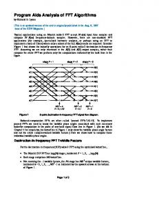
Comparing the complexity of these two approaches suggests that the Mixed-radix algorithm requires only a small amount of additional computations. Moreover, because the Mixed-radix FFT approach is made of smaller-point FFTs, the required FFT can be built using the smaller-point FFTs. Hence Mixed-radix algorithms are proposed to construct the different sizes of FFTs that are required. Figures 8 and 9 show the computational complexity for different GNSS signals using the data specified in Table XII.
Split-radix FFT Approach Mixed-radix FFT Approach
E1B/C-SA
Complexity
In order to compare the complexity of the proposed approaches, we consider the Split-radix algorithms for the power-of-two approaches with the number of real additions and real multiplications according to (Sorensen et al. 1986) (the complex multiplications are treated as 3 real multiplications and 3 real additions). Table XII gives a comparison of the Split-radix approach and the Mixedradix approach. To compute the number of operations for the Mixed-radix algorithms, the factorization according to Table X and the Table IV have been used. As an example, consider the transform length 2048 for which we need 2-point and 1024-point FFT blocks. In the first stage, all the 1024 two-point FFTs are computed. The outputs of these FFTs are then multiplied with the (10241)*(2-1) = 1023 complex coefficients (the other coefficients are unity). In the last stage two 1024-point FFTs are computed to obtain the final output.
Table XII Computational complexity comparison Mixed Radix Multiplications Transform Length 16388 2048 36868 4096 81924 8192 180228 16384 393220 20480 “ 24576 851972 40960 1835012 122880
Additions 61444 135172 294916 638980 1376260 “ 2949124 6291460
L1 C/A
Signal Type
6 Computational the Proposed Approach
L5, E5a/b E1 B/C -DA L2C
L2C
E5
E5
0 0
1
2
3
4
5
6
7
Number of Real Additions x 10 Fig. 8: Number of real additions comparison for FFT of different GNSS signals (Spilt-radix method is used for the standard approach) 6
0.5
1
1.5
Number of Real Multiplications
2 6
x 10
Fig. 9: Number of real multiplications comparison for FFT of different GNSS signals (Spilt-radix method is used for the standard approach)
Shivaramaiah et al.: Application of Mixed-radix FFT Algorithms in Multi-band GNSS Signal Acquisition Engines 182
6.1 Comparing the Complexity of the FFT-based correlator with the Time-based correlator It is interesting to understand the relative complexities of the FFT-based correlation and the time-based correlation method. To obtain the same search time, the time-based correlation process should provide the correlation values simultaneously for all code delays since the FFT-based method does the same. The acquisition performance of such parallel time-domain correlators is experimentally studied in Malik et.al (2009a) and Malik et. al. (2009b). A time-based correlator with 2-bit input and 2-bit local carrier signal should process a 4-bit input for the code correlation and the code correlation is a simple signum function in this case which is then fed to the input port of an accumulator (Shivaramaiah and Dempster 2010). For the GPS L1 C/A signal, computation of each correlation value involves 2046 additions/subtractions. Thus, with an acquisition code phase resolution of half chips, the timebased correlator requires 2046*2046 = 4186116 add/subtract operations. The accumulator width depends on the integration duration, but for one millisecond integration 16-bit accumulator is sufficient (Shivaramaiah and Dempster 2010). With the FFT-based correlation, the number of additions and multiplications to obtain all the correlation values can be computed using Table XII and Fig. 2 and considering that the FFT of the local code is pre-computed and stored in memory. Table XIII shows the FFT-based and timebased correlator complexities for the GPS L1 C/A signal with 2046 cell searches (2048-point FFT). Note that according to Fig. 2, FFT operations in Table XII should be multiplied by two (there is an FFT and an IFFT to execute in real-time) with a complex multiplication inbetween. For the time-based correlator, the number of accumulators has to be doubled because of I and Q local carriers. The code correlation part of the time-based correlator when implemented on a Altera Cyclone family FPGA device consumes 39 LEs for each of the I and Q accumulator (i.e. an accumulator with a feature of add/subtract based on the code bit input). The correlation values for all the delays are obtained by cycling 2046 times through each of the 2046 correlators. It can be observed from Table XIII that even though there are no multipliers required, the time-based correlator consumes huge number of Logic Elements. Having saved 93% of LEs, the multipliers requirement is easily addressed using the multiplier blocks available in the exiting FPGAs. As such, other signals are not considered due to the high resource consumption of the time-based correlators and for the same reason, the time domain correlators are not considered in the results section. 7 Implementation and Resource Utilization on an FPGA As discussed in the previous section, application of the
Table XIII Operations count for the Entire correlator Employing Timebased (2046-tap) and FFT-based (2048-point) methods FFT-based Time-based Additions 125301
Multiplicatio ns 34829
Additions/ Subtractions 8372232
Multiplicatio ns 0
LEs
Multipliers
LEs
Multipliers
11229
39
159588
0
proposed methods reduces the number of computations compared to directly computing the transforms of powerof-two lengths. In addition, instead of having separate FFT blocks for each signal in the receiver, the proposed algorithm uses basic building blocks with which we can construct the required larger FFTs. By ‘constructing’ is meant the combination of smaller blocks using the Mixed-radix approach. The main task of the combination process is to configure the complex multiplication coefficients between the small-point FFT blocks shown in Fig. 4. For hardware resource comparisons we use the number of LE (Logic Elements) and multipliers of the Altera Cyclone family FPGA devices. For the sake of commonality, a data and twiddle precision of 16 is chosen across all the stages of the FFT. Note that in the case of the Mixed-radix approach, by arranging the factors in an increasing order it is possible to use smaller bit widths during the initial stages of the FFT. Also, we make use of the fully- parallel architecture for the smallpoint FFT blocks wherein each 16-bit addition consumes 16 LEs and each multiplication consumes one multiplier block. The number of LEs and multiplier consumption was evaluated for the small-point FFTs and are listed in Table XIV. The reason for selecting a fully parallel architecture is that the blocks can be operated at higher throughput which helps when building larger length FFTs. Table XV gives the FPGA resource utilization for the 1024 point FFT with streaming I/O architecture (Altera 2007). Table XIV FPGA resource utilization for the basic building blocks Transform Length LEs Multipliers 2 9 0 3 192 4 4 256 0 5 544 10 8 832 4 16 2368 20 Table XV FPGA resource utilization for 1024 point FFT Altera MegaCore IP (v7.2) Transform Length LEs Multipliers 1024 5552 18
For the other transform lengths, the pipelined streaming input method is used by combining the appropriate smaller-point FFTs. Hence the resource utilization is influenced by the resource consumed by the combination pattern of the basic building blocks. The requirements of
Shivaramaiah et al.: Application of Mixed-radix FFT Algorithms in Multi-band GNSS Signal Acquisition Engines 183
the memory increases only by an amount of highest value (P - 1) ⋅ (Q - 1) (which is required to hold the complex multiplication coefficients) among all the desired signal combinations. For example, as shown in Fig. 10, a 2048point FFT will require one 2-point block which is serially operated on the input streaming data 1024 times and one 1024-point FFT block which is operated twice, with 1023 complex multiplications in between. The depth [1...1024] and [1, 2] indicate the serial operation of the corresponding FFT blocks. Table XVI lists the resource utilization for larger length FFTs. The * indicates that the Altera core doesn’t exist for these sizes and has been computed by combining the N/2 point FFTs as explained in (Altera 2004).
2 1
1024
1 2-point FFT
Multi pliers
1024point FFT
Complex Coefficients
Fig. 10: Example of Mixed-radix method for a 2048 point FFT
Table XVI FPGA Resource utilization for different transform lengths Proposed Approach (Time-shared architecture) Standard Approach (Altera MegaCore IP ) Transform LEs Multipliers Transform Length LEs Length 2048 7610 36 2048 5556 4096 8011 36 4096 5808 8192 7760 36 8192 6384 16384 8167 36 16384 7920 32768 17337 80 20480 9008 “ “ “ 24576 9584 *65536 34864 160 40960 1464 *131072 69720 352 122880 38768
8 Results and Discussion In this section the results of using the proposed approach for processing selected combinations of the signals are presented. The combinations considered here are as follows: • Combination-I: GPS L1 C/A and Galileo E1B/C-SA • Combination-II: GPS L1 C/A and GPS L2C • Combination-III: GPS L1 C/A, Galileo E1B/C-SA and Galileo E5a/E5b /GPS L5 When using the proposed approach, depending on the acquisition engine design, either the FFT blocks can be time-shared among different signals, or each signal can have its own (independent) FFT processing block. The time-sharing mentioned here is different to the timesharing referred to in the previous section. In the previous section, the computation of a particular length FFT is achieved by time-sharing the smaller FFT blocks. In this section, time-sharing indicates the re-use of FFT blocks among different signals that require FFTs of different lengths. The hardware resource required is the same as that required by the largest FFT among the signals considered. This is referred to as the “signal-timesharing” approach. An example of the signal-time-sharing FFT architecture for Combination-I is shown in Fig. 11. In a GPS L1 C/A + Galileo E1B/C receiver, first the GPS satellites can be searched and then the Galileo satellites or half the number of channels can search for GPS satellites and the other half can search for Galileo satellites (or any other
Multipliers 18 18 22 38 58 62 118 478
scheme). The basic FFT blocks required for this combination are 2, 8 and 1024. For the GPS L1 C/A signal, 1024 serial operations of 2-point FFT block and two operations of 1024-point FFT are performed as explained in the Mixed-radix example described in the previous section. For the Galileo E1 B/C signals, 1024 serial operations of 8-point FFT block and eight operations of 1024-point FFT are performed. Note that the complex multiplication and the coefficients should accommodate the largest FFT under consideration, 8184point in this case. 1024 8 1
2 1
2-point FFT
1024
Multi pliers
1024point FFT
1 8-point FFT
Complex Coefficients
Fig. 11: Example of the signal-time-sharing FFT architecture for Combination-I
Thanks to the Mixed-radix algorithm, the complex multiplication process and coefficients for the 2048-point FFT (the smaller FFT) are subsets of 8184-point FFT (the
Shivaramaiah et al.: Application of Mixed-radix FFT Algorithms in Multi-band GNSS Signal Acquisition Engines 184
200
Number of Multiplier Blocks
larger FFT) and hence no additional memory or multiplies are required for the 2048-point FFT. Another advantage of the Mixed-radix algorithm is that only a quarter of the number of coefficients needs to be stored and hence the memory required is 4196 (2048 real and 2048 imaginary) locations in the current example. Hence in this signal-time-sharing approach the memory required is that of the largest FFT when implemented in the standard power-of-two approach plus a memory of depth equal to a quarter of the length of largest FFT under consideration. In addition there is no increase in the routing resources except for reading the 2048 depth memory into the multipliers.
Standard Proposed - Simultaneous Proposed - Time Shared
180 160 140 120 100 80 60 40 20 0
L1 C/A + E1 B/C -SA
L1 C/A + L2C L1 C/A + E1 B/C + L5/E5a/b
Signal Combination
Fig. 13: Comparison of number of multipliers for different signal In the independent FFT block approach of the Mixedradix method, the hardware and routing resources and the memory of the individual FFTs have to be added and hence the requirements increase compared to the signaltime-sharing approach. However these numbers remain less when compared to the standard power-of-two approach. Note that the time-sharing is not possible with the standard approach as each FFT block has to be independently instantiated. In what follows, we give the percentage improvement in resources of both of these methods over the standard approach. 8.1 Resource combinations
utilization
results
for
different
Figures 12 and 13 give the performance comparison of the standard and proposed approaches for the selected signal combinations respectively. For Combination-I, the saving is about 22% in the number of LEs, and for Combination-III the savings are around 35%. x 10
4
Standard Proposed - Simultaneous Proposed - Time Shared
4 3.5
was used to collect the Intermediate Frequency (IF) signal samples. The IF samples were re-sampled to two samples per chip (so as to obtain 0.5 chip spacing). The samples were then fed to the Altera FPGA for processing. The design with the FFT blocks used Altera DSPBuilder tool in the Matlab Simulink and then programmed to the FPGA. The integration duration of one millisecond for the GPS L1 C/A and 8 ms for the GIOVE-B E1C signals were selected. Figures 14 and 15 show the correlation value (top half) from the standard and the proposed FFT methods respectively. Note that the proposed approach (2*1024 point and 2* 8*1024 point FFTs) closely matched the standard (i.e. 2048 point and 16384 point FFTs) approach. The errors in the correlation values are also plotted in the bottom half of Fig. 14 and 15. Note that the proposed approach has less than two percent error compared to the standard approach. This difference is due to the rounding used during the complex multiplications between the stages in the Mixed–radix method. The loss due to this error is less than 0.1 dB in the correlation value and hence negligible for all practical purposes.
3
Correlation Value
2.5 2 1.5 1 0.5 0
L1 C/A + E1 B/C -SA
500 Proposed Standard
400 300 200 100 0
0
500
1000
1500
2000
2500
L1 C/A + L2C L1 C/A + E1 B/C + L5/E5a/b
Signal Combination Fig. 12: Comparison of number of LEs for different signal combinations
8.2 Proposed FFT test result with the data collected from the real signal: A Case Study The proposed FFT method has been tested with data collected from the real signal for the Combination-I to acquire GPS L1 C/A and GIOVE-B E1C signals in the same platform. The GeNeRx1 receiver from Septentrio
Correlation Error (%)
Number of Logic Elements
4.5
combinations
2 % Error 1 0 -1 -2 0
500
1000
1500
2000
2500
Sample Number
Fig. 14 Acquisition results for the GPS L1 C/A signal; PRN 17; 2048 Point FFT; 1ms integration
Correlation Value
Shivaramaiah et al.: Application of Mixed-radix FFT Algorithms in Multi-band GNSS Signal Acquisition Engines 185
like to thank the reviewers for their constructive feedback on the manuscript.
3000 Proposed Standard 2000
References 1000
0 0.5
1
1.5
2
2.5
3
3.5
4
4.5
Correlation Error (%)
x 10
4
2 % Error 1 0
Altera (2007) FFT MegaCore Function User Guide Version 7.2. Altera Corporation.
-1 -2 0.5
1
1.5
2
2.5
3
Sample Number
3.5
4
4.5 x 10
4
Fig. 15 Acquisition results for the GIOVE-A E1 C signal; 16364 Point FFT realized using standard approach and the proposed Mixed-radix (2*8*1024) approach; 8ms integration
9 Concluding Remarks This paper discussed the requirements for the FFT transform lengths in GNSS receivers which aim to process multiple signals. The proposed method of factorizing large FFT transform lengths into smaller-point FFT blocks eliminates the need for having individual FFTs for different signals. It has been demonstrated that the proposed approach of combining the small-point blocks to build the required large FFTs provides benefits both in terms of reduced computational complexity and increased resource sharing. It is also shown that for the GPS L1 C/A and Galileo E1B/C signal combinations the reduction in complexity is about 22% and the percentage reduction is also high for other signal combinations. From these results it can be concluded that the proposed approach has two advantages: •
•
Altera (2004) FFT 32K Point Design Example v1.0.0, Altera Corporation. URL http://www.altera.com/support/exam ples/verilog/ver-fft-32k.html.
Code acquisition with longer codes can be practically achieved via the FFT-based method (through the use of small-point FFT blocks), without having to implement a FFT of large transform length. Multi-band GNSS receivers can make use of smallpoint FFTs from a common set of building blocks, hence reducing the design complexity and increasing the re-usability.
The proposed method is a potential candidate for acquisition engines in future multi-band GNSS receivers. Acknowledgments The authors would like to acknowledge that this research work has been carried out under the Australian Research Council (ARC) project DP0556848. The authors would
Burrus CS, Selesnick IW (1995) On Programs for Prime Length FFTs and Circular Convolution. In: Proc. IEEE ICASSP 1995, vol. 2, ISSN 1520-6149, pp. 1137– 1140, doi:10.1109/ICASSP.1995.480436. De Wilde W, Sleewaegen JM, Simsky A, Van Hees J, Vandewiele C, Peeters E, Grauwen J, Boon F (2006) Fast signal acquisition technology for new GPS/Galileo receivers. In: Proc. IEEE PLANS 2006, pp. 1074–1079. Dempster AG (2006) Correlators for L2C: Some Considerations. Inside GNSS :pp. 32–37. Dempster AG (2007) Satellite Navigation: New Signals, New Challenges. In: Proc. IEEE ISCAS 2007, pp. 1725– 1728, doi:10.1109/ISCAS.2007.377927. Dempster AG, Hewitson S (2007) The ’System of Systems’ Receiver: an Australian Opportunity? In: Proc. IGNSS, Sydney, Australia. Diggelen, Frank-van (2009) A-GPS Assisted GPS, GNSS and SBAS, Artech House Djebouri D, Djebbari A, Djebbouri M (2006) Robust GPS Satellite Signal Acquisition Using Lifting Wavelet Transform. Radio Engineering vol. 15(1). Gunawardena, S (2000), Feasibility Study for the Implementation of Global Positioning System Block Processing Techniques in Field Programmable Gate Arrays, Master’s Thesis, Ohio University Holmes JK (2007) Spread Spectrum Systems for GNSS and Wireless Communications. Artech House. IRN-705003 (2005) Navstar GPS Space Segment/User Segment L5 Interfaces. IS-GPS-200 (2006) Navstar Segment/Navigation User Interfaces.
GPS
Space
Shivaramaiah et al.: Application of Mixed-radix FFT Algorithms in Multi-band GNSS Signal Acquisition Engines 186
Kaplan E, Hegarty C (eds.) (2006) Understanding GPS: Principles and Applications. 2nd edn., Artech House.
Signal Processing, IEEE Transactions on, vol. 34(1):pp. 152–156, ISSN 0096-3518.
Malik, S. A., Shivaramaiah, N. C. & Dempster, A. G. (2009a), ’Search engine trade-offs in FPGA-based GNSS receiver designs’ European Navigation Conference ENC-GNSS’, 3-6 May, Naples, Italy.
Starzyk J, Zhu Z (2001) Averaging Correlation for C/A Code Acquisition and Tracking in Frequency Domain. Circuits and Systems, 2001 MWSCAS 2001 Proceedings of the 44th IEEE 2001 Midwest Symposium on vol. 2:pp. 905–908 vol.2, doi:10.1109/MWSCAS.2001.986334.
Malik, S. A., Shivaramaiah, N. C. & Dempster, A. G. (2009b), ’FPGA-based GNSS Search Engine using Parallel Techniques in the Time-Domain’ IGNSS Symp’, 1-3 Dec, Gold Coast, Australia Mumford PJ, Parkinson K, Dempster AG (2006) The Namuru Open GNSS Research Receiver. In: Proc. ION GNSS 2006, Fort Worth, USA, pp. 2847–2855. OS-SIS-ICD (2008) Galileo Open Service Signal In Space Interface Control Document. Proakis JG, Manolakis DG (2006) Digital Signal Processing, Principles, Algorithms, and Applications. 4th edn., Prentice Hall. Qaisar SU, Shivaramaiah NC, Dempster AG (2008) Exploiting the Spectrum Envelope for GPS L2C Signal Acquisition. In: Proc. ENC GNSS 2008, Toulouse, France. Rizos C (2007) The Future of Global Satellite Navigation Systems. In: 3rd Workshop for Space, Aeronautical & Navigational Electronics, IEICE Tech. Rept.107(2), Perth, Australia, pp. 25–30. Sajabi C, Chen CIH, Lin DM, Tsui JBY (2006) FPGA Frequency Domain Based GPS Coarse Acquisition Processor Using FFT. In: Proc. IEEE IMTC 2006, ISSN 1091-5281, pp. 2353–2358, doi:10.1109/IMTC.2006.328619. Shivaramaiah, N. C. and Dempster A.G. (2010), ’On the baseband hardware complexity of Modernized GNSS receivers’, IEEE International Symposium of Circuits and Systems ISCAS-2010, 30 May- 2 June, Paris, France (accepted for publication) Shivaramaiah, N. C. & Dempster, A. G. (2008), ’An Analysis of Galileo E5 Signal Acquisition Strategies’ European Navigation Conference, ENC-GNSS’, 23-25 April, Toulouse, France Smith WW (1995) Handbook of Real-Time Fast Fourier Transforms : Algorithms to Product Testing. John Wiley & Sons. Sorensen H, Heideman M, Burrus C (1986) On Computing the Split-radix FFT. Acoustics, Speech and
Van Nee DJR, Coenen AJRM (1991) New Fast GPS Code-acquisition Technique Using FFT. Electronics Letters vol. 27(2):pp. 158–160, ISSN 0013-5194, doi:10.1049/el:19910102. Yang C (2001) FFT Acquisition of Periodic, Aperiodic, Punctured and Overlaid Code Sequences in GPS. In: Proceedings of the ION GPS Conference, Salt Lake City, Utah.
BIOGRAPHY Nagaraj C Shivaramaiah is currently a doctoral student within the GNSS receiver design group in the School of Surveying and Spatial Information Systems at the University of New South Wales, Australia. He has a Masters degree in Electronics Design and Technology from the Indian Institute of Science, Bangalore, India. He has been involved in GNSS related research since the late 1990s. Prior to joining UNSW, he worked at Freescale Semiconductors, Bangalore and Accord Software and Systems, Bangalore, where he focused on baseband signal processing for GNSS receivers, GPS correlator ASIC design and A-GNSS. His research interests include GNSS receiver design, baseband signal processing, embedded and reconfigurable hardware design and software defined radios.