Home
Search
Collections
Journals
About
Contact us
My IOPscience
Application of PI Current Controller in Single Phase Inverter System Connected to Non Linear Load
This content has been downloaded from IOPscience. Please scroll down to see the full text. 2017 IOP Conf. Ser.: Mater. Sci. Eng. 226 012135 (http://iopscience.iop.org/1757-899X/226/1/012135) View the table of contents for this issue, or go to the journal homepage for more Download details: IP Address: 191.96.251.154 This content was downloaded on 14/08/2017 at 13:35 Please note that terms and conditions apply.
International Research and Innovation Summit (IRIS2017) IOP Publishing IOP Conf. Series: Materials Science and Engineering 226 (2017) 012135 doi:10.1088/1757-899X/226/1/012135 1234567890
Application of PI Current Controller in Single Phase Inverter System Connected to Non Linear Load Tracy Chai Anak Ajot, Suriana Salimin*, Roziah Aziz Faculty of Electrical and Electronic Engineering, Universiti Tun Hussein Onn Malaysia, Malaysia. Corresponding Email:
[email protected] Abstract. This study is concerned with the problem of network power quality when inverter systems are connected to a nonlinear load. Nonlinear loads are well known as one of the biggest source of harmonics in the power system. Besides that, inverter systems also have their nonlinearity characteristic because of the electronic components. As the inverter system is connected to nonlinear load, it resulting in harmonic distortion-related problem and draw non-sinusoidal currents in the system, thus reducing the power quality in the system. The application of Proportional Integral controller in this system is the main interest of this study. This current controller capable of reducing total harmonic distortion and improve the state of current waveform. This paper focuses on application of simple manual trial and error tuning technique to produce the optimum value for the gains. The result of study verifies the trial and error manual tuning of PI current controller in compensating harmonic distortions. Simulation and modelling of the system are successfully developed using Matlab/Simulink.
1. Introduction The development of power electronic components is rapid in the recent times. One of power electronic components that is very popular is inverter. Today, inverter system becomes one of power electronic system that is widely applied in many sectors such as in industry system, power transmission, residential and portable consumer devices. Inverter or which is also well known as DC-AC converter is a device that is used to convert dc input voltage into ac output voltage of variable magnitude and frequency [1]-[3]. The system is a source converter to a linear or nonlinear load. However, a massive usage of inverter system in nonlinear load condition has become a big concern to utilities and industrial world. This concern is because of the big impact of the nonlinearity behaviours of the inverter and nonlinear load into power quality in power system [4]. The nonlinearity behaviours of inverter and nonlinear load cause the voltage and current of the system being harmonics which then lead to the destructive of the overall power system [5]. Hence, the implementation of IEEE 519 standard [5]-[7] and IEC standards [8] which set the compatibility of total harmonic distortion (THD) in a power system is very important. Recently, various elimination or compensation techniques for harmonics distortion in inverter system have been introduced to satisfy the requirement of the standard. One of the techniques is by using a proportional integral current controller. This technique is chosen as the main focused for this study. From previous researcher reported that PI current controller has a good control performance, easy to implement and has high reliability which is explaining the high application of the controller in industry field [9]-[10].
Content from this work may be used under the terms of the Creative Commons Attribution 3.0 licence. Any further distribution of this work must maintain attribution to the author(s) and the title of the work, journal citation and DOI. Published under licence by IOP Publishing Ltd 1
International Research and Innovation Summit (IRIS2017) IOP Publishing IOP Conf. Series: Materials Science and Engineering 226 (2017) 012135 doi:10.1088/1757-899X/226/1/012135 1234567890
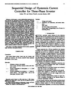
It can give a major effect on the quality of the current supplied by the inverter [9], [11]-[12] and enhance the performance of the system. Therefore, approving the ability of the conventional PI current controller to compensate the total harmonic distortion (THD) in a single-phase inverter system is set as the aim of this study. The design of a single-phase inverter system with RLC filter as well as the design of full bridge rectifier which is set up as the nonlinear load and also the design of PI current controller are presented in this report. At the end of the study, the total harmonic distortion (THD) and the generated output waveform in two different conditions whereby PI current controller is disconnected and connected are being analysed. The simulation is performed by using Matlab software. Figure 1 below demonstrates the basic diagram of Inverter system connected to nonlinear load with PI current controller.
Fig. 1 Block diagram of Inverter System with PI control technique 2. System Design 2.1 Inverter System Design
Fig. 2: Single Phase Inverter System Model Figure 2 shows the single phase inverter circuit that is used in this power system. The proposed single phase inverter consists of full bridge DC-AC module. It contains a full bridge inverter that consists of four MOSFETs with internal diodes, PWM generator and DC Bus voltage. The DC is used to store power rectified by the converter before being supplied to inverter [14]. The inverter is supplied with 380 VDC and use a 20 kHz switching frequency. MOSFETs are used as a switch because it is suitable to work under low
2
International Research and Innovation Summit (IRIS2017) IOP Publishing IOP Conf. Series: Materials Science and Engineering 226 (2017) 012135 doi:10.1088/1757-899X/226/1/012135 1234567890
voltage application. Its voltage rating is less than 500 V. The gates of the MOSFETs are triggered using the PWM pulses. The pulses are obtained from the PWM generator. 2.2 PWM Generator The carrier frequency of the PWM generator is set to 20 kHz with a modulation index of 0.8. Modulation index of 0.8 is chose to prevent from over modulation as well as under modulation. The typical switching frequency is range between 1 kHz up to 20 kHz. 20 kHz is used because of it has good balancing in conduction and switching losses in typical MOSFET switched applications [13][15]. Besides that, higher frequency can reduce audible noise [13]-[14] and yield better current waveform. 2.3 RLC Low Pass Filter The RLC Low pass filter is placed at the output of inverter module to obtain the sinusoidal current and voltage. The design of low pass filter is depending on several points and equations. Firstly, a second order RLC low pass filter is used at the output stage. Usually, passive low pass filter in inverter system is designed around a cut-off frequency in the range of 500 Hz-1500 Hz [13]. The cut-off frequency set up for the filter is 1 kHz. The inductance value is approximately to 0.003H. Applying the cutoff frequency formula, the cutoff frequency is initially set to 1 kHz and the value of inductor is 3mH. Overall parameter of the filter are 12Ω for the resistance, 0.003H for the inductor, and 6.8µF for the capacitor. Then, the final cut-off frequency is 1.1 kHz. 2.4 Single phase Full Bridge Rectifier A full bridge rectifier is connected to the output as the nonlinear load. Its function is to convert the AC back to DC source. For this simulation, universal bridge is used to form a single full bridge rectifier. It has value of 0.8V for the threshold. For the normal diodes, the range is 0.6 to 0.8V [16]. The model of rectifier system is shown as Figure 3. The capacitor-inductor filter is connected to the rectifier output. The purpose of capacitor-inductor filter is to improve the filtering action of rectified voltage and current. The function of the capacitor is to smooth out the distortion in voltage while the inductor is used to smooth out the distortion in current [17]. Transformer is used to provide isolation between inverter system and the load. Besides, the transformer steps down the voltage into lower value to be injected to the rectifier.
Fig. 3: Single Phase Full Bridge Rectifier Model 2.5 PI Controller Model The transfer function for conventional PI controller is expressed as; 𝐺(𝑠) = 𝐾𝑃 +
3
𝐾𝐼 𝑠
(1)
International Research and Innovation Summit (IRIS2017) IOP Publishing IOP Conf. Series: Materials Science and Engineering 226 (2017) 012135 doi:10.1088/1757-899X/226/1/012135 1234567890
𝐾𝑃 is the proportional gain term and 𝐾𝐼 is the integral gain term. Figure 4 shows the conventional PI current controller Simulink model used in this system. The measured inverter output current is signed as I_INVERTER. The output of the controller, which is signed as OutController is then compared with a 20 kHz triangular wave signal in PWM generator. For obtaining a suitable value of 𝐾𝑃 and 𝐾𝐼 , trial and error technique is used in this simulation. Initially, the gains are set to 0, then the values are slowly increased to specific value till up to the point whereby the acceptable and the lowest total harmonic distortion (THD) is achieved. The chosen parameter of 𝐾𝑃 is 0.03 and 𝐾𝐼 is 0.001 for the best result.
Fig. 4: Conventional PI Current Controller 3. Simulation of System Design The four main models; single inverter system, low pass filter, nonlinear load and PI controller are modelled in Simulink and simulated using simulation time of 0.1s with time sample of 8x10⁻⁷s. Table I shows the list of parameters applied in the system. The harmonic distortion in the current output is measured and obtained from the Fast Fourier transform (FFT) analysis. The sample taken is 5 cycles starting from of 0 sec to 0.1 sec. The Total Harmonic Distortion (THD) and signal of the current is analysed. Table I. List of parameters of model Parameter DC Voltage Source, VDC Frequency,f Switching Frequency, fsw Sample Time,TS Simulation Time,T Low Pass Filter
Capacitor-Inductor Filter
Proportional Gain,KP Integral Gain,KI Forward Voltage,Vf Transformer
Value 380V 50Hz 20kHz 0.8μs 0.1s RF =12Ω, LF = 3mh CF = 6.8μF CF = 2.5mF LF =12.5mH RLOAD =10Ω 0.03 0.001 0.8V 220/120V
3.1 Simulation of Single Phase Inverter System without nonlinear Load
4
International Research and Innovation Summit (IRIS2017) IOP Publishing IOP Conf. Series: Materials Science and Engineering 226 (2017) 012135 doi:10.1088/1757-899X/226/1/012135 1234567890
From the FFT result analysis, the inverter output current shows a THD of 1.12%. The result shows the present of harmonic in the inverter current output before nonlinear load connected. Thus, the nonlinearity nature of inverter is verified. Figure 5 demonstrates the inverter output voltage waveform which is in square form, before low pass filter is connected while figure 6 demonstrates the inverter output current. Although the waveform shows less distortion, the peak exceeds 20A, which is more than desired result.
Fig. 5: Inverter output voltage
Fig. 6: Inverter output current 3.2 Simulation of Single Phase Inverter System nonlinear Load without PI current Controller For this case, a full bridge rectifier is added into the system as the nonlinear load. Single-phase rectifier with capacitor filter is a typical nonlinear load [17]. When rectifier is added to the system, the total harmonic distortion (THD) should be increased. Figure 7 shows the inverter output current signal after the rectifier is added in the system. From the signal, it can be seen that the output current signal is distorted. FFT analysis is then performed. It run for 0.1 sec of simulating time, with 5 cycles and 0.8 μsec of sample time.
Fig. 7: Inverter output current with nonlinear load before connecting PI The THD achieved is 5.52% with high harmonics appear at odd harmonic between the 3rd and 19th order. The THD increases about 4.4% from previous simulation. These harmonics are the focus in this simulation that need to be eliminated and reduced using PI controller. 3.3 Simulation of Single Phase Inverter System Nonlinear Load Connected With PI Current Controller The reference current is set to 20 A because the system is assumed to work at 3 kW. Figure 8 shows the inverter output current after PI controller is applied. It can be seen that the distortion in the waveform is smoother and the shape of waveform is improved.
5
International Research and Innovation Summit (IRIS2017) IOP Publishing IOP Conf. Series: Materials Science and Engineering 226 (2017) 012135 doi:10.1088/1757-899X/226/1/012135 1234567890
Fig. 8: Inverter output current of PI controller The total harmonic distortion is measured again using FFT analysis with the same starting time and cycles as earlier. The THD achieved is 0.70%. There is a huge decreased in the THD. The THD is dropped about 4.82%. 3.4 Comparison of Total Harmonic Distortion (THD) With and Without PI Current Controller Figure 9 shows the harmonics spectrum of inverter output current in both states; with PI controller and without PI controller. From the figure, it clearly states that the odd harmonics magnitude between 3rd and the 19th harmonic orders have been reduced.
Fig. 9: The harmonic spectrum of inverter output current without and with PI current controller Table II shows the THD produced at each number of harmonic starting from 3 rd to 19th when the system disconnected and connected to PI current controller. From the table, it clearly shows that the THD is higher at 3rd harmonic. This is because the 3rd harmonic is near to the fundamental frequency which is 50Hz, which is very hard to reduce. However, the THD between 3rd and the 19th have been reduced. The higher order harmonics beyond the 19th are less severe because of the 1 kHz cut-off frequency of low pass filter.
6
International Research and Innovation Summit (IRIS2017) IOP Publishing IOP Conf. Series: Materials Science and Engineering 226 (2017) 012135 doi:10.1088/1757-899X/226/1/012135 1234567890
Table II. Total harmonic distortion (THD) in every harmonic numbers with and without pi current controller Frequency Harmonic Mag (% of (Hz) Number fundamental) WITHOUT WITH PI PI 150 3 4.95 0.06 250 5 1.81 0.04 350 7 0.95 0.02 450 9 0.75 0.01 550 11 0.38 0.01 650 13 0.32 0.01 750 15 0.38 0 850 17 0.17 0.01 950 19 0.21 0.01 4. Discussion The performance of a PI current controller used in single inverter system connected to nonlinear load is demonstrated. From the result obtained, it can be found that the performance of the inverter system connected in nonlinear load condition is better when PI current controller is applied. Before the conventional PI current controller applied to the system, the harmonic data shows a THD of 5.52% with high magnitudes on the 3th to the 19th harmonic orders. The level is higher than the compatibility of the THD set by IEEE 512-1992 which is 5% for the overall THD. In order to improve the spectrum and reduce the THD in current output, a PI current controller is applied. The gain of 𝐾𝑃 and 𝐾𝐼 are tuned using trial and error. Firstly, KP and are set to zero. Then, the 𝐾𝑃 and 𝐾𝐼 are slowly increased with random value. The process is continued until the desired THD is achieved. Thus, the final result is 0.03 for 𝐾𝑃 and 0.001 for 𝐾𝐼 . The THD is 0.70% which is about 4.82% reduction from the system when PI current controller has not applied. The THD is acceptable under the IEEE 512-1992 standard. Previous research has reported that PI control is able to reduce harmonic in inverter system but has inability to track a sinusoidal reference with zero steady-state error and poor disturbance rejection capability. From the waveform also clearly shows that the output current signal is still following the reference current signal however there are some distortions in the waveform which means that the output still suffers of steady-state error. Nevertheless, the distortion becomes smoother after PI current controller applied. The aim of this study which is to demonstrate the capability of PI current controller to reduce harmonic in current output of inverter system nonlinear load connected is verified. 5. Conclusion This paper proposed a conventional PI current controller modelling in a single phase inverter system connected to nonlinear load to compensate harmonic distortion in current output for power quality improvement in the system. Complete review of PI current control technique to eliminate or compensate harmonics for inverters is done. The state of current output when the PI current controller is absent and present also has been compared and verified using Matlab Simulink software. Based on this finding, the proportional plus integrated controller has reduced the DC component and steady state error in the current output. A proper injection of gain of 𝐾𝑃 and 𝐾𝐼 into the controller is vital to achieve a better harmonic performance. There are various tuning algorithms have been applied to the PI controller. In this study, the technique applied is by trial and error technique. The result of study verifies the trial and error manual tuning of PI current controller in compensating harmonic distortions of inverter system with non-linear load.
7
International Research and Innovation Summit (IRIS2017) IOP Publishing IOP Conf. Series: Materials Science and Engineering 226 (2017) 012135 doi:10.1088/1757-899X/226/1/012135 1234567890
Acknowledgement The author would like to thank Universiti Tun Hussein Onn (UTHM) for the opportunity and sponsoring for this conference. References [1] V.R. Moorthi. 2015 Power Electronics (Devices, Circuits, and Industrial Applications). Oxford: Oxford University Press. [2] Rashid. M. H. 2011 Power Electronics Handbook: Devices, Circuits and Applications. 3rd Edition. UK: Butterworth-Heinemann. [3] Chaudhary K. R and M J. Mod. 2015. Switching Control of Inverter Using SPWM Technique. International Journal of Innovative Research in Technology (IJIRT). LDCE, Ahmedabad: Vol 1, Issue 12, ISSN: 2349-6002. [4] Suresh N, Babu SRR. 2015. Review on Harmonics and its Eliminating strategies in Power System. Indian Journal of Science and Technology. Jul, 8(13): 1-9 [5] Y. Ping, Z. Qunru, X. Zhirong, Y. Haozhe and Z. Yuanhui, 2014. Research on nonlinear phenomena of single-phase H-bridge inverter. IEEE PES Asia-Pacific Power and Energy Engineering Conference (APPEEC), Hong Kong, 2014, pp.1-6. [6] IEEE Recommended Practices and Requirements for Harmonic Control in Electrical Power Systems. IEEE Std 519-1992 [7] S. Salimin, M. Armstrong, and B. Zahawi, 2013. Randomized integral gain of PI current controller for a single PV inverter system. Engineering, vol. 5, no. 1, pp. 221. [8] Kiank H. and Fruth W. 2011 Planning Guide for Power Distribution Plants: Design, Implementation and Operation of Industrial Networks. Germany, Publicis Erlangen [9] Vinay Sharma, Dharm Prakash Diwakar, Nishant Tripathi. 2014. Comparative Study of PI and Proportional Resonant Control for Single-Phase Grid Connected Inverter System. International Journal of Emerging Technologies and Engineering (IJETE). [10] Q. Jin and Q. Liu. 2014. Multi-loop PI/PID controllers design for disturbance rejection based on nonparametric effective model and non-convex optimization. IET Control Theory & Applications, vol. 8, no. 15, pp. 1499-1512. [11] Zammit, D., Staines, C. S. & Apap, M. 2014. Comparison between PI and PR current controllers in grid connected PV inverters. WASET, International Journal of Electrical, Electronic Science and Engineering, 8(2). [12] Hannoun, H., Hilairet, M., & Marchand, C. 2007). Gain-scheduling PI current controller for a switched reluctance motor. In Industrial Electronics, 2007. ISIE 2007. IEEE International Symposium on (pp. 1177-1182). [13] Salimin S. 2014. Low Order Harmonics Mitigation In Grid Connected, Parallel PV Inverters. School of Electrical, Electronics and Computer Engineering Newcastle University: PhD Thesis [14] Kudamm Corporation. Myths and facts about VFD carrier frequency. New Delhi, Delhi. [15] T. Huanqi, L. Suyi. 2011. Design and Implementation of Digital Control of Photovoltaic Power Inverter. Procedia Environmental Sciences. 11. pp. 155-162. [15] B. P. Singh, Rekha Singh. 2006. Electronic Devices and Integrated Circuits. India. Dorling Kindersley. [16] Hong Yi, Jiyang Dai and Jiaju Wu. 2008. Research on modeling and control of the single-phase inverter system with a nonlinear load. 7th World Congress on Intelligent Control and Automation, Chongqing. pp. 6095-6100. [17] Pyakuryal.S, Matin. M. 2013. Filter Design for AC to DC Converter. International Refereed Journal of Engineering and Science. 2(6). pp. 42-49. .
8