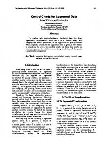
Hindawi Publishing Corporation Journal of Control Science and Engineering Volume 2016, Article ID 1467823, 7 pages http://dx.doi.org/10.1155/2016/1467823
Research Article Application of Residual-Based EWMA Control Charts for Detecting Faults in Variable-Air-Volume Air Handling Unit System Haitao Wang College of Civil Engineering and Architecture, Henan University of Technology, Zhengzhou 450001, China Correspondence should be addressed to Haitao Wang;
[email protected] Received 10 December 2015; Revised 7 March 2016; Accepted 14 March 2016 Academic Editor: Xiao He Copyright © 2016 Haitao Wang. This is an open access article distributed under the Creative Commons Attribution License, which permits unrestricted use, distribution, and reproduction in any medium, provided the original work is properly cited. An online robust fault detection method is presented in this paper for VAV air handling unit and its implementation. Residual-based EWMA control chart is used to monitor the control processes of air handling unit and detect faults of air handling unit. In order to provide a level of robustness with respect to modeling errors, control limits are determined by incorporating time series model uncertainty in EWMA control chart. The fault detection method proposed was tested and validated using real time data collected from real VAV air-conditioning systems involving multiple artificial faults. The results of validation show residual-based EWMA control chart with designing control limits can improve the accuracy of fault detection through eliminating the negative effects of dynamic characteristics, serial correlation, normal transient changes of system, and time series modeling errors. The robust fault detection method proposed can provide an effective tool for detecting the faults of air handling units.
1. Introduction With progress in distributed control and model predictive control systems, the benefits to various industrial segments such as chemical, petrochemical, cement, steel, power, and desalination industries have been enormous [1]. However, fault detection and diagnosis (FDD) still is a very important supervisory control task in managing process plants. Fault detection and diagnosis has been included in control systems through building automation system (BAS) or embedded into heating, ventilating, air-conditioning, and refrigeration systems (HVAC&R) equipment [2]. Successful fault detection and diagnosis (FDD) can save 15∼30% of variable-air-volume (VAV) air-conditioning system energy consumption [3, 4]. Air handling unit (AHU) which is one of the most important and extensively operated equipment pieces in large commercial buildings tends to have more faults for higher automatic control requirements, being customized, and lacks quality system integration [5]. The broad scope of fault detection and diagnosis in AHU fields has been increased continuously because of various computer-aided techniques with low-cost
installation. Extensive research has been conducted during the past decades to identify different fault diagnosis methods that are suitable for air handling units. Three approaches including analytical-based method [6–8], knowledge-based method [9–11], and data-driven method [12–14] are used in these researches. Proper design and normal operation of air handling units are essential for reliable operation and energy efficiency of VAV air-conditioning systems. However, in the VAV air handling unit system, temperature, flow rate, and pressure are essential process variables to normal operation of air handling unit system. Supply air temperature control process, supply air pressure control process, and fresh air flow rate control process are three main control processes of air handling units. Most faults of air handling unit are sensitive to the cumulative small changes as well as some abrupt changes in supply air temperature values, supply air pressure values, and fresh air flow rate values. However, supply air temperature, supply air pressure, and fresh air flow rate at a short sampling interval (5 minutes) can be proved to be highly correlated by calculating the autocorrelation function,
2
Journal of Control Science and Engineering Return air temperature sensor T Damper
Return air fan
Exhaust air
Return air Recirculation air PID PID Damper Supply air
Fresh air
Damper
Filter F
T
Fresh air temperature sensor
Mixture air temperature sensor
Heating and cooling coil
Supply air fan
T Supply air temperature sensor
Figure 1: Schematic of VAV air handling unit and measurement instrumentation.
respectively. Therefore, residual-based control chart which is the most widely investigated method for autocorrelated processes can be used to detect faults and abnormalities of air handling units. Literature review shows that there is still a lack of reliable, affordable, and scalable FDD methods for air handling unit [5]. The causes of this problem include insufficient sensor information, modeling limitations, and the complexity of concurrent faults. An appropriate fault detection approach for AHU systems should have more desirable characteristics. One of the main requirements of fault detection method is that very few false alarms are generated. Because VAV airconditioning systems operate under very diverse weather, varied internal load conditions, and changing operation points, VAV air-conditioning system is nonstationary and has more normal transient changes. Variables associated with air handling unit vary drastically with the changes of operation conditions. Therefore, fault detection method should be robust enough to cope with the nonstationary characteristics and normal transient changes of air handling unit systems. In this paper, a robust fault detection method is presented for faults of air handling units by using the residual-based EWMA control chart method. In order to provide a level of robustness with respect to modeling errors, control limits are determined by incorporating time series model uncertainty information into EWMA control chart. Residual-based EWMA control chart with designing control limits can improve the fault detection accuracy through eliminating the negative effects of dynamic characteristics of system, serial correlation in monitoring data, normal transient changes of system, and modeling errors of time series model.
2. Air Handling Unit System Description Air handling unit is one of the most important equipment pieces in VAV air-conditioning system. Air handling units are controlled together with distribution terminals to provide heating, cooling, and fresh air for each conditioned space in buildings. Air handling unit system is where energy is exchanged between the liquid system and the air system. Air handling unit system is where outdoor air is introduced into a building. Air handling unit consists usually of supply air fan, return air fan, a mixing box, fresh air damper, exhausted air damper, recirculation air damper, heating and cooling coils, PID controller, and sensors. As shown in Figure 1, in the air handling unit, the mixing box mixes the fresh air and the recirculation air. The heating and cooling coils heat up or cool down the mixed air to maintain the required supply air temperature and humidity. The supply fan equipped with variable frequency drive can adjust the air flow according to the load conditions. The performance of control system is important for normal operation and energy efficiency of air handling units. Supply air temperature control system, supply air pressure control system, and fresh air flow rate control system are three main control systems of air handling unit. Supply air temperature is controlled at its setpoint by cooling coil, chilled water valve, PID controller, and supply air temperature sensor. Supply air pressure is maintained at its setpoint by a fan controlled by an inverter, a supply air pressure sensor, and a pressure transducer. Enough fresh air flow rate is provided by a fresh damper, an air flow rate sensor, fresh air temperature sensor, and PID controller.
Journal of Control Science and Engineering
3
Faults of air handling unit mean that some components do not operate properly according to the design intent. Faults of air handling unit can be separated into four types: design problem, equipment failure, actuator failure, and sensor and feedback controller failure. Typical design problem includes too high chilled water temperature setpoint, too low chilled water temperature setpoint, too high fresh air fraction setpoint, too low fresh air fraction setpoint, and undersized cooling coil. Equipment failure can be separated into system disturbance which normally interacts with a modeling approach and structural failure that involves malfunctions in the equipment of air handling unit. Equipment failure includes faulty supply air fan, belt slippage, and fouling cooling coil. Actuator (dampers and valves) failure will directly interact with an AHU plant for modulating the system inputs, which could cause the deviation of the plant outputs beyond acceptable limits. Actuator (dampers and valves) failure includes fresh air damper failure, return air damper failure, and cooling coil valve failure. Sensor fault will misrepresent the true condition of the systems. Sensor and feedback controller failure will cause the performance of controllers to degrade gradually. Typical sensor and feedback controller failure includes supply air temperature sensor failure, mixed air temperature sensor failure, return air temperature sensor failure, fresh air temperature sensor failure, supply air pressure sensor failure, fresh air humidity sensor failure, fresh air flow rate sensor failure, return air flow rate sensor failure, and PID controller failure.
3. Robust Fault Detection Method for Air Handling Units 3.1. Negative Effects of Model Uncertainty on Residual-Based EWMA Control Chart. Residual-based EWMA control chart is derived from the control chart method, which is a general method in statistical control engineering to monitor controlled variables. Residual-based EWMA control chart is one of the most widely investigated methods which have been proposed to deal with correlated data recently. In the residualbased EWMA control chart method, ARMA(𝑝, 𝑞) model with estimated parameters is utilized to generate residuals which are no longer statistically independent. Then, standard EWMA control chart is used to monitor the residuals between the observation and its prediction of ARMA(𝑝, 𝑞) model [15]. In practical engineering, modeling errors of ARMA(𝑝, 𝑞) model are usually unavoidable because of being estimated from the limited amounts of historical data. When modeling errors are unavoidable, the residuals generated via the ARMA(𝑝, 𝑞) models are no longer statistically independent [16], as shown below:
𝜔𝑖 =
̂ (𝐵) ̂ (𝐵) 𝜃 (𝐵) 𝜙 𝜙 𝑥𝑖 = 𝑎𝑖 , 𝜃̂ (𝐵) 𝜃̂ (𝐵) 𝜙 (𝐵)
𝜃 (𝐵) = 1 − 𝜃1 𝐵 − 𝜃2 𝐵2 − ⋅ ⋅ ⋅ − 𝜃𝑞 𝐵𝑞 , 𝜙 (𝐵) = 1 − 𝜙1 𝐵 − 𝜙2 𝐵2 − ⋅ ⋅ ⋅ − 𝜙𝑝 𝐵𝑝 ,
(1)
where 𝑥𝑖 is the process data at sampling time 𝑖; 𝜃̂ is an estimate of the moving average polynomials constructed from the ̂ is an estimate of the autoregressive estimated parameters; 𝜙 polynomials constructed from the estimated parameters; 𝑎𝑖 is an identically independently distributed zero-mean random sequence that follows a normal distribution with variance 𝜎02 ; 𝐵 is the backward shift operator; 𝜔𝑖 is the residual at sampling time i. Suppose a residual-based EWMA control chart is utilized to monitor ARMA processes. The residual-based EWMA control chart is defined as 𝑧𝑖 = (1 − 𝜆) 𝑧𝑖−1 + 𝜆𝜔𝑖 ,
(2)
where 𝑧𝑖 is the value of EWMA statistic at sampling time 𝑖; 𝑧𝑖−1 is the value of EWMA statistic at sampling time 𝑖 − 1; 𝜔𝑖 is the residual at sampling time 𝑖; EWMA parameter 𝜆 is a suitable constant, 0 < 𝜆 ≤ 1, 𝜆 being determined by using the method proposed in Montgomery [17]. The upper control limit (UCL) and lower control limit (LCL) of EWMA control chart are calculated as follows: ̂ 0 + 𝐿̂ 𝜎𝑜 , UCL = 𝜇 ̂ 0 − 𝐿̂ 𝜎𝑜 , LCL = 𝜇
(3)
where UCL is the upper control limit of EWMA control chart; ̂ 0 is LCL is the lower control limit of EWMA control chart; 𝜇 an estimate of in-control process mean of the residuals; the constant 𝐿 is chosen to provide a desired in-control average run length, and tables developed by Lucas and Saccucci [18] ̂ 0 is are used in this study to determine suitable 𝐿 values; 𝜎 an estimate of in-control process standard deviation of the residuals. In presence of estimation errors, the actual standard deviation of the residuals 𝜎𝑧 may differ from the in-control process standard deviation of the residuals 𝜎0 [14]. Autocorrelation in modeling errors will have large impact on the incontrol average run length of residual-based EWMA control charts [19, 20]. 𝜎𝑧 will be larger than 𝜎0 , and the resulting incontrol average run length will be shorter than the desired one [19]. 3.2. Designing of Control Limits of Residual-Based EWMA Control Chart. In order to provide a level of robustness with respect to modeling errors, model uncertainty information is incorporated into the EWMA control charts. Equation (4) is used in this paper to determine chart limits for the residualbased EWMA control chart: ̂ 0 + 𝐿𝜎𝑧 , UCL = 𝜇 ̂ 0 − 𝐿𝜎𝑧 , LCL = 𝜇
(4)
where UCL is the upper control limit of EWMA control chart; ̂ 0 is LCL is the lower control limit of EWMA control chart; 𝜇 an estimate of in-control process mean of the residuals; the constant 𝐿 is chosen to provide a desired in-control average run length, and tables developed by Lucas and Saccucci [18] are used in this study to determine suitable 𝐿 values; 𝜎𝑧 is the actual standard deviation of the residuals.
4
Journal of Control Science and Engineering
The unconditional variance 𝑧𝑖 is determined by the following methods [21]: 2 𝜎𝑧2 = 𝐸 [𝑧𝑖2 ] = 𝐸 [𝐸 [𝑧𝑖2 | 𝛾̂]] = 𝐸 [𝜎𝑧|̂ 𝛾] ,
𝜐𝑖 =
1 𝑎, 𝜃 (𝐵) 𝑖
(5) (6)
∞
2 2 2 2 𝜎𝑧2 ≅ 𝐸 [𝜎𝑧,̂ 𝛾 ] = (1 − 𝜐) 𝜎𝑎 ∑ 𝐸 [𝑔𝑗 ] , 𝑗=0
∞
∑ 𝐸 [𝑔𝑗2 ] =
𝑗=0
∑𝜙 1 + 𝜐𝜙 1 {1 + [ ] 2 2 1−𝜐 1 − 𝜙 1 − 𝜐𝜙
2 ∑𝜙𝜃 ∑𝜃 1 − 𝜐2 𝜙𝜃 1 + 𝜐𝜃 ]} , [ ]− [ + 2 1 − 𝜃 1 − 𝜐𝜃 1 − 𝜙𝜃 (1 − 𝜐𝜙) (1 − 𝜐𝜃) 𝜎𝑧2 ≅ (
(7)
∞ 1−𝜐 2 ) 𝜎𝑎 + (1 − 𝜐)2 𝜎𝑎2 ∑ 𝑔𝑗𝑇 ∑ 𝑔𝑗 , 1+𝜐 𝛾 𝑗=0
(8)
(9)
where 𝜃 is coefficient vector of moving average model; ∑𝜃 is variable moving average parameter estimate; 𝜙 is coefficient vector of autoregressive model; ∑𝜙 is variable autoregressive parameter estimate; ∑𝜙𝜃 is covariance between autoregressive parameter estimates and moving average parameter estimates; 𝛾 is ARMA parameter vector; 𝛾̂ is the estimated parameter vector of ARMA model; ∑𝛾 is covariance matrix 2 of ARMA parameter estimates; 𝜎𝑧|̂ 𝛾 is conditional EWMA variance for 𝛾̂; 𝑔𝑗 is impulse response function of EWMA model [21]; 𝐸 is the expectation operator; 𝜐 = 1 − 𝜆; 𝜆 is EWMA parameter. The EWMA variance for ARMA(1, 1) processes becomes 𝜎𝑧2 ≅ 𝜎02 (
1 + 𝜐𝜙 1−𝜐 1 + 𝜐𝜃 + ) [1 + ], 1+𝜐 𝑛 (1 − 𝜐𝜙) 𝑛 (1 − 𝜐𝜃)
(10)
where 𝑛 is the number of observations used to estimate ARMA model. For AR(1) and MA(1) processes, the results are similar. Substituting ∑𝛾 = (1−𝜙12 )/𝑛 into (10) with ∑𝜃 = ∑𝜙𝜃 = 𝜃 = 0, the EWMA variance for AR(1) processes becomes 𝜎𝑧2 ≅ 𝜎02 (
1 + 𝜐𝜙 1−𝜐 ]. ) [1 + 1+𝜐 𝑛 (1 − 𝜐𝜙)
(11)
Substituting Σ𝛾 = (1 − 𝜃12 )/𝑛 into (10) with ∑𝜙 = ∑𝜙𝜃 = 𝜙 = 0, the EWMA variance for MA(1) processes becomes 𝜎𝑧2 ≅ 𝜎02 (
1−𝜐 1 + 𝜐𝜃 ]. ) [1 + 1+𝜐 𝑛 (1 − 𝜐𝜃)
(12)
In this study, ARMA model parameters are unknown, so 𝜎𝑧 cannot be directly used in (4) to calculate the control limits. The recommended procedure is to substitute the parameter estimates for their true values in (9), (10), (11), and (12). The extent to which the control limits are widened depends on the level of model uncertainty. The EWMA control chart with designing control limits can cope with modeling errors well.
3.3. Errors of Air Handling Unit Control Processes. Supply air temperature control process, supply air pressure control process, and fresh air flow rate control process are three main control processes in air handling units. Supply air temperature error, supply air pressure error, and fresh air flow rate error are identified in this paper as three generic errors. The supply air temperature error is defined as the error between measured supply air temperature and its setpoint. The supply air pressure error is defined as the error between measured supply air pressure and its setpoint. The fresh air flow rate error is defined as the error between measured fresh air flow rate and its setpoint. Most faults of air handling units will result in a deviation of one or more of the three errors from its value during normal operation, which can be detected by the residual-based EWMA control chart. The supply air pressure error is effective for detecting slipping supply fan drive belt, tuning problem with the air flow control PID loop, sequencing logic error, and supply air pressure sensor fault. The supply air temperature error is effective for detecting cooling coil valve fault, too high or low chilled water supply temperature, fouled cooling coil, chilled water circulating pump failure, undersized cooling coil, too high or low fresh air fraction, and supply air temperature sensor fault. The fresh air flow rate error is effective for detecting fresh air damper failure, wrong control logic, and too high or low fresh air fraction. 3.4. Overviews of Fault Detection Method of Air Handling Unit. When residual-based EWMA control chart is applied to monitoring the control processes of air handling unit, the process parameters representing some quality characteristic of the control processes are unknown. Modeling errors are usually unavoidable because of being estimated from the limited amounts of historical data. Therefore, residual-based EWMA control chart with designing control limits is used in this paper to detect faults of air handling units. Flow chart of fault detection method of air handling units using residualbased EWMA control chart is shown in Figure 2. The fault detection method includes the following three steps: (1) Incontrol process parameters and ARMA model parameters are offline estimated from historical, fault-free operating data. (2) Upper and lower control limits are determined by using the method presented in Section 3.2. (3) Residual-based EWMA control chart with designing control limits is online used to detect faults or abnormalities of air handling units. When the VAV air-conditioning systems operate, 𝑧 values of supply air temperature error, supply air pressure error, and fresh air flow rate error are calculated, respectively. 𝑧 values will be reset to zero when the VAV air-conditioning systems are shut down. If LCL < 𝑧𝑖 < UCL, it means the air handling unit operates normally. If 𝑧𝑖 > UCL or 𝑧𝑖 < LCL, it implies a fault or abnormity in the corresponding air handling unit. The advantage of the fault detection method presented is that residual-based EWMA control chart with designing control limits can improve the fault detection accuracy through eliminating the negative effects of dynamic characteristics of system, serial correlation in monitoring data, normal transient changes of system, and modeling errors of time
Journal of Control Science and Engineering The historical, fault-free operating data
In-control mean and ARMA model of supply air temperature error
In-control mean and ARMA model of supply air pressure error
In-control mean and ARMA model of fresh air flow rate error
Calculating lower control limit and upper control limit of EWMA control chart
5 Read current data from SQL server
Calculating supply air temperature error, supply air pressure error, and fresh air flow rate error
Generating the residuals using ARMA model of supply air temperature error, supply air pressure error, and fresh air flow rate error Applying EWMA control charts to the residual of supply air temperature error, supply air pressure error, and fresh air flow rate error
zi > UCL
Yes
No
zi < LCL
Fault report Yes
No
Figure 2: Flow chart of fault detection for VAV air handling units.
series model. The fault detection method proposed can be conveniently implemented on real buildings as it relies only upon the rated parameters of air handling units as well as sensor and control signals that are commonly available in energy management and control systems (EMCS).
4. Validation and Discussions 4.1. Building and Faults Introduction. The fault detection method proposed was validated on VAV air-conditioning systems of an office building. Every floor of the office building is served by a single duct VAV air-conditioning system. The building employs a fully automated energy management and control system, which performs the environmental control of the indoor spaces. Operating data of VAV air-conditioning systems is gathered and stored in a database (SQL server) at 5-minute interval. The huge amount of data available in the SQL server provides rich information for monitoring, optimization, and diagnosis of VAV air-conditioning systems. A computer program based on the fault detection method proposed was developed and connected to the SQL server. The computer program can access operating data from the SQL server and detect faults of VAV air handling units. In order to obtain the quality characteristic of control processes and determine parameters of time series models, half-year operation data of VAV air-conditioning systems were logged at 5-minute interval. To test the fault detection method proposed, data sets for several types of artificial faults were collected from the real office building. Artificial faults are intentional man-made faults by introducing a faulty component or setting. Introducing artificial faults is often the only solution for testing a fault detection and diagnosis method
in a real environment. Descriptions of the fault introductions and fault detection results are provided below. 4.2. Too Low Supply Air Pressure. Too low supply air pressure was introduced to the AHU system at the 27th floor through sticking the cooling coil with plastic tapes from sample 1. Plastic tapes increase the local resistance of cooling coil, which results in that measured supply air pressure is substantially less than the supply air pressure setpoint. EWMA corresponding to too low supply air pressure is shown in Figure 3. EWMA values exceed the designed lower control limit at sample 10. It indicates that a fault of air handling unit is detected by the fault detection method successfully. The potential causes of this fault include slipping faulty fan, supply fan drive belt, wrong control logic, and supply air pressure sensor fault. On-site personnel investigation is needed to find the fault source. 4.3. Supply Air Temperature Sensor Fault. Supply air temperature sensor fault was introduced to the AHU system at the 27th floor through replacing the supply air temperature sensor with a faulty one from sample 37 in the SQL server (database). The supply air temperature setpoint is 15∘ C. The measured supply air temperature can match its setpoint well before introducing the supply air temperature sensor fault. The measured supply air temperature is around 12.909∘ C after introducing the supply air temperature sensor fault. EWMA corresponding to supply air temperature sensor fault is shown in Figure 4. EWMA values do not exceed the designed upper and lower control limits before introducing the supply air temperature sensor fault. EWMA values exceed the designed upper control limit at sample 46. It means that a fault of air handling unit is found by the fault detection method
6
Journal of Control Science and Engineering 2
4
0 −2
EWMA
EWMA
0
−4
−4 −6 −8
−8
−10
−12
5
10
15
20
25
30
−12
0
10
Sample (n) Lower control limit Designed upper control limit
Designed lower control limit Value of EWMA Upper control limit
Figure 3: EWMA corresponding to too low supply air pressure.
20
30 Sample (n)
Designed lower control limit Value of EWMA Upper control limit
40
50
60
Lower control limit Designed upper control limit
Figure 5: EWMA corresponding to cooling coil valve fault.
12
EWMA
8
4
0
−4
0
10
20
30 Sample (n)
Designed lower control limit Value of EWMA Upper control limit
40
50
60
Lower control limit Designed upper control limit
Figure 4: EWMA corresponding to supply air temperature sensor fault.
successfully. The potential causes of this fault include faulty cooling coil valve, too high chilled water supply temperature, fouled cooling coil, chilled water circulating pump failure, undersized cooling coil, too high fresh air fraction, and supply air temperature sensor fault. On-site personnel investigation is needed to determine the fault cause. 4.4. Stuck Cooling Coil Valve. An artificial fault was introduced to cooling coil valve of the AHU system at the 27th floor through manually constraining valve from sample 37. Normally, the supply air temperature control system will turn
up cooling coil valve when the supply air temperature is higher than its setpoint. The measured supply air temperature can match its setpoint well before introducing the artificial cooling coil valve fault. The measured supply air temperature is much lower than its setpoint after introducing the artificial cooling coil valve fault. However, chilled water valve of cooling coil is always higher than 48.707%. EWMA corresponding to the artificial cooling coil valve fault is shown in Figure 5. EWMA values do not exceed the designed upper and lower control limits before introducing the artificial cooling coil valve fault. EWMA values exceed the designed upper control limit at sample 39. It flags that a fault of air handling unit is found by the fault detection approach presented successfully. The potential causes of this fault include stuck cooling coil valve, too low chilled water supply temperature, too low fresh air fraction, and supply air temperature sensor fault. On-site personnel investigation is needed to find the fault source.
5. Conclusions The increasing performance demands on control system and the growing complexity of VAV air-conditioning system have created a need for fault detection tool. A fault detection method has been presented in this paper for VAV air handling units by using residual-based EWMA control charts with designing control limits. The fault detection method proposed is validated by using the operation data from real VAV air-conditioning systems involving multiple artificial faults. Results of validation show that residual-based EWMA chart with designing control limits can monitor the operating status of air handling unit and detect faults of air handling unit correctly. Residual-based EWMA control chart with designing control limits can improve the fault detection accuracy through eliminating the negative effects of dynamic characteristics of system, serial correlation in monitoring
Journal of Control Science and Engineering data, normal transient changes of system, and modeling errors of time series model. The fault detection method relies only upon the sensor and control signals that are commonly available in energy management and control systems. The fault detection method presented can provide an online and effective tool for detecting faults of air handling units.
Competing Interests The author declares that there are no competing interests regarding the publication of this paper.
Acknowledgments The research work presented in this paper is financially supported by the National Natural Science Foundation of China (no. 51406048), Educational Commission of Henan Province of China (no. 15A560006), and Fundamental Research Funds for the Henan Provincial Colleges and Universities in Henan University of Technology (2015RCJH17).
References [1] O. Nasri, I. Gueddi, P. Dague, and K. Benothman, “Spacecraft actuator diagnosis with principal component analysis: application to the rendez-vous phase of the mars sample return mission,” Journal of Control Science and Engineering, vol. 2015, Article ID 204918, 11 pages, 2015. [2] P. Li, P. F. Odgaard, J. Stoustrup, A. Larsen, and K. Mørk, “Model-based fault detection and isolation of a liquid-cooled frequency converter on a wind turbine,” Journal of Control Science and Engineering, vol. 2012, Article ID 684610, 21 pages, 2012. [3] M. A. Piette, S. K. Kinney, and P. Haves, “Analysis of an information monitoring and diagnostic system to improve building operations,” Energy and Buildings, vol. 33, no. 8, pp. 783–791, 2001. [4] D. Westphalen, K. W. Roth, and J. Brodrick, “System and component diagnostics,” ASHRAE Journal, vol. 45, no. 4, pp. 58– 59, 2003. [5] Y. B. Yu, D. C. Woradechjumroen, and D. H. Yu, “A review of fault detection and diagnosis methodologies on air-handling units,” Energy and Buildings, vol. 82, pp. 550–562, 2014. [6] S.-H. Cho, H.-C. Yang, M. Zaheer-Uddin, and B.-C. Ahn, “Transient pattern analysis for fault detection and diagnosis of HVAC systems,” Energy Conversion and Management, vol. 46, no. 18-19, pp. 3103–3116, 2005. [7] S. R. Shaw, L. K. Norford, D. Luo, and S. B. Leeb, “Detection and diagnosis of HVAC faults via electrical load monitoring,” HVAC and R Research, vol. 8, no. 1, pp. 13–40, 2002. [8] S. Wu and J.-Q. Sun, “A physics-based linear parametric model of room temperature in office buildings,” Building and Environment, vol. 50, pp. 1–9, 2012. [9] J. Schein, S. T. Bushby, N. S. Castro, and J. M. House, “A rulebased fault detection method for air handling units,” Energy and Buildings, vol. 38, no. 12, pp. 1485–1492, 2006. [10] H. Yang, S. Cho, C.-S. Tae, and M. Zaheeruddin, “Sequential rule based algorithms for temperature sensor fault detection in air handling units,” Energy Conversion and Management, vol. 49, no. 8, pp. 2291–2306, 2008.
7 [11] Y. Zhao, J. Wen, and S. W. Wang, “Diagnostic Bayesian networks for diagnosing air handling units faults—part II: faults in coils and sensors,” Applied Thermal Engineering, vol. 90, no. 5, pp. 145–157, 2015. [12] B. Fan, Z. M. Du, X. Q. Jin, X. B. Yang, and Y. B. Guo, “A hybrid FDD strategy for local system of AHU based on artificial neural network and wavelet analysis,” Building and Environment, vol. 45, no. 12, pp. 2698–2708, 2010. [13] X.-B. Yang, X.-Q. Jin, Z.-M. Du, and Y.-H. Zhu, “A novel modelbased fault detection method for temperature sensor using fractal correlation dimension,” Building and Environment, vol. 46, no. 4, pp. 970–979, 2011. [14] T. J. Harris and W. H. Ross, “Statistical process control procedures for correlated observations,” Canadian Journal of Chemical Engineering, vol. 69, no. 1, pp. 48–57, 1991. [15] D. W. Apley, “Time series control charts in the presence of model uncertainty,” Journal of Manufacturing Science and Engineering, Transactions of the ASME, vol. 124, no. 4, pp. 891– 898, 2002. [16] D. W. Apley and H. C. Lee, “Design of exponentially weighted moving average control charts for autocorrelated processes with model uncertainty,” Technometrics, vol. 45, no. 3, pp. 187–198, 2003. [17] D. C. Montgomery, Introduction to Statistical Quality Control, John Wiley & Sons, New York, NY, USA, 3rd edition, 1996. [18] J. M. Lucas and M. S. Saccucci, “Exponentially weighted moving average control schemes: properties and enhancements,” Technometrics, vol. 32, no. 1, pp. 1–29, 1990. [19] B. M. Adams and I.-T. Tseng, “Robustness of forecast-based monitoring schemes,” Journal of Quality Technology, vol. 30, no. 4, pp. 328–339, 1998. [20] C.-W. Lu and M. R. Reynolds Jr., “EWMA control charts for monitoring the mean of autocorrelated processes,” Journal of Quality Technology, vol. 31, no. 2, pp. 166–188, 1999. [21] G. E. Box, G. M. Jenkins, and G. Reinsel, Time Series Analysis, Forecasting, and Control, Prentice Hall, Englewood Cliffs, NJ, USA, 3rd edition, 1994.
International Journal of
Rotating Machinery
Engineering Journal of
Hindawi Publishing Corporation http://www.hindawi.com
Volume 2014
The Scientific World Journal Hindawi Publishing Corporation http://www.hindawi.com
Volume 2014
International Journal of
Distributed Sensor Networks
Journal of
Sensors Hindawi Publishing Corporation http://www.hindawi.com
Volume 2014
Hindawi Publishing Corporation http://www.hindawi.com
Volume 2014
Hindawi Publishing Corporation http://www.hindawi.com
Volume 2014
Journal of
Control Science and Engineering
Advances in
Civil Engineering Hindawi Publishing Corporation http://www.hindawi.com
Hindawi Publishing Corporation http://www.hindawi.com
Volume 2014
Volume 2014
Submit your manuscripts at http://www.hindawi.com Journal of
Journal of
Electrical and Computer Engineering
Robotics Hindawi Publishing Corporation http://www.hindawi.com
Hindawi Publishing Corporation http://www.hindawi.com
Volume 2014
Volume 2014
VLSI Design Advances in OptoElectronics
International Journal of
Navigation and Observation Hindawi Publishing Corporation http://www.hindawi.com
Volume 2014
Hindawi Publishing Corporation http://www.hindawi.com
Hindawi Publishing Corporation http://www.hindawi.com
Chemical Engineering Hindawi Publishing Corporation http://www.hindawi.com
Volume 2014
Volume 2014
Active and Passive Electronic Components
Antennas and Propagation Hindawi Publishing Corporation http://www.hindawi.com
Aerospace Engineering
Hindawi Publishing Corporation http://www.hindawi.com
Volume 2014
Hindawi Publishing Corporation http://www.hindawi.com
Volume 2014
Volume 2014
International Journal of
International Journal of
International Journal of
Modelling & Simulation in Engineering
Volume 2014
Hindawi Publishing Corporation http://www.hindawi.com
Volume 2014
Shock and Vibration Hindawi Publishing Corporation http://www.hindawi.com
Volume 2014
Advances in
Acoustics and Vibration Hindawi Publishing Corporation http://www.hindawi.com
Volume 2014