Application of UML for Hardware Design Based on Design Process Model Robertas Damasevicius, Vytautas Stuikys Kaunas University of Technology, Software Engineering Department, Studentu 50, 3031-Kaunas, Lithuania, Tel: (370-37) 300-399; Fax: (370-37) 300-352 E-mail:
[email protected],
[email protected]
Abstract - We address a problem of reusing and customizing soft IP components by introducing a concept of design process a series of common, well-defined and well-proven domainspecific actions and methods performed to achieve a certain design aim. We especially examine system-level design processes that are aimed at designing a hardware system by integrating soft IPs at a high level of abstraction. We combine this concept with object-oriented hardware design using UML and metaprogramming paradigm for describing generation of domain code.
I. INTRODUCTION Consumer market drives the microelectronics industry to provide new semiconductor products that are faster, cheaper and more reliable. New emerging ideas envision human environment saturated with hi-tech gadgets that provide every kind of telecommunication, information processing, multimedia, and entertainment capabilities the user wishes to have. Hardware (HW) designers are coming under particular strain to design the 21st century technology using design methods that are usually several years behind the design methods enjoyed by software (SW) designers. A common way to increase quality and productivity in HW design is to reuse IP (Intellectual Property) components (IPs). IPs are original components that were created by a human designer, are portable, and can be used by other designers. Soft IPs are IPs that are described in a high-level HW description language (HDL) such as VHDL, Verilog or SystemC. For several decades, the main objective of a HW designer was to design a HW component that is reliable and efficient (in terms of area, speed, or power). Main efforts of researchers were directed at development and perfecting of HDLs, modeling and testing methodologies, optimization and synthesis tools. This HW design direction can be called content-based design, because it focuses on creating and qualifying IP content, rather than considering how it can be used later. The result is a plethora of soft IPs that were designed for different applications using different requirements, design methods and design tools. The main objective of a modern HW designer is not as much as creating new soft IPs, but rather searching, evaluating, reusing and integrating third-party soft IPs into a designed system. This HW design direction is sometimes called integration-based design. It requires new habits from designers: sharing rather than protecting IP, designing for reuse rather than for use, designing to solve a general problem rather than designing for a specific application, customizing rather than developing from scratch, and fully documenting a designed soft IP (HW system). We address a problem of reusing and customizing soft IPs using a concept of design process - a series of commonly used domainspecific actions, tasks or methods performed to achieve a certain design aim. We combine this concept with the object-oriented (OO) design (OOD) techniques. OOD is based on the concept of using high-level models organized around real world concepts. This approach has gained great popularity among the SW engineering community, and has actually become the de-facto standard for SW
design. In this paper, we will demonstrate that this methodology can also be applied to integration-based HW design successfully. UML [1] has gained acceptance as a high-level system specification and modeling language that combines the OO concepts for structural design of a system using class diagrams alongside with the behavioral models (state, sequence and activity diagrams). These models combine features of Petri nets, state machines, and flow charts, capable of representing concurrent, conditional, and iterative flow of data and control. UML allows describing the structural or behavioral relationship between components with design patterns [2]. These are used to abstract and encapsulate common design solutions as well as to describe contexts to which they can be applied in a language-independent way. When used systematically, design patterns allow to increase design quality and productivity. Our aim is (1) to describe and specify some HW design processes using UML, and (2) to adapt the OOD methodology for designing HW systems in VHDL. The novelty of this paper is as follows. (1) Design Process Model, a framework for integrating OOD concepts, domain-specific concepts (HW design processes), metaprogramming paradigm and generative reuse (SW generators). (2) Taxonomy of HW design processes. (3) Mapping (metamodel) between UML class diagrams and structural VHDL abstractions. The structure of the paper is as follows. Section II reviews the related work. Section III analyzes the concept of HW design processes. Section IV presents taxonomy of HW design processes. Section V presents a Design Process Model, describes its layers, considers mapping OOD (UML) concepts to VHDL and discusses implementation of HW design processes using metaprogramming. Section VI presents a case study. Section VII evaluates and discusses the results. Finally, Section VIII presents the conclusions.
II. RELATED WORK Application of the OOD techniques for HW design is a complex issue. We categorize the related research into several streams: (1) development of high-level abstractions (models, frameworks) for applying OOD techniques for HW design, (2) application of UML as a high-level specification language for HW design, (3) application of design patterns described using UML class diagrams for HW design, and (4) generation of HDL code from UML diagrams.
A. Development of models for OO HW design Nebel and Schumacher [3] analyze the OO modeling techniques as a means to increase productivity in HW design. The largest gain is expected when the subjects of OOD are not the physically existing objects (e.g., gates), but abstract concepts for solving the design problems. Ecker [4] proposes an approach to adding OOD aspects to HW entities based on structural inheritance that is similar to our approach. It facilitates the extension of entity-architecture pairs for additional generics, ports, declarations, and concurrent statements. Böttger et al. [5] present an OO model for IP reuse in HW design. The model has three layers. (1) Specification layer captures func-
tional and structural requirements of a system. (2) Function layer contains functional properties of the domain. (3) Architectural layer represents possible implementations of system's functions. Model generators are used to map an OO model of a system to not necessarily OO target languages like VHDL. Kuhn et al. [6] describe two views on objects in HW design. The structural view interprets objects as components and methods as ports/connections. The behavioral view treats objects as connections between components that are represented by the methods. Radetzki [7] presents an extensive survey of OO languages and approaches in HW design domain.
B. Application of UML for HW design Hallal et al. [8] use UML for high-level modeling and design of IP-based systems alongside with block diagrams. This allows reducing complexity by using composition relations and indicating common functionality by using generalization relations. Martin [9] discusses the capabilities and lacks of UML for embedded system design, and formulates the requirements for future extensions to UML to support platform-based design. De Jong [10] combines UML with SDL for design of real-time and embedded systems. UML is used to present an "external" view to a system. SDL is used to formally specify the implementation of a system. Zhu et al. [11] propose a System-on-Chip (SoC) design methodology based on UML and C++/SystemC. The authors report the reduction of design time by about one-third compared to conventional design methods.
C. Application of design patterns for HW design Doucet and Gupta [12] present a system-level HW design methodology that uses UML and design patterns to capture the models of computation (abstractions of design functionality). Yoshida [13] analyzes the applicability of SW design patterns to SoC design, and concludes that some SW design patterns can be applied for HW design, however, further research is needed to discover new HW design patterns. Selic [14] discusses the ability of UML to describe architectures at all levels of granularity, and identifies the fundamental structural relationships (micro-patterns) that are similar to our concept of design operations. Micro-patterns can be combined in different ways to produce a vast spectrum of different architectural patterns to suit different application domains and requirements.
D. Generation of HDL code from UML diagrams McUmber and Cheng [15] present a framework for generating VHDL specifications from a subset of UML, and a set of rules to map UML class and state diagrams to VHDL. The authors concentrate on UML behavioral models described using state diagrams, and use a mapping for class diagrams that differs from our approach. Björklund and Lilius [16] generate VHDL code from UML behavioral models (state and activity diagrams) using SMDL as an intermediary language. Sinha et al. [17] present an approach for modeling embedded systems using extended UML as well as generating SystemC code from UML class and object diagrams.
III. HARDWARE DESIGN PROCESSES A. System-level design As the complexity of HW design is constantly increasing, designers are seeking to adopt new design methods that could increase productivity and shorten time to market. This can be achieved by moving HW design to higher levels of abstraction above the traditional gate-level design. One particular buzzword currently used in a HW design domain is system-level design. There are several definitions of what system-level HW design is: (1) System-level design is design of a SoC that has HW and embedded SW parts [18]. For example, design of a microprocessor that has a running program in its memory. (2) System-level design is design of a system (SoC or pure HW) by reusing IPs as basic building blocks [19]. For example, design of a microprocessor using pre-designed ALU, RAM and bus controller. Obviously, the second definition is much broader and mainly focuses on IP reuse issues, while the first one mostly emphasizes HW/SW co-design and co-simulation. We use a more general IPbased definition of system-level design in this paper, since systemlevel design of SoC is usually IP-based, too.
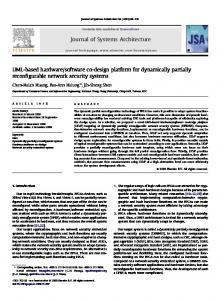
B. Design processes: definition, properties, categories To analyze HW design at a high level of abstraction, we introduce a concept of design process: "A design process is a series of commonly used well-defined domain-specific actions, tasks or methods performed in order to achieve a well-formulated design aim". We formulate the properties of design processes below: (1) Processes are domain-specific (e.g., SW patterns usually can not be used for HW design right away). (2) Processes are commonly used by designers in the domain. (3) Processes are transformative in nature, i.e. they are about transforming their input (data, programs, syntax trees) into output. (4) Processes are executable, i.e., they not only describe what is done, but also imply how it can be done using some well-defined method or approach (this requires good documentation). (5) Processes are design context-specific, i.e. they reside within a certain design framework (e.g., platform-based design [20]). Depending upon the size and scale of designed HW components (systems), we categorize design processes as follows (see Fig. 1): (1) Gate-level design processes (operations) are lower-level content-based design processes aimed at IP design from scratch. For example, manual programming of behavioral models in VHDL. (2) System-level design processes (patterns) are higher-level integration-based design processes that are aimed at designing a HW system from the pre-designed soft IPs at a high level of abstraction. For example, soft IP customization, adaptation, and integration. Successful system-level HW design requires thorough analysis and documentation of HW design processes. In Section IV, we present taxonomy of HW design processes and their specification using UML class diagrams. Gate-Level Design
E. Summary The usage of object-orientation in HW domain is widening at all levels of abstraction from high-level specification using UML to low-level implementation using OO HW architectures (platforms). The researchers (1) emphasize the importance of structuring, encapsulation and reuse of HW designs at the highest levels of abstraction, (2) suggest using the OOD techniques (including OO HDLs, design patterns and UML diagrams) for HW and embedded systems modeling and design, (3) propose different mapping schemes between the OOD concepts (expressed using UML) and HW domain (described using a HDL), and (4) suggest using the generative techniques to automatically generate HW models from UML diagrams.
System-Level Design
is
is
Hardware Design depends
depends
depends
Hardware Design Process is Design Operation
is *
1 has
Design Pattern
Fig. 1. Hardware design processes: UML-based view.
C. Relation to SW design patterns A similar concept to HW design process in SW engineering is design pattern. To explain the difference, we present several definitions of what the patterns are: (1) “Descriptions of communicating objects and classes that are customized to solve a general design problem in a particular context” [2]. This definition defines design patterns in terms of OOD methodology, however, not all design patterns are object-oriented. (2) “The abstraction from a concrete form which keeps recurring in specific non-arbitrary contexts” [21]. This definition emphasizes the abstract nature and broad applicability of design patterns. (3) “Both a description of a thing which is alive, and a description of the process which will generate that thing” [22]. This definition describes the so-called generative patterns that not only describe system architectures, but also tell us how to design them. (4) "A proven, successful approach and/or series of actions for developing software" [23]. Such are process patterns that encapsulate knowledge about SW development processes and workflows. In our approach, a HW design process is, in fact, more than a simple design pattern. It is rather a domain-specific generative process pattern that includes both documentation (well-proven models, natural language descriptions, UML diagrams), which describes a design solution, as well as domain code components and tools (parsers, generators, etc.), which implement the solution.
IV. TAXONOMY OF HARDWARE DESIGN PROCESSES
A
A
B
B
A
B
(a) A
(b) A
B
A
B
B
C
(d)
(c)
(e)
C
(f)
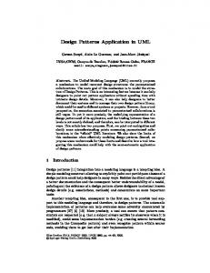
Fig. 2. Hardware design operations: (a) refinement, (b) widening, (c) narrowing, (d) containment, (e) logical composition, (f) physical composition.
4) Containment SW analog: composition. Intent: to insert a lower-level component into a higher-level component. Description: higher-level component A contains a lower-level component, which is represented by its interface B (see Fig. 2, d). Applicability: design of a hierarchical system using soft IPs. 5) Logical composition SW analog: multiple inheritance. Intent: to compose a component interface using several base interfaces. Description: interface C is composed from interfaces A and B (see Fig. 2, e). Relationship: uses widening. Applicability: design of a hierarchical system using soft IPs.
A. Principles of description In this Section, we present an OO view to HW design processes. To describe HW design processes, we have adopted a description scheme used for SW design patterns [2]. It contains six essential parts: (1) Unique name identifying the design process. (2) Analog in SW domain. HW design processes can be traced back to their equivalent design patterns in SW domain, however, a design process implies more than a design pattern, therefore, we use our own names for design processes. (3) Intent that concisely formulates a design problem. (4) Description of a solution in natural language with UML class diagrams representing the involved classes and their roles. (5) Relationship (if any) with other design processes. (6) Applicability: sub-domain and typical examples of application. First, we describe basic HW design processes (operations), and then we describe more complex design processes (patterns) that combine several design operations for system-level HW design.
B. HW design operations 1) Refinement SW analog: realization. Intent: to provide an implementation for a component interface. Description: component B provides an implementation for interface A (see Fig. 2, a). Applicability: design of a HW component from scratch. 2) Widening SW analog: inheritance. Intent: to extend an interface of a component with new ports. Description: interface B inherits all ports from interface A and additionally declares new ports (see Fig. 2, b). Applicability: adaptation of soft IPs to a wider context of application (e.g., adding a clock signal for component synchronization, or a reset signal for low power). 3) Narrowing SW analog: generalization. Intent: to reduce an interface of a component by removing some of its ports. Description: interface B is a reduced version of interface A with some of its ports removed (see Fig. 2, c). Applicability: adaptation of soft IPs to a narrower context of application (e.g., removing some unnecessary ports).
6) Physical composition SW analog: multiple composition. Intent: to compose a component using several base components. Description: component A is composed from lower-level components, which are represented by their interfaces B and C (see Fig. 2, f). Relationship: uses containment. Applicability: design of a hierarchical system using soft IPs.
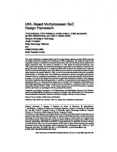
C. HW design patterns 1) Wrapping SW analog: Decorator design pattern. Intent: to wrap a component with additional functionality. Description: interface B inherits its ports from interface A and declares the additional ones. Component B_Model implements interface B and wraps component A_Model that implements interface A with additional functionality (see Fig. 3, a). Relationship: uses widening, containment and refinement. Applicability: adaptation of soft IPs to a context of application (e.g., communication interface design, fault-tolerant design). 2) Specialization SW analog: Adapter design pattern. Intent: specialize a component with respect to some of its ports. Description: interface B inherits a narrowed interface from interface A. Component B_Model implements interface B, contains component A_Model and specializes some of its inputs (Fig. 3, b). Relationship: uses narrowing, containment and refinement. Applicability: adaptation or optimization of soft IPs by reducing their context of application. 3) Composition SW analog: Decorator, Composite design patterns. Intent: to compose a component from several base components, as well as to inherit their interfaces. Description: interface C inherits ports from interfaces A and B. Component C_Model implements interface C and is composed from components A_Model and B_Model (see Fig. 3, c). Relationship: uses physical and logical composition, refinement. Applicability: design of a hierarchical system using soft IPs.
ModelElement A
A_Model
A
Classifier B
A_Model
B
(a)
B_Model
B_Model
A
(b)
Interface (entity) * 1 1 * Inheritance
1
(a) *
Composition (port map)
N: integer
B
Class (architecture) 1 1 *
1 Realization (of)
Relationship
A N
A_Model
C
B_Model
(d)
(c)
C_Model
C
ModelElement
B
Classifier 1
Fig. 3. Hardware design patterns: (a) wrapping, (b) specialization, (c) composition, (d) recursive composition.
4) Recursive composition SW analog: Composite design pattern. Intent: to implement a component that has a recursive structure. Description: interface A has a generic parameter N that characterizes the recursive structure of its implementation. Component B is an implementation of interface A that is composed of N instances of component C. Component C is an implementation of interface A when N = 1 (see Fig. 3, d). Relationship: uses containment and refinement. Applicability: design of HW components with generic data path width, e.g., adders, registers, multiplexer arrays.
V. DESIGN PROCESS MODEL AND ITS IMPLEMENTATION A. Mapping UML to VHDL By describing HW design processes using UML class diagrams, we aim at specifying a HW system at a high level of abstraction and, eventually, automatically generating HDL code. To achieve this aim, we must describe (1) a mapping between the OOD concepts expressed using a subset of UML and the HDL abstractions (we are specifically interested in VHDL), and (2) the translation rules between the UML-based specification of a HW model and the HDLbased implementation of a HW component using the metaprogramming techniques (see sub-section V.B). A mapping is usually described semi-formally using an UML metamodel [24], i.e. the model that describes the syntax of UML diagrams using a small subset of UML. A metamodel consists of a class diagram, where classes describe the syntactic components of the used UML diagram. An instance of the UML metamodel is any UML model described using a subset of UML defined in the metamodel. Below, as an example we present a metamodel of a mapping between UML class diagrams and a structural subset of VHDL (see Fig. 4). VHDL abstractions are shown in braces. Elements of UML class diagrams are classifiers, relationships and features. Classifiers are interfaces and classes that describe basic design blocks. Relationships (Fig. 4, a) describe different types of connections and associations between classifiers. Features (Fig. 4, b) describe parameters, attributes and methods of classifiers. We map an abstract class (interface) to a VHDL entity. A class that realizes an interface is mapped to a VHDL architecture. Class parameters are mapped to a VHDL generic statement, attributes - to the VHDL ports (public) and signals (private), and methods – to the VHDL processes (procedures). The inheritance relationship means that a VHDL entity inherits the I/O ports from a base entity (there is no corresponding abstraction in VHDL). The composition relationship describes composition of a system from the components and is mapped to a VHDL port map statement. The realization relationship is mapped to a VHDL entity-architecture pair.
Interface (entity) 1
1
* Public attribute (port)
(b)
* Method (process)
* Parameter (generic)
1
Class (architecture)
* Feature
Private attribute (signal)
Fig. 4. A mapping between UML class diagrams and VHDL structural abstractions: (a) relationships and (b) features.
Once the mapping between UML and HDL has been defined, rules that describe the translation process between UML and HDL can be formulated. The aim of the translation rules is to describe how an instance of the UML metamodel can be transformed into an instance of a target model (i.e., concrete HDL specification that describes the implementation of a HW model specified using UML). Each approach usually defines its own set of rules for transformations of a metamodel. These rules can be implemented manually by a HW designer, or automatically using a dedicated translation tool or code generator.
B. Implementation of hardware design processes using metaprogramming paradigm We implement HW design processes using the metaprogramming techniques [25]. Metaprogramming is a higher-level programming technique that provides a means for manipulating with domain programs as data. The main aim of metaprogramming is to create a metaspecification – a program generator for a narrow domain of application. A metaspecification consists of a family of the related domain program instances encapsulated with their modification algorithm that describes generation of a particular instance depending upon the values of the generic parameters. The modification algorithm ranges from the simple metaconstructs such as meta-if (conditional generation) and meta-for (repetitive generation) to the sophisticated application-specific metapatterns, which are composed of the nested combinations of the simpler metaconstructs. Heterogeneous metaprogramming is based on the usage of two different languages in the same metaspecification. The lower-level language (domain language) is used for expressing basic domain functionality. The higher-level language (metalanguage) is used for expressing generalization and describing domain program modifications. A designer uses a metalanguage as a higher-level abstraction to integrate together the different domain program instances and make up a metaspecification. Then a metaspecification is used as a set of instructions for a metalanguage processor to generate the specific domain program instances. The role of metaprogramming is to serve as a bridge between an abstract description of the system level HW design process (design pattern) and its implementation, as well as to provide a means and guidelines for developing domain code generators. When we con-
sider generation of VHDL code from UML specifications, there can be three approaches: (1) UML-based generation - we generate an implementation of a system from structural UML diagrams. Usually, only a part of the implementation is automatically generated from the UML model, while the rest is implemented manually. This approach is also known as code skeleton, because it generates only a basic code skeleton (structural abstractions), to which the missing behavioral aspects of a system are added manually. (2) Metaprogramming-based generation - we generate a whole system from the pre-designed generic components (metaspecifications), which encapsulate both behavioral and compositional aspects of the implementation. The particular implementation is selected through the generic parameters. (3) Component-based generation - we generate a top-level component that integrates components into a system from UML class diagrams, whereas the components of a system themselves are taken from a reuse library or generated from metaspecifications. In this paper, we have adopted the latter approach that combines approaches (1) and (2). To design a system, we only have to obtain (or generate from metaspecifications) a collection of the required soft IPs and specify the structure of a system using UML class diagrams. This approach is good for soft IP-based design and fits well with our concept of system-level HW design processes. Also, it allows the explicit separation of the structural aspects of a system from the behavioral ones.
The presented architecture is a specific application of a Wrapper HW design pattern [27] that describes the wrapping design process (see Fig. 3, a). Here, Voter is used as a wrapper for ALU instances. N: integer
ALU +A: in std_logic_vector +B: in std_logic_vector +OP: in std_logic_vector +CI, MODE: in std_logic +COUT, OVF: out std_logic +Z: out std_logic_vector
M
N: integer M: integer
FT_ALU +fail: out std_logic M: integer
Voter +X_m: in std_logic_vector +X: out std_logic_vecor +fail: out std_logic
1
FTModel
Fig. 5. UML class diagram of a M-redundant system.
The block diagram of a triple redundant instance of FTModel is presented in Fig. 6. It contains three instances of ALU and an instance of Voter that implements the 3-order majority voting. FTModel
C. Layers of abstraction in Design Process Model In this sub-section, we summarize our approach for design process-based HW design. To explicitly implement design processes in HW design, we present a layered Design Process Model. It describes HW design processes at three layers of abstraction: (1) Specification layer: analysis of a design problem using OO analysis methods and its specification in terms of HW design processes (design patterns) and UML class diagrams. (2) Generalization layer: analysis and specification of generic design solutions using metaprogramming. We particularly address the issues of separation of orthogonal design concerns for implementing them separately, specification of separated concerns using parameterization, integration of concerns into a metaspecification, implementation of fixed domain concerns using a domain language and variable domain concerns using a metalanguage. (3) Generation layer: implementation of concrete solutions of design problems (aka HW design patterns) using generative reuse technology (SW generators). HW systems are generated from UML class diagrams and metaspecifications.
VI. OBJECT-ORIENTED DESIGN OF A FAULT-TOLERANT HARDWARE COMPONENT Fault-tolerant design usually relies on the concept of redundancy, i.e., addition of resources, time, or information beyond needed for normal system operations. HW redundancy is based on the addition of extra HW, e.g., in the triple-redundant model (TRM), we have three instances of the same component and their outputs are voted using a majority voter. The UML class diagram that describes the architecture of a HWredundant system is presented in Fig. 5 and explained below. ALU is an original soft IP [26] that has a generic parameter N - data path width. FT_ALU is an entity of the fault-tolerant ALU that inherits the ports of ALU and, additionally, declares the output port fail that is set to a high level when a voter fails to determine the correct output from the ALU instances. FTModel is an architecture that provides functionality for FT_ALU entity. It contains M instances of ALU and Voter - a component that describes a majority voter. Voter has a generic parameter M that means the order of voting (3, 5, etc.).
ALU A, B, OP, CI, MODE
Voter
COUT, OVF, Z
ALU
fail
ALU
Fig. 6. Block diagram of a triple-redundant system.
We have solved the VHDL code generation problem by using UMLStudio [28] as a front-end tool to draw UML class diagrams. UMLStudio provides capabilities to generate C++, Java, IDL and Ada code from UML diagrams. The generation process is described using a built-in scripting language PragScript that provides straightforward access to the data stored by UMLStudio projects. A script written in PragScript is, in fact, a metaspecification that provides a generic interface to UMLStudio. UMLStudio allows end-users to write their own scripts if they require code generation in a language that was not provided for. Using PragScript, we have written a script that implements VHDL code generation from UML class diagrams. We have generated only a top-level VHDL entity FT_ALU and its architecture FTModel from the UML class diagram (see Fig. 5). Instances of a VHDL component Voter were generated from a metaspecification written in Java. Synthesis results (Synopsys; CMOS 0.35 um) of the original ALU component and the generated fault tolerant ALUs (voting order is 3 and 5) are presented in TABLE I. TABLE I SYNTHESIS RESULTS
Data Voting Area, width, order cells b 559 8 3 1891 5 3357 1027 16 3 3446 5 5998 1945 32 3 6505 5 11199
Increase, % 238 501 236 484 234 476
Increase, % 33.90 44.70 32 59.81 76 57.92 78.52 36 89.65 55 102.43 134.35 31 147.86 44 Delay, ns
IncPower, rease, mW % 0.7371 2.5735 249 5.4625 641 1.5501 5.7336 270 10.264 562 2.9725 11.022 271 19.759 565
VII. EVALUATION AND DISCUSSION We summarize our achievements as follows. (1) Analysis, taxonomy and description of HW design processes. (2) Adaptation of the OOD methodology for soft IP-based HW design in VHDL. (3) Automatic generation of VHDL code from UML class diagrams. The introduction of a concept of HW design process allowed us to (1) specify HW design problems in a standard and implementation independent-way that is also understandable for SW designers, and (2) improve the documentation of HW designs. Advantages of using UML for HW design are as follows: (1) high level specification of a designed system, (2) better soft IP reusability and adaptability, (3) better documentation for further reuse and maintenance of a system. Difficulties of using UML for HW design are related with (1) specification of interconnections between components, (2) specification of generic domain functionality, (3) model validation, and (4) increased initial development time. The generation of HW models from UML class diagrams combined with the metaprogramming-based generation allowed us to raise the level of abstraction above the gate-level HDL specifications usually generated from UML behavioral models to systemlevel soft IP-based design, and to separate the compositional aspects of design from the behavioral ones. Several problems are still left to be solved: (1) How to select a HDL to implement the OO model of a system? SystemC (an OO HDL) is better for HW modeling, HW/SW co-simulation and IP reuse, whereas VHDL (not an OO HDL) is better for optimization and synthesis. (2) Which specification method is better for HW design: blockbased or OO? Block diagrams are more common for HW designers. They are more straightforward and are oriented at interconnecting components. UML class diagrams are more intuitive and oriented at reusing and customizing components. Potentially, OOD using UML is more powerful than block-based design.
VIII. CONCLUSIONS AND FUTURE WORK The increasing complexity of HW design and shortening time-tomarket requires adoption of new design methods and tools. In this paper, we have presented a Design Process Model for adopting object-oriented design concepts in HW design domain and implementing HW design processes. The model combines UML class diagrams, metaprogramming and SW generators. The usage of UML class diagrams allows fast specification of a design problem, better documentation and higher reuse. We have also implemented automatic generation of VHDL code from UML class diagrams combined with metaprogramming-based generation, which allows faster implementation of HW designs. Future work will focus on further research on high level HW specification methods aiming to combine the best of those methods for HW design, as well as on discovery and documentation of other system-level HW design processes (design patterns).
REFERENCES [1] G. Booch, I. Jacobson, J. Rumbaugh, and J. Rumbaugh, The Unified Modeling Language User Guide, Addison-Wesley, 1998. [2] E. Gamma, R. Helm, R. Johnson, and J. Vlissides, Design Patterns: Elements of Reusable Object-Oriented Software, AddisonWesley, 1995. [3] W. Nebel and G. Schumacher, "Object-oriented hardware modelling – where to apply and what are the objects?", Proc. of EURODAC with EURO-VHDL'96, 16-20 September 1996, Geneva, Switzerland, pp. 428-433. [4] W. Ecker, "An object-oriented view of structural VHDL description", Proc. of VHDL Int. Users’ Forum (VIUF Spring '96), March 1996, Santa Clara, CA, USA, pp. 255-264.
[5] J. Böttger, K. Agsteiner, D. Monjau, and S. Schulze, "An objectoriented model for specification, prototyping, implementation and reuse", Proc. of Design Automation and Test in Europe (DATE 1998), 23-26 February 1998, Paris, France, pp. 303-309. [6] T. Kuhn, W. Rosenstiel, and U. Kebschull, “Description and simulation of hardware/software systems with Java”, Proc. of Design Automation Conference (DAC 1999), 21-25 June 1999, New Orleans, LA, USA, pp. 790-793. [7] M. Radetzki, Synthesis of Digital Circuits from Object-Oriented Specifications, PhD. Thesis, Univ. Oldenburg, Germany, 2000. [8] H. Hallal, X. Kong, and R. Negulescu, "Experiments in modeling integrated circuit blocks by UML", Int. Workshop on IP-based Synthesis and System Design, 14-15 December 1999, Grenoble, France. [9] G. Martin, "UML for embedded systems specification and design: motivation and overview", Proc. of Design Automation and Test in Europe (DATE 2002), 4-8 March 2002, Paris, France, pp. 773-775. [10] G. de Jong, "A UML-based design methodology for real-time and embedded systems", Proc. of Design Automation and Test in Europe (DATE 2002), 4-8 March 2002, Paris, France, pp. 776-778. [11] Q. Zhu, A. Matsuda, S. Kuwamura, T. Nakata, and M. Shoji, "An object-oriented design process for System-on-Chip using UML", Proc. of the 15 th Int. Symposium on System Synthesis (ISSS 2002), 1-4 October, Kyoto, Japan, pp. 249-254. [12] F. Doucet and R.K. Gupta, "Microelectronic System-on-Chip modeling using objects and their relationships", Online Symposium for Electrical Engineers (OSEE 2000), 2000. [13] N. Yoshida, "Design patterns applied to object-oriented SoC design", Workshop on Synthesis and System Integration of Mixed Technologies (SASIMI 2001), 18-19 October 2001, Nara, Japan. [14] B. Selic, “Architectural patterns for real-time systems”, in L. Lavagno, G. Martin, and B. Selic (eds.), UML for Real, pp. 171-188. Kluwer Academic Publishers, Dordrecht, 2003. [15] W.E. McUmber and B.H.C. Cheng, "UML-based analysis of embedded systems using a mapping to VHDL", Proc. of IEEE Int. Symposium on High Assurance Software Engineering (HASE'99), November 1999, Washington, DC, USA, pp. 56-63. [16] D. Björklund and J. Lilius, "From UML behavioral descriptions to efficient synthesizable VHDL", Proc. of 20th IEEE NORCHIP Conference, 11-12 November 2002, Copenhagen, Denmark. [17] V. Sinha, D. Doucet, C. Siska, and R. Gupta, "YAML: a tool for hardware design visualization and capture", Proc. of 13th Int. Symposium on System Synthesis (ISSS'00), 20-22 September 2000, Madrid, Spain, pp. 9-16. [18] J. Kunkel, "Toward IP-Based system-level SoC design", IEEE Computer 36(5), pp. 88-89, 2003. [19] M. Keating and P. Bricaud, Reuse Methodology Manual for System-on-a-Chip Designs, Kluwer Academic Publishers, 2001. [20] H. Chang, L. Cooke, M. Hunt, G. Martin, A. McNelly, and L. Todd, Surviving the SoC Revolution: A Guide to Platform-Based Design, Kluwer Academic Publishers, Boston, 1999. [21] D. Riehle and H. Zellighoven, “Understanding and using patterns in software development”, Theory and Practice of Object Systems (John Wiley), 2 (1), April 1996, pp. 3-13. [22] C. Alexander, The Timeless Way of Building, Oxford Univ. Press, New York, 1979. [23] S.W. Ambler, Process Patterns: Building Large-Scale Systems Using Object Technology, Cambridge Univ. Press, July 1998. [24] Rational Software Corp., UML Semantics, ver. 1.1, September 1997, http://www.rational.com/uml [25] V. Stuikys and R. Damasevicius, "Metaprogramming techniques for designing embedded components for ambient intelligence", in T. Basten, M. Geilen, and H. de Groot (eds.), Ambient Intelligence: Impact on Embedded System Design. Kluwer Academic Publishers, Boston, November 2003, pp. 229-250. [26] K.C. Chang, Digital Design and Modeling with VHDL and Synthesis, IEEE CS Press, Los Alamitos, CA, 1997. [27] R. Damasevicius, G. Majauskas, and V. Stuikys, "Application of design patterns for hardware design", Proc. of 40th Design Automation Conference (DAC 2003), 2-6 June 2003, Anaheim, CA, USA, pp. 48-53. [28] PragSoft Corp., UMLStudio, http://www.pragsoft.com