Hardware Design and Implementation of ECC based Crypto Processor for Low-area-applications on FPGA Malik Imran
Imran Shafi
Electrical Engineering Department Abasyn University Islamabad Campus (AUIC) Islamabad, Pakistan
[email protected]
Electrical Engineering Department Abasyn University Islamabad Campus (AUIC) Islamabad, Pakistan
[email protected]
Atif Raza Jafri
Muhammad Rashid
Electrical Engineering Department Bahria University Islamabad Campus (BUIC) Islamabad, Pakistan
[email protected]
Computer Engineering Department Umm Al-Qura University (UQU) Makkah, Saudi Arabia
[email protected]
Abstract—Cryptographic algorithms are widely used for security purposes. These algorithms have been implemented in software as well in hardware. The hardware implementations gain significant importance due to their higher security provision. In this context, a novel hardware architecture to implement scalar multiplication on the standardized NIST curve over GF(2m) by using polynomial basis is presented. For scalar multiplication, Lopez and Dahab algorithm have been implemented. The novel architecture is modeled in Verilog and synthesized using Xilinx (ISE 14.2) for different FPGA devices. The performance of proposed architecture is explored by realizing throughput/area at the same time. The achieved throughput/area on Virtex 4, Virtex 5, Virtex 6 and Virtex 7 devices are 2.71, 8.51, 11.82 and 10.80. Keywords—hardware design; processor; low-area; FPGA
implementations;
crypto
I. INTRODUCTION Elliptic curve cryptography (ECC) [1] was initially introduced by Neal Koblitz [2] and Victor Miller [3] in 1985. It gains popularity due to provision of its shorter key lengths [4]. The hierarchical model of ECC contains four layer operations [5]. Finite field (FF) arithmetic operations are computed at its first layer. Point addition (PA) and point doublings (PD) are computed at layer 2. The core operation i-e., scalar/point multiplication (SM) in ECC is computed at its layer 3. Finally, layer 4 operation consists of protocols such as elliptic curve diffie hellman (ECDH) and elliptic curve digital signature algorithm (ECDSA). The particular domains of applications for ECC are Internet-of-things (IoTs) [6], wireless sensor networks (WSNs) [7], radio frequency identification networks (RFID) [8] and
cloud computing [9]. A comparative analysis of different cryptographic algorithms for multiple applications is available at [10]. For aforementioned applications (WSNs, RFID and cloud computing), ECC has become the choice to achieve highthroughputs and lower hardware resources. As a result, dedicated cryptographic hardware such as Field Programmable Gate Arrays (FPGA) are still preferred when high-throughput on cryptographic operations is a strict requirement for an embedded application. FPGA based implementations for different cryptographic algorithms are available at [11]-[16]. An FPGA based implementation using Lopez Dahab algorithm is found in [11] where only 2 stages of Lopez Dahab has been implemented. Similarly, the research practice available in [12] also presented Lopez Dahab based implementations with higher hardware resource utilizations. Using different cryptographic algorithms, implementations from [12]-[16] consume higher hardware resources, on the other side, these provides higher throughputs. However, there is always a tradeoff between area and throughput [14]. Some applications requires high speed (e.g., cellular networks) whereas some requires lower hardware utilizations (e.g., RFID networks). This paper pays intention on constrained applications. The term constrained applications implies for those scenarios where the lower hardware resource utilization is a key requirement [17]. In this paper, we have presented an ECC-based crypto processor with polynomial basis representation for GF(2163) to compute SM operation. SM can be computed either by implementing affine or projective coordinate system [4]. Due to provision of lower mathematical complexity, projective coordinate system is used in this work. Finally to estimate the performance and to perform comparison with state of the art,
the proposed design is synthesized for different FPGA devices (Virtex 4, Virtex 5, Virtex 6 and Virtex 7). The rest of the paper is organized as follows: Section 2 provides the mathematical background for ECC over binary GF(2m) field. The proposed ECC based hardware architecture is discussed in Section 3. Section 4 presents the implementation results along with comparison with state of the art. Finally, Section 5 concludes the paper. II. MATHEMATICAL BACKGROUND OF ECC OVER GF(2M) For elliptic curve computations, three fields are generally available [4] i-e., 1) real numbers 2) prime GF(p) field and 3) binary GF(2m) field [1]. Computations for ECC over real numbers are infinite and less accurate [4]. The other two, GF(p) and GF(2m) fields are best suited for software and hardware implementations [1], [4], [15] and [17] respectively. m
A. Affine Representation of ECC Over GF(2 ) For binary GF(2m) field an affine form of elliptic curve is defined as a set of points (x and y) by satisfying the following Eq. (1): E: y2+xy=x3+ax2+b (mod F(x))
(1)
In Eq. (1), the variables ‘x’ and ‘y’ are base elements of the field GF(2m) whereas ‘a’ and ‘b’ are the curve parameters with b ≠ 0 and F(x) is irreducible polynomial. The hierarchical model of ECC as discussed in introductory part of this paper is presented in TABLE I. TABLE I. Hierarchical Model of ECC Operations Protocols Scalar Multiplication (SM) Point Addition (PA) + Doubling (PD) Finite Field (FF) Arithmetic Operations
Layers Layer-4 Layer-3 Layer-2 Layer-1
As presented in TABLE I, ECC contains four layers, FFaddition, FF-multiplication, FF-squarer and FF-inversion are its Layer-1 operations (i-e., Arithmetic operations) whereas PA and PD are Layer-2 operations which are completely rely on FF arithmetic operations as presented in Eq. (2) and (3) respectively. Layer 3 operation is SM which consists of an initial point ‘P’ and an integer ‘k’ of the size of underlying field, then the SM will be the addition of ‘k’ copies of point ‘P’ on the defined elliptic curve. SM is defined as by repeating the ‘k’ times of additions as given in Eq. (4). xr = λ2+ λ + xp + xq + a, yr = λ (xp + xr) + xr + yp,
(2)
λ = (yq + yp) / (xq + xp) xr = λ2+ λ + a, yr = (xp2 + λ xr) + xr, λ = (xp + yp) / xp
(3)
Q = k(P+P+…+P) = k.P
(4)
In Eq. (2) and (3), ‘xr’ and ‘yr’ are the ‘x’ and ‘y’ coordinates of the resultant point where as ‘xp’ and ‘yp’ are the ‘x’ and ‘y’ coordinates of the initial input point. Finally, the ‘xq’ and ‘yq’ are the ‘x’ and ‘y’ coordinates of the point, which is used only for point addition on the defined curve. B. Projective Representation of ECC Over GF(2m) General affine (x, y) pairs can be represented by the triplet i-e., (X: Y: Z), which is called the projective coordinates. For binary GF(2m) field projective form of Eq. (1) is presented in Eq. (5), whereas the reconversion from projective to its general affine representation is provided in Eq. (6). (X, Y, Z) = (λcx, λdy, λ)
(5)
(x, y) = (X/Zc, Y/Zd)
(6)
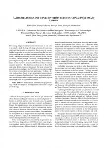
In Eq. (5) and (6), different values for ‘c’ and ‘d’ there are different forms of projective coordinates such as standard homogeneous coordinate, Jacobean coordinate and Lopez Dahab coordinate system. A good review over these projective coordinates are presented in [4]. Lopez Dahab projective coordinate system (selected in this work) requires less FF multiplications to perform SM operation [4], [11] and [17]. III. PROPOSED ARCHITECTURE FOR ECC The proposed hardware architecture implements the Lopez Dahab scalar multiplication algorithm 12], [17], shown as Algorithm 1. To implement Algorithm 1 for SM operation, the initial polynomial basis representation of binary elliptic curve parameters for proposed architecture have been selected from the NIST recommended document [18]. A generic structure for the implementation of SM on FPGA is illustrated in Fig. 1. Algorithm 1: Lopez Dahab Algorithm [12] and [17] Inputs: P = (xp, yp) GF (2m), K ← (ki-j, … , k1, k0) where, K is an j bit integer Output: k.p = (xq, yq) Step 1: Affine to LD Conversion/Initializations 1) X1 ← (xp) 2) Z1 ← 1 3) 4) X2 ← (Z2)2 5) X2 ← (X2+b) Step 2: Scalar Multiplication (SM) Loop Process for int i = j-2 down to 0 do 1) V1 ← (X1 Z2) 2) V2 ← (X2 Z1) 3) 4) R3 ← (Z1)2 5) R3 ← (R3)2 6) 8) Z1 ← (V3)2 9) 7) Z2 ← (Z2)2 11) V3 ← (b R3) 12) 10) V2 ← (xp Z2) 13) R3 ← (R3)2 14) X2 ← (V1 + V2) 15) If (i = 0 and K[i] = 1) swap (X1, X2), swap (Z1, Z2) end if end for Step 3: LD to Affine Conversion/Reconversion 1) V1 ← Inv(Z1) 2) V2 ← Inv(Z2) 3) 4) R1 ← (X1 V1) 5) V2 ← (X2 V2) 6) 8) V1 ← (xp + R1) 9) 7) R3 ← (R3 + yp) 11) V2 ← (V1 V2) 12) 10) V1 ← (V1 V3) 13) V2 ← (V1 V2) 14) R2 ← (V2 + yp) return KP = (xq, yq) = (R1, R2)
Z2 ← (X1)2
V3 ← (X1 Z1) Z2 ← (V1 + V2) V1 ← (V1 V2) R3 ← (X1)2 X1 ← (V3 + R3)
V3 ← Inv(xp) R3 ← (xp)2 V2 ← (xp + V2) V2 ← (V2 + R3)
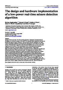
operands (Rd1 and Rd_2) from MU with the CU generated addressees (cw1 and cw2) and a single de-multiplexer (Dmux) which is used to perform write back (WB_Data) operation on MU with the specified register address (cw3). B. Finite Field Arithmetic and Logic Unit (FF-ALU) The proposed FF-ALU contains adder, squarer, multiplier and reduction units as depicted in Fig. 3.
Fig. 1: Proposed hardware architecture
The proposed architecture mainly consists of several units: a memory unit (MU), finite field arithmetic and logic unit (FFALU) and a finite state machine (FSM) based dedicated control unit (CU). The MU is designed to keep initial and final results whereas the FF-ALU is used to perform crypto arithmetic operations. The CU is designed to control all functionalities while implementing Algorithm 1. Finally, the detailed hardware architecture for each unit is further presented under the next subsequent sections: A. Memory Unit (MU) The memory unit for the proposed design consists of a 12 location Register array (R0-R11) with data size of ‘m’ bits and is depicted in Fig. 2. The main purpose to design this unit is to hold the input (xp, yp) and output (xq, yq) parameters and the intermediate results (X1, X2, Z1, Z2, V1, V2, V3, R1, R2, R3, R4 and R5) when implementing Algorithm 1 for the specified binary field (as discussed in introductory part of this article) ECC curve.
Fig. 3: Architecture for FF-ALU
Furthermore, two multiplexers (Mux_C and Mux_D) have also been used. However, the multiplexer (Mux_C) is used to select the appropriate input curve parameter and a source operand (Rd1) for different functional units whereas the Mux_D is used for routing purposes to select appropriate functional unit output for write back (WB_Data) operation. FF Multiplier: The performance of entire architecture mainly depends upon its multiplier [19]. The most commonly used FF multipliers are bit parallel and digit serial [20]. Bit parallel multipliers requires only single clock cycle to perform single multiplication [11] and [17] whereas digit serial requires ‘u/v’ clock cycles [21]. The term ‘u/v’ represents the total number of digits, ‘u’ represents the key length and ‘v’ represents the digit size. The typical examples for implemented bit parallel and digit serial multipliers include [11], [17] and [21] respectively. For further details over different FF multipliers, interested readers can consult [22].
Fig. 2: Architecture for memory unit (MU)
As shown in Fig. 2, proposed design for MU contains two multiplexers (Mux_A and Mux_B) which are used to read
In order to perform polynomial multiplication, we have implemented a bit parallel hybrid karatsuba multiplier as in [11] and [17]. A hybrid approach is achieved by implementing simple karatsuba multiplier for longer bits while for smaller bits simple partial products we have generated. For implemented hybrid approach all recursions (163, 82, 81, 41, 40, 21 and 20 bits) except the final recursion (11 and 10 bits) as presented in Fig. 4 are implemented by using simple karatsuba multiplier while partial products we have generated for final recursion.
Algorithm 3: Square Itoh Tsujii Inversion Algorithm
Input: A Output: A-1 = A×1/A = 1 Squares 1) 2) 3) 4) 5) 6) 7) 8) 9) 10)
Fig. 4: Hybrid karatsuba multiplier [11] and [17]
FF Reduction: To perform either two ‘m’ bit polynomial multiplication or one ‘ ’ bit polynomial squaring, the resultant polynomial would be ‘2×m-1’ bit. However, after each field squaring and multiplication, FF reduction is required [11]-[16]. In this work FF reduction is performed as implemented in [11] and [12] and here it is shown in Algorithm 2. Algorithm 2: FF Reduction [11] and [12] Input: polynomial D(x) with 325 bits Output: r(x) with 163 bits wide length M ← D[i] ⊕ D[i+163] ⊕ D[i+319] W ← D[i] ⊕ D[i+157] ⊕ D[i+160] 1) for 0 ≤ i ≤ 1 r[i] ← M ⊕ D[i+320] ⊕ D[i+323] 2) for i = 2 r[i] ← M ⊕ D[i+320] 3) for 3 ≤ i ≤ 5 r[i] ← M ⊕ D[i+160] ⊕ D[i+316] r[i] ⊕ D[i+317] 4) for i = 6 r[i] ← W ⊕ D[i+163] ⊕ D[i+313] ⊕ D[i+314] ⊕ D[i+316] 5) for 7 ≤ i ≤ 10 r[i] ← W ⊕ D[i+156] ⊕ D[i+163] ⊕ D[i+312] ⊕ D[i+314] 6) for 11 ≤ i ≤ 12 r[i] ← W ⊕ D[i+156] ⊕ D[i+163] ⊕ D[i+312] 7) for 13 ≤ i ≤ 161 r[i] ← W ⊕ D[i+156] ⊕ D[i+163] 8) for i = 162 r[i] ← W ⊕ D[i+156]
FF Inversion: In order to reduce hardware cost, inversion is achieved through squarer and multiplier units by implementing square Itoh-Tsujii inversion algorithm as presented in Algorithm 3. To compute inversion over GF(2163) 162 field squares followed by 9 field multiplications are needed. The implemented addition chain for Itoh-Tsujii inversion algorithm is 1, 1, 2, 4, 8, 16, 32, 64, 32 and 2.
2
R1 = A R2 = R12 R2 = R42 R2 = R12 R2 = R12 R2 = R12 R2 = R12 R2 = R12 R2 = R12 R2 = R12
Chain
Multiplications
1 1 2 4 8 16 32 64 32 2
R4 = R1×R2 R1 = R4×R2 R1 = R1×R2 R1 = R1×R2 R5 = R1×R2 R1 = R1×R2 R1 = R1×R2 R1 = R4×R2 R1 = R4×R2
C. Dedicated Control Unit (CU) The FSM based dedicated CU incorporates a total of 78 states to implement Algorithm 1. State 0 is an idle state while next 3 states (State 1 to 3) are responsible to implement the Step 1 of Algorithm 1. The Step 2 of Algorithm 1 (scalar multiplication) is core operation whereas to implement it 15 states are required. This step also requires 6 additional states which are further used to perform swapping between intermediate results for only one time. Finally to implement Step 3 CU constitutes a total of 53 states including FF inversion (inv-36 states) operation. In order to implement Algorithm 1, each FF adder, multiplier, squarer and reduction functional units produces result (operands fetch, execute and write back) in one clock cycle whereas each inversion requires 323 clock cycles to implement. Initializations (init) step of Algorithm 1 requires 3 clock cycles whereas SM loop process step of Algorithm 1 requires a total of 2436 clock cycles. Out of 2436 clock cycles, 2430 cycles are required for scalar multiplication and additional 6 cycles for swapping purposes. Similarly, reconversion step of Algorithm 1 requires only 987 clock cycles. Finally, the proposed crypto processor requires a total of 3426 clock cycles (T CCs) which can be computed by using Eq. (7). TCCs = init + 15(m-1) + 6 + 3(inv) +18
(7)
IV. IMPLEMENTATIONS AND RESULTS This section provides the implementation details of the proposed processor modeled in Verilog using Xilinx ISE 14.2. A. Input Curve Parameters The input parameters (xp, yp and b) of binary elliptic curves for polynomial basis representations are selected from NIST recommended document [18]. The hexadecimal notations is as follows: xp = 3f0eba16286a2d57ea0991168d4994637e8343e36 yp = 00d51fbc6c71a0094fa2cdd545b11c5c0c79764f1 b = 020a601907b8c953ca1481eb10512f78744a605fd
In order to analyze the performance of SM algorithm (Lopez and Dahab), alternate ‘0s’ and ‘1s’ are used as a secret key ‘K’ and its hexadecimal representation is as follows: K = 55555555555555555555555555555555555555555 B. Results and Comparisons Our proposed crypto processor for GF(2163) is synthesized over different Xilinx FPGA technologies for performance estimation i-e., Virtex 4 (xc4vlx80-12ff1148), Virtex 5 (xc5vlx50-3-ff1153), Virtex 6 (xc6vlx130t-3ff1156) and Virtex 7 (xc7vx690t-3ffg1930) respectively. The term throughput/area (i-e., 106/k.P(s)/slices) we have used to estimate the performance of proposed crypto processor. The corresponding synthesis results and comparison with state of the art are then presented in TABLE II. TABLE II. RESULTS AND COMPARISON WITH STATE OF THE ART OVER GF(2163) Area Information Time Information 106/ k.P Ref / Freq. k.P (sec)/ FPGA Slices LUT FF CC (MHz) (µs) Slices Proposed 6884 12293 2052 3426 64 53.5 2.71 / Virtex 4 Proposed 3636 8457 2052 3426 106 32.3 8.51 / Virtex 5 Proposed 3144 10160 2052 3426 127 26.9 11.82 / Virtex 6 Proposed 3657 10128 2052 3426 135 25.3 10.80 / Virtex 7 [13] / 6977 20154 3109 1339 103 13.0 11.02 Virtex 6 [15] / 16209 26364 7962 3010 153 19.5 3.14 Virtex 4
As shown in TABLE II, the main contribution for this work is to implement ECC based crypto processor on reconfigurable platform (FPGA). The proposed design utilizes lesser hardware resources in terms of FPGA slices (6884, 3636 and 3144) and requires only 53.5, 32.3 and 26.9 µs for one scalar multiplication (time for k.P) as it moves from Virtex 4 to Virtex 6 technology respectively. On Virtex 7 it requires only 25.3 µs for one k.P by utilizing 3657 slices. Furthermore, as shown in TABLE II, the achieved throughput/area (106/k.P(s)/slices) figures are 2.71, 8.51, 11.82 and 10.80 on Virtex 4, Virtex 5, Virtex 6 and Virtex 7 devices respectively. Although, on one side, achieved k.P time on Virtex 7 is 6% better than Virtex 6 whereas on the other side, the proposed design outperforms on Virtex 6 by achieving maximum throughput/area figure of 11.82. An FPGA based work presented in [15] achieves 14% higher throughput/area figure of 3.14 than the proposed work (2.71). On the other hand, the proposed work utilizes 58% lower area (slices 6884) than the work presented in [15] (slices 16209). Although, the received throughput/area figure in [15] is 14% higher while 58% lower hardware resource utilizations than [15] enable this work for constraint applications. Similarly, the work presented in [13] utilizes 55% higher hardware resources (slices 6977) than the reported work (slices 3144). Moreover, this work achieves 7% higher
throughput/area figure (11.82) than the work presented in [13] (11.02). In addition with both slices and throughput/area, the proposed work achieves higher operational frequency of 127MHz than the work presented in [13] where they achieved only 103 MHz on same Virtex 6. V. CONCLUSIONS In this paper, we have proposed an FPGA based crypto processor by implementing Lopez Dahab scalar multiplication algorithm. At arithmetic level, hybrid karatsuba multiplier and square version of Itoh Tsujii inversion algorithm have been implemented. We have implemented the crypto processor on different FPGA technologies i-e., Virtex 4, Virtex 5, Virtex 6 and on Virtex 7 for performance estimations and comparisons. The performance of proposed crypto processor is analyzed by a design metric i-e., throughput/area. The proposed processor outperforms on V6 with most relevant state of the art by achieving throughput/area figure of 11.82. In future, the proposed architecture can be optimized by adopting parallelism both at algorithmic and instruction level [23], [24], [25]. Furthermore, multiple methods can be used to improve the performance of existing FPGA architectures for cryptographic algorithms. Examples of such trends can be found in [26], [27] and [28]. Moreover, additional methods can be employed to ensure the satisfaction of timing properties for cryptographic algorithms [29], [30], [31]. REFERENCES [1]
G. C. Kessler, “An Overview of Cryptography,” Available at: http://www.garykessler.net/library/crypto.html. [2] N. Koblitz, “Elliptic Curve Cryptosystems,” Mathematics of Communication, vol. 48, no. 177, pp. 203–209, 1987. [3] V. Miller, “Use of Elliptic Curves in Cryptography,” In: Williams, H.C. (ed.) CRYPTO 1985,vol. 218 of the Series Lecture Notes in Computer Science, pp. 417–426, 1986. [4] D. Hankerson, A. Menezes, and S. Vanstone, “Guide to Elliptic Curve Cryptography,” New York, Springer, 2004. [5] F. Liu, “A Tutorial on Elliptic Curve Cryptography (ECC),” Brandenburg Technical University of Cottbus: Computer Networking Group, Available at: http://vanilla47.com/PDFs/Cryptography/Miscellenea/Eliptic%20Curve %20Cryptography/A_tutorial_of_elliptic_curve_cryptography.pdf. [6] Available at: https://www.certicom.com/news-releases/757-certicomlaunches-managed-certificate-service-to-secure-sensor-networks-andiot-applications. [7] Z. Dyka and P. Lagendorfer, “Improving the Security of Wireless Sensor Networks by Protecting the Sensor Nodes against Side Channel Attacks,” Wireless Networks and Security: Part of the series Signals and Communication Technology (SCT), pp 303–328, 2013. [8] T. Kasper, D. Oswald and C. Paar, “Side-channel Analysis of Cryptographic RFIDs with Analog Demodulation,” RFID Security and Privacy, vol. 7055 of the Series Lecture Notes in Computer Science , pp 61–77, 2012. [9] B. Harris, “Security Intelligence,” Available at: https://securityintelligence.com/platform-as-a-service-paas-cloud-sidechannel-attacks-part-i/. [10] M. Rashid, M. Imran and A. R. Jafri, “Comparative Analysis of Flexible Cryptographic Implementations,” In 11th IEEE International Symposium on Reconfigurable Communication-centric Systems-on-Chip (ReCoSoC), 2016, pp 1–6. [11] M. Imran, M. Kashif and M. Rashid, “Hardware design and implementation of scalar multiplication in elliptic curve cryptography
[12]
[13]
[14]
[15]
[16]
[17]
[18]
[19]
[20]
[21]
(ECC) over on FPGA,” In 6th IEEE International Conference on Information and Communication Technologies (ICICT), 2015, pp. 1– 4. Y. Zhang, D. Chen, Y. Choi, L. Chen, and S. B. Ko, “A High Performance ECC Hardware Implementation with Instruction-Level ,” Microprocessor and Microsystems., vol. 34, Parallelism over no. 6, pp. 228–236, 2010. Z. A. Benselama, M. A. Bencherif, N. Khorissi and M. A. Bencherchali, “Low Cost Reconfigurable Elliptic Crypto-hardware,” In 11th International Conference on Computer Systems and Applications (AICCSA), IEEE/ACS, 2014, pp. 788–792. G. Sutter, J. Deschamps, and J. Imana, “Efficient Elliptic Curve Point Multiplication Using Digit Serial Binary Field Operations,” IEEE Transaction on Industrial Electronics, vol. 60, no. 1, pp. 217–225, 2013. W. N. Chelton and M. Benaissa, “Fast Elliptic Curve Cryptography on FPGA,” IEEE Transactions on Very Large Scale Integration (VLSI) Systems, vol. 16, no. 2, pp. 198–205, 2008. R. Azarderakhsh and A. Reyhani-Masoleh, “Efficient FPGA Implementations of Point Multiplication on Binary Edwards and Generalized Hessian Curves Using Gaussian Normal Basis,” IEEE Transaction on Very Large Scale Integration (VLSI) System., vol. 20, no. 8, pp. 1453–1466, 2012. M. Imran, M. Rashid and I. Shafi, “Lopez Dahab based Elliptic Crypto Processor (ECP) over GF(2163) for Low-Area Applications on FPGA,” Accepted in International Conference on Engineering and Emerging Technologies, (ICEET), IEEE, Lahore, February 22-23 2018. NIST: Recommended Elliptic Curves for Federal Government Use, 1999, Available at: http://csrc.nist.gov/CryptoToolkit/dss/ecdsa/NISTReCur.pdf. A. R. Jafri, M. N. Islam, M. Imran and M. Rashid, “Towards an Optimized Architecture for Unified Binary Huff Curves,” Journal of Circuits Systems and Architectures, vol. 26, no. 9, pp. 1750178-1– 1750178-14, 2017. M. Imran and F. Shehzad, “FPGA based Crypto Processor for Elliptic Curve Point Multiplication (ECPM) over GF(2233),” Accepted in International Journal for Information Security Research (IJISR), vol. 7, 2017. Z. U. A. Khan, and M. Benaissa, “High-Speed and Low-Latency ECC Processor Implementation Over GF(2m) on FPGA,” IEEE Transaction on Very Large Scale Integration (VLSI) System., vol. 25, no. 1, pp. 165– 176, 2017.
[22] M. Imran and M. Rashid, “Architectural Review of Polynomial Bases Finite Field Multipliers Over GF(2m),” In 2017 International Conference on Communication, Computing and Digital Systems (C-CODE), IEEE, Islamabad, 2017, pp. 331–336. [23] S. Khan, M. Rashid and F. Javaid, “A high performance processor architecture for multimedia applications”, Computers and Electrical Engineering, In press, Available online: September 2017. [24] M. Rashid, L. Apvrille and R. Pacalet, “Application Specific Processors for Multimedia Applications”, In Proceedings of the 11th IEEE International Conference on Computational Science and Engineering, pp. 109-116, Brazil, 2008. [25] M. Rashid, L. Apvrille and R. Pacalet, “Evaluation of ASIPs Design with LISATek”, In Embedded Computer Systems: Architectures, Modeling, and Simulation, Springer, Lecture Notes in Computer Science,volume 5114/2008, pp. 177-186, 2008. [26] A. Asghar, M. Iqbal, W. Ahmed, S. Ali, H. Parvez, and M. Rashid, Exploring Shared SRAM Tables in FPGAs for Larger LUTs and Higher Degree of Sharing, International Journal of Reconfigurable Computing (IJRC), Article ID 7021056, 9 pages, 2017. [27] M. M. Iqbal, H. Parvez and M. Rashid, “Multi-Circuit: Automatic Generation of an Application Specific Configurable Core for Known Set of Application Circuits, Journal of Circuits, Systems and Computers (JCSC)”, Vol. 25, No. 09, 2016. [28] A. Asghar, M. Mazher Iqbal, W. Ahmed, M. Ali, H. Parvez and M. Rashid, Exploring Shared SRAM Tables Among NPN Equivalent Large LUTs in SRAM-Based FPGAs, IEEE International Conference on Field-Programmable Technology, China, 2016. [29] M. Rashid, M. W. Anwar, A. M. Khan, “Towards the Tools Selection in Model Based System Engineering for Embedded Systems - A Systematic Literature Review”, Journal of Systems and Software (JSS), Volume 106, Pages 150-163, 2015. [30] M. Rashid, M. W. Anwar, F. Azam, M. Kashif, “Exploring the Platform for Expressing SystemVerilog Assertions in Model Based System Engineering”, Volume 376 of the series LNEE, pp 533-544, 2016. [31] M. Rashid, M. W. Anwar and F. Azam, “Expressing embedded systems verification aspects at higher abstraction level: SystemVerilog in Object Constraint Language (SVOCL)”, Annual IEEE Systems Conference (SysCon), pp. 1-7, USA, 2016.