Applying LDPC Codes to the GPRS Fakheredine Keyrouz
Wen Xu, Tiago Gasiba
Data Processing Institute Munich University of Technology Arcisstrasse 21, D-80333, Munich, Germany
[email protected]
BenQ Mobile Heidenauplatz 1 D-81667, Munich, Germany
[email protected],
[email protected]
Abstract— The existing General Packet Radio Service (GPRS) currently uses the well-known convolutional code as a Forward Error Correction (FEC) mechanism, and the Viterbi algorithm for decoding. With the recent introduction of Multimedia Broadcast Multicast Services (MBMS), new applications that require more bandwidth and reliability are foreseen. It is known that the current GPRS system does not perform well enough without further modifications, therefore, more efficient information distribution schemes must be considered. To meet these increased requirements, especially for MBMS, we study the introduction of carefully designed LDPC codes at the physical layer. To allow the full benefit of the superior performance of LDPC codes for longer streams in MBMS, a modification in the GPRS protocol stack is proposed, where larger RLC/MAC blocks are allowed, and the impact of this adjustment on the traditional GPRS protocol stack is minimized.
I. I NTRODUCTION MBMS has been recently introduced into Radio Access Network (RAN) and GSM/EDGE Radio Access Network (GERAN). This new service offers an efficient way to transmit data from a single source to multiple destinations, thus decreasing the amount of data in the network. The expected MBMS traffic is believed to be in the area of traffic telematics, weather information, news broadcast, music streaming (web radio), video concert, sports replay, or file sharing. The use of common point-to-multipoint connections in a wireless broadcast scenario over GERAN necessary for the introduction of MBMS is not feasible without any modifications. According to [1], the impact of the required changes on the physical layer should be minimized and the reuse of existing features and protocols should be maximized. Due to the transmission mode used, commonly applied features such as the adaptation to the individual link quality by the use of adaptive coding and modulation schemes as well as power control are generally not possible. Consequently, at least some receiving entities will inevitably experience increased radio block loss rates. In addition, retransmission schemes based on common ARQ protocols are hardly realized in the wireless broadcast scenario due to the missing individual reverse links. Since in a broadcasting scenario with many receiving terminals the coding scheme of the traditional GPRS system cannot be adapted to the channel conditions of individual receivers, new coding and transmission schemes need be introduced to provide satisfying and reliable services to a large number of users within the serving area.
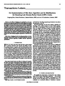
Now, Raptor codes, operating in the application layer, have been standardized [2], [3]. These codes allow to overcome the impairment of the lower-layer coding schemes. Due to their encoding and decoding schemes, these codes can be seen as a class of LDPC (low density parity check) codes which operate over the erasure channel. It is, however, widely known that codes which work directly on the symmetric channel and are decoded by exploiting soft information can achieve much better performance. However, soft information is generally not present in the upper-layers of the GPRS protocol stack. In order to compensate this, a so-called permeable layer receiver [4] has been devised which allows to forward partial information to upper layers for decoding. Although this scheme achieves a good performance it also has two major disadvantages. First, it requires a few changes in the protocol stack and second, its performance is not as good as a properly designed code in the lower layers. Recently, discussions and investigations related to, e.g. multi-carrier transmission especially for GERAN evolution are coming into focus. These new transmission schemes will necessarily require changes in the physical and upper layers. In this paper we investigate the applicability of carefully designed LDPC codes on the physical-layer of the GERAN system. This study allows us to understand the possible achievable gains by replacing the GSM convolutional code. It also gives us some insight into good error control schemes for future generation systems. II. OVERVIEW OF P REVIOUS W ORK A. Protocol Stack Fig. 1 depicts the typical processing of packets at the various stages of the GPRS. After optional header compression at the SNDCP layer and framing at the Logic Link Control (LLC) layer, the resulting Service Data Unit (SDU) at the Radio Link Control (RLC) layer is divided into equally sized segments, each of length L bytes. The segment size depends on the applied coding scheme at the physical layer. Each segment is then mapped onto the data part of a Radio Link Control/Medium Access Control (RLC/MAC) block. An Up-link State Flag is block-encoded into the RLC/MAC block header. After this process, the RLC/MAC block is appended with a Cyclic Redundancy Check (CRC) sequence and also termination bits in the tail, and is then encoded. The GSM channel encoder is a well-known convolutional code. The encoded block of
PH
User data Segment
...
Info
FSC
FH
Segment
...
Network layer SNDCP layer Segment LLC layer
Segment
RLC/MAC layer
signaled with erasures, and finally RS decoding is applied columnwise [5]. This scheme is much more efficient than repetition scheme, mainly because the RS code is an MDS code and the code rate ( K N ) can be easily adapted and is not 1 limited to M . III. U SING LDPC C ODES IN THE P HYSICAL L AYER
H
data
A. Overview
C T Physical layer
LDPC Encoder
Convoluional Encoder
Encoded block
114
114
114
114
Fig. 1. Introducing LDPC codes to the GPRS protocol stack
constant size 456 bit, obtained through appropriate puncturing, is then interleaved and divided into four bursts, which are mapped onto the assigned time-slot in four successive TDMA frames. Due to the poor performance of convolutional codes in the presence of burst-errors, interleaving is performed in order to combat these types of errors and, thus, to increase the system performance. At the receiver, the four consecutive transmission bursts are reassembled and de-interleaved and standard Viterbi-Decoding is performed on each of the reassembled blocks. If residual bit errors are detected by using the CRC sequence in RLC/MAC block tail, the respective block is commonly declared as lost to avoid error propagation across layers.
Newly rediscovered LDPC codes, originally investigated by Gallager [6] in 1963, are nowadays known to achieve much better performance than convolutional codes, and even capable of performing better than turbo codes [7], while maintaining a low decoding complexity (e.g. linear in the block size). In section II-A, the GPRS protocol stack was shown to use a rate 1/2 convolutional encoder followed by a puncturing device to adapt the code parameters. The performance of such a system can be improved by replacing the convolutional encoder and the puncturing device with an LDPC encoder, as shown in Fig. 1, with appropriate code parameters, such that no puncturing device is needed anymore. To maintain compatibility with the current systems, only the channel encoder is replaced, and the remaining protocol stack remains untouched. In particular, its parameters and operation modes (coding schemes) are kept the same, such as the number of input bits and output bits. The LDPC encoder is, therefore, restricted to encoding short block lengths and to be a rate 1/2 encoder for CS-1. Necessary code parameters for system compatibility are given in Table I, where the LDPC code parameters column represents an (n, k) block code, with k being the number of input bits and n the number of output (encoded) bits. Notice that the block code dimensions are adjusted to fit the GPRS system and puncturing is no more required. This adopted solution has a small impact in the current GPRS protocol stack.
B. Previous Proposals In order to increase system reliability, different schemes have been proposed. The most important schemes are the repetition scheme and the Reed-Solomon coding scheme. In the first scheme, the RLC-MAC blocks are blindly repeated M times and forwarded to the physical layer channel encoder (GSM convolutional encoder).At the receiver two different decoding methods can be employed: 1) each RLC/MAC block is individually decoded and dropped if the CRC fails, 2) code combining is applied, where each replica of the RLC/MAC block is bitwise added, and the resulting block is then decoded. The second technique obviously brings more gains than the first. Alternatively, an outer Reed-Solomon (RS) code can be employed at the RLC/MAC layer. In this case K RLC/MAC blocks of length L are stacked into a matrix, whereby RS code is applied L times to each column each time computing N −K additional redundant symbols (per column). The N RLC/MAC blocks are then forwarded to the physical layer, as usual. At the receiver, after Viterbi decoding, the blocks are stacked again in a decoding matrix, whereby missing RLC/MAC blocks are
TABLE I GPRS
CODING SCHEMES .
Coding Scheme
Code rate
Code bits
Data rate [kbps]
LDPC Code Parameters
CS1 CS2 CS3 CS4
1/2 2/3 3/4 1
456 588 676 456
9.05 13.4 15.6 21.4
(456, 228) (588, 294) (676, 338) −
The main impairment in using the described structure is the fact that short LDPC codes are required. Careful design of such codes is necessary in order to achieve improved system performance. In the next section, we will give a brief overview of new achievements and breakthroughs in this field and also give some insight on how to generate short block length LDPC codes, using the recent techniques. A number of methods have been developed for creating capacity-approaching LDPC codes of very large block lengths [8]–[11]. The general initiative is to analyze the behavior of ensembles of codes, and discover those with good
average performance. Then, based on concentration results, which were demonstrated to hold for large block lengths, random codes are guaranteed to have good performance as well. This is due to the fact that the performance is concentrated around the average performance, and hence for enough block length, a good code can be generated with high probability by randomly choosing any code in the ensemble. On the other hand, the analysis that holds for large block lengths is not helpful for smaller block length codes (under 10, 000 message bits). In fact, experimental results show that for small block lengths, the difference in performance can be pretty large [11]. However, short codes are necessary for applications that require the reliable exchange of short and frequent data streams, which are to be encoded to avoid undesirable overheads, delays and complexity. The necessity of such codes in the context of digital and mobile communication, some of which want to transmit data over binary symmetric channels and more difficult channel models, emphasize the importance of finding suitable short codes over such channels. In [10] and [8], the authors proposed a heuristic approach that compares small block length codes generated randomly and identifies the better ones with high probability. This method is based on the intuition that small cycles hinders the decoding process because the independence assumption is violated and the errors propagate faster than they can be corrected. The method compares the codes based on their girth1 distribution, and selects the best ones according to some criteria. It has been shown that, in practice, their method generates short block length codes that perform well in the binary symmetric channel. Prior to this girth conditioning technique, very little improvement was made in the direction of developing an efficient and accurate method to evaluate and select small blocklength codes. Recent work implies that their method applies best to the BSC channel, but it can also be applied to the erasure channel with relative success. In [12], it is heuristically shown that the degree distribution of the variable and check nodes of the bipartite graph representing the code considerably influence its performance. The check nodes degree was fixed to a constant number, and the optimal degree distribution for the variable nodes was found by solving a linear program. The linear program simulates the decoding algorithm. More specifically, the linear constraint node degree distribution forces the probability of an erroneous message sent by a variable node to decrease after each subsequent round of the decoding process. More recently, [13] addressed the problem of code construction and proposed a rate-flexible reduced error floor LDPC matrix design methodology. Clear theoretical connections between cycles, stopping sets, and codewords are established. A new metric called Extrinsic Message Degree (EMD) was introduced which measures cycle connectivity in bipartite graphs. Using an easily computed EMD estimate, a Viterbilike algorithm was proposed to selectively avoid cycles and 1 The girth of a node in a graph is defined as the size of the smallest cycle containing that node.
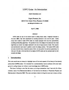
increase minimum stopping set size. This algorithm yields codes with error floors that are orders of magnitude below those of girth-conditioned codes described previously by [8]. The resulting codes have good waterfall-region and errorfloor performance over a wide range of code rates and block sizes. A new metric called extrinsic message degree (EMD) measures cycle connectivity in bipartite graphs. Using an easily computed estimate of EMD, we propose a Viterbi-like algorithm that selectively avoids cycles and increases stopping set size. This algorithm yields codes with error floors that are orders of magnitude below those of girth-conditioned codes. In this work, we adopted this Viterbi-like technique to generate parity check matrices and perform encoding. B. LDPC Codes A (n, k) low-density code is defined as a code of block length n, with a parity check matrix H like that of Fig. 2, whereby each column (row) contains a small number of 1’s, i.e. the density of 1’s in the matrix is low. In the same figure we also show the normal graphical representation of the code, also known as the Tanner graph. This bipartite graph contains on the left message nodes and on the right check nodes. A message node corresponds to a bit that is transmitted through the channel, while a check node corresponds to a code constraint, i.e. the sum of all the message bits connected the check node must be zero. There are two classes of LDPC codes: regular and irregular. On the one hand, in regular LDPC codes all columns (rows) of the H matrix have the same number of 1’s. The design rate of the code is given by R = 1 − ddvc , whereby dv (dc ) is the degree of a variable (check) node respectively. On the other hand, the node degrees irregular LDPC codes are not fixed, but are chosen according to some distribution. The design rate ¯ of irregular LDPC codes is R = 1− dd¯vc , whereby d¯v (d¯c ) is the average degree of a variable (check) node respectively. Notice that the LDPC code in Fig. 2 is an irregular code. The graph Variable nodes v1 v2
Constraint nodes c1
v3 c2
V1 V2 V3 V4 V5 V6 V7 V8 V9
1 0 0 H= 0 0 1
0 1 0 0 1 1
1 1 0 0 1 0
0 0 1 1 1 0
1 1 0 1 0 0
0 1 1 0 1 0
0 1 0 1 0 1
0 0 0 1 0 1
1 0 0 0 1 1
v4 C1 C2 C3 C4 C5 C6
v5
c3
v6
c4
v7 v8 v9
c5 c6
Fig. 2. Matrix and bipartite description of a (9,3) irregular LDPC code
and the parity check-matrix are related to each other: columns represent variable nodes and rows represent check nodes. For every 1 in H, there is an edge between the corresponding pair of nodes.
1) Code Construction: By definition, a variable node set is called a stopping set of size d, if it has d elements and all its neighbors are connected to it at least twice, e.g. the variable node set {v1 , v5 , v7 } in Fig. 2 is a stopping set of size 3. All stopping sets of small size are problematic and good LDPC codes have only stopping sets of very large size. Thus, in order to generate codes well-suited to iterative decoding, the size of minimum stopping set should be increased. In his original work, Gallager [6] already developed an algorithm to condition the graph so that all small cycles have enough neighbors to provide useful message flows. This is accomplished by the Extrinsic Message Degree (EMD) parameter. An extrinsic constraint node of a variable node set V , is a constraint node that is singly connected to this set. The extrinsic message degree (EMD) of a variable node set V is the number of extrinsic constraint nodes of this variable node set. In this work we use an algorithm introduced in [13] that targets the elimination of small cycles with low EMD and that ensures that short cycles contain at least a given minimum number of ’extrinsic’ paths. These small cycles are significant contributors to errors at high SNR, i.e. so called error floors. As a consequence, all cycles less than a given length have an EMD greater than a given value, thus increasing the smallest stopping set size. This algorithm also increases the minimum distance dmin because codeword sets are special cases of stopping sets. To provide an easily computed EMD metric, the Approximate Cycle EMD P (ACE) is introduced. The ACE of a length th 2d cycle is i (di − 2), where di is the degree of the i variable in this cycle. We also say that the ACE of a degree-d variable node is d − 2 and the ACE of any constraint node is 0. Notice that ACE is an upper bound on EMD. An LDPC code has property (dACE ,ηACE ), if all the cycles whose length is 2dACE or less have ACE values of at least ηACE . Details about the Viterbi-like ACE algorithm can be found in [13]. In our systematic codes, information bits come before parity bits. We assign column nodes such that degree decreases monotonically (i.e., di ≥ dj if i < j). Because high degree nodes converge faster, this arrangement provides more protection to information bits than to parity bits. Once the parity check matrix passes the ACE test, it will have the form H = [P T | I] where P and I correspond to the parity and identity matrices respectively. Following the ACE test, a Gaussian elimination process takes place ensuring that the n − k columns of P are linearly independent, and hence guarantees that the H matrix has full rank and the design rate is achieved. 2) Encoding: The binary LDPC codes used in this work are defined over the Galois field GF(2). These codes can be expressed as the set of solutions to a parity-check equation, C(H) := {c ∈ GF (2) : HcT = 0T },
(1)
where H is the (n − k) × n parity-check matrix of the code, as defined previously.
Each parity check equation is just a series of binary XOR operations. To generate systematic LDPC codes, we append to every k source symbols ~s, the parity part ~xp = ~s · P . This corresponds to an encoding complexity of k × (N − k), i.e. quadratic in the block length, O(k 2 ). 3) Decoding: LDPC codes have achieved such an importance, not because of the codes themselves, but due to their decoding algorithm, i.e. Belief-Propagation (BP). In the following we will very briefly review the major steps of BP decoding required in order to decode a received codeword. Initialization Prior (channel) LLRs are computed as: LLRCh (yi ) , log
p(yi |x=1) p(yi |x=−1) ,
where y1 ,...,yn are n noisy observations of a binary random variable (one codeword). Messages from variable to check nodes Each variable node sends extrinsic information to the check nodes given by X
LLRvi 7→cj = LLRCh (yi ) + j0∈
LLRcj0 7→vi ,
col(i)\j
whereby col(i) denotes the row indexes of column i in the parity-check matrix which have non-zero entries. Notice that the computation of the message from vi to cj excludes the message coming from check node j. Messages from check to variable nodes Each check-node sends extrinsic information to the variable nodes given by LLRcj 7→vi = 2 tanh(−1)
Y
i0 ∈row(j)\i
LLRvi0 7→cj , tanh 2
whereby row(j) denotes the column indexes of row j in the parity-check matrix which have non-zero entries. Notice that the computation of the message from cj to vi excludes the message coming from variable node i. Soft Outputs The soft outputs are computed as follows:
LLRSof t (yi ) = LLRCh (yi ) +
X
LLRcj 0 7→vi .
j 0 ∈col(i)
The hard-decision values are given by the conventional signal function:
¡ ¢ yˆi = sign LLRSof t (yi ) For a detailed explanation of BP decoding we refer the reader to [14].
4) Decoding complexity: The decoding complexity per bit is given by the number of iterations performed times the operation per bit per iteration, i.e. Cbit = Nit × dv × {Vn + dc × Cn }, where Cbit denotes the complexity per bit, Nit is the number of iterations, dv and dc are the variable and check node degrees respectively, Vn and Cn are the complexities of the variable node and check node decoders respectively. The total decoding complexity is the sum of the N -bit codeword complexities. Since the per-bit decoding complexity of the BP algorithm is independent of the block length, the total complexity of the decoder is linear in the block length, O(N ). C. Reed-Solomon Codes RS codes belong to a class of powerful cyclic error correcting codes, the BCH codes. They are MDS (Maximum Distance Separable) codes, are good burst error correcting codes, and operate over GF(2m ). It is trivial to prove that in order for a code to be MDS, it must necessarily be non-binary and be represented by a dense generator matrix. An overview of the important code parameters is given in Table II, whereby ν represents the number of erasures and t the number of errors in the received codeword. Note that the block length of the code is determined by the size of the Galois Field used while the code rate is essentially determined by the number of parity symbols (source symbols) used. TABLE II R EED -S OLOMON CODE PARAMETERS . Block length Number of parity symbols Minimum distance Correcting capabilities Code rate
n = 2m − 1 n − k = 2tmax dmin = 2tmax + 1 ν + 2t ≤ dmin k n
We will be interested only in the erasure correction capabilities of the RS code and, therefore, assume that t = 0, i.e. only erasures occurs. In the following we briefly describe RS codes encoding and decoding in a simple way which is most suited for erasure correction, and also some code modifications that are required for MBMS like shortening and puncturing. 1) Encoding: It is well known that any polynomial f (x) in < 7→ < of degree k can be fully specified by k distinct points f (x1 ), · · · , f (xk ). This property also carries over to finite (Galois) fields. A Reed-Solomon code is a mapping GFk (2m ) 7→ GFn (2m ) which is given by a polynomial function f (x) = a0 + a1 x + a2 x2 + · · · ak−1 xk−1 of degree k. The coefficients ai of this function correspond to the source symbols and the n output symbols correspond to the evaluation of the function at n distinct points αi with i = 0, · · · , n − 1 whereby α represents a primitive element of GF (2m ). Representing the j’t output symbol by bj , we have that bj = f (αj ). The set of output symbols b can be more
conveniently represented by ¡ 0 ¢0 b0 α ··· .. .. . = . ¡ n−1 ¢0 bn−1 α ···
a0 . · . . . ¡ n−1 ¢k−1 ak−1 α
¡
α0
¢k−1
(2)
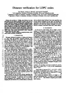
Note that the generator matrix of the RS code in Equ. 2 builds a non-systematic code and is has a Vandermonde structure. A simple modification to the encoding procedure is possible such that a systematic code can be built. 2) Decoding: After transmission of a RS codeword through an erasure channel, only a sub-set of the original output symbols are received. More precisely this means that we receive a set of r points b00 = f (β0 ), · · · , b0r−1 = f (βr−1 ), whereby βl corresponds to the αj of the received symbol. Since we know the degree of the function f (x), decoding now can be thought of performing an interpolation such as to find the coefficients a0i that minimize the squared error: ¯ ¯2 £ 0 ¤ a0 , · · · , a0k−1 = arg min∀aj ¯f (αj ) − f (β l )¯ . (3) Assuming that we have no symbol errors, this procedure is easily achieved by eliminating the rows of the generator matrix corresponding to symbols that were erased, i.e. building a matrix G0 , and inverting the system of equations b0 = G0 a. In general, due to the fact that the generator matrix of the code is dense, the encoding and decoding of Reed-Solomon codes has quadratic complexity, i.e. O(k 2 ) 3) Code modifications: In order to obtain Reed-Solomon codes with flexible encoding parameters, while using a single base mother code, the RS codes can be modified in the following way: 0 0 • Shortened A smaller RS code with parameters RS(k , n ) 0 can be obtained by setting kk information symbols to known values both to the encoder and decoder. These values are usually set to zero and are not transmitted. • Punctured Puncturing a RS code increases the code rate and reduces the correction capability of the code. To puncture a RS code we simply do not transmit some parts of the codeword. The punctured symbols are equivalent to erased symbols at the decoder. IV. N EW RLC/MAC B LOCK D ESIGN As already noticed in section III-A, the main performance limitation steams from the fact that the best known LDPC codes have very large block lengths. In order to take full advantage of large LDPC codes, the lower-level protocol stack needs to be redesigned. As a consequence, there is an increase in decoding latency. In order to make a fair system comparison, we have selected the LDPC code size to match the proposed schemes using outer Reed-Solomon codes [5]. Fig. 3 shows a possible modification of the protocol stack to incorporate larger LDPC codes. The block check sequence is computed as before and has also the same length. LLC segments are concatenated to form one sub-segment. New Block Check Sequence (BCS) and Segment Number (SN) are added so that the total subsegment length is (456−USF) bits. Since the
PH
User data SNDCP layer Segment
FH
Info ...
Extended RLC/MAC Block
...
Segment
...
Segment LLC layer
FSC
...
A. AWGN Channel
...
RLC/MAC layer
data segment S# BCS ... data segment S# BCS (456-USF) bits
...
Physical layer
(456-USF) bits LDPC Encoder
Systematic data
USF
Parity
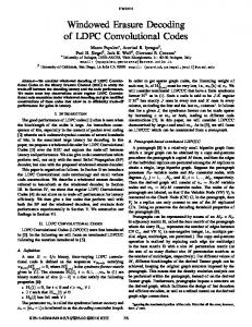
Using the Viterbi-like algorithm to construct short block length irregular LDPC codes, we have generated (2000, 1000) LDPC codes with irregular degree distributions (given in [9]), and with maximum variable node degree dv = 10. All cycles of the generated irregular codes of length up to 2dACE have ACE of at least ηACE . For each received codeword, up to 40 iterations (for irregular codes) and 100 iterations (for regular codes) have been performed. Fig. 4 shows the simulation results. The irregular LDPC code obtained using the ACE
114 114 114 114 ... 114 114 114 114
...
114 114 114 114
these codes to the GPRS system and show results for the two different proposed protocol stack modification schemes.
USF
0
10
100 iter Regular 40 iter Irregular, random (dv = 10) 40 iter Irregular, ACE(9,4)(dv = 10)
USF −1
10
1
2 ...
TDMA 4.615ms
8
1
2 ...
8
...
TDMA 4.615ms
1
2 ...
8 −2
TDMA 4.615ms
10
time
−3
Fig. 3. The proposed GPRS stack for extended RLC/MAC block length.
BER
10
−4
10
−5
10
LDPC encoder does not require any termination bits which are used by the convolutional code to return the trellis to the “all-zero state”, we use these tail bits for regular data. Several subsegments form the input to the LDPC encoder. At the output of the encoder, an Up-link State Flag (USF) is added to every (456−USF) bits, and the resulting 456 bits are divided into bursts of 114 bits each, and mapped over consecutive TDMA frames, as previously. It is technically crucial to append the Up-link State Flag to every transmitted data block, since the USF is used to re7serve the up-link for different MSs so that collision on up-link channel is prevented. The USF in this case is encoded using the block code defined in [15]. Furthermore, there is a strong need to employ systematic codes, although non-systematic FEC codes allow a higher flexibility. Systematic codes employed here, leave the data unchanged, it becomes therefore possible to process the data at the received by the user equipment, which has not implemented an FEC decoder. In this case, any missing block could be provided by a fast retransmission service. More importantly, long interruptions and temporal higher SDU FER may disable the non systematic FEC decoding. In this case, the received non-systematic encoding symbols are useless, while for systematic codes, the received source symbols can still be processed and it can be useful to help detecting missing content. V. S IMULATION R ESULTS We first show simulation results of well designed LDPC codes operating on the AWGN channel, based on code construction method as presented in section III-A. Then, we apply
−6
10
−7
10
−8
10
0
1
2
3
4
5
6
7
8
9
10
SNR [dB]
Fig. 4. AWGN performance comparison of (2000, 1000) regular and irregular LDPC.
method shows reduced error floor compared to the irregular random codes. Note that, with less decoding iterations, the irregular LDPC code outperforms the regular LDPC code for low SNR. B. GPRS Operating with LDPC Code Using the protocol stack changes proposed in section IIIA, the short length LDPC codes have been evaluated against the current system, using the Viterbi-like decoding algorithm SOVA [16] and the more advanced BCJR algorithm [17], over several channels. Fig. 5 shows the simulation results for the Bit-Interleaved Rayleigh Fading (BIRF)channel. In Table III, several more simulation results are summarized showing the superiority of the proposed scheme against all the previous schemes. Of particular interest is the Typical Urban Channel with an average vehicle speed of 3 km/h (TU-03). Over this channel, at a typical signal-to-noise ratio Eb /N0 of 10 dB, gains in the order of 1.5 dB for CS-1 and in the order of 2.8 dB for CS-2 are achieved.
0
0
10
10 BER LDPC SER LDPC BER CC BCJR SER CC BCJR BER CC SOVA SER CC SOVA
−1
10
Repetition scheme Outer RS (2560,1280) LDPC (5328,1332) −1
10 Segment Error Rate
Bit/Segment Error Rate
−2
10
−3
10
−2
10
−4
10
−3
10 −5
10
−4
10 −6
10
−7
10
−5
0
1
2
3
4
5
6
7
Eb/No [dB]
10
0
1
2
3
4
5
6
Eb/No [dB]
Fig. 5. Coding Scheme 1 (CS-1) Bit and Segment Error Rate over the bitInterleaved Rayleigh Fading (IRF) channel using LDPC codes, and Convolutional Codes (CC) decoded using BCJR/SOVA.
Fig. 6. Extended (5328, 1332) LDPC Segment Error Rate (SER) performance over the Block-Interleaved Rayleigh Fading (BIRF) channel using Coding Scheme 1.
TABLE III P ERFORMANCE COMPARISON FOR SEVERAL CHANNEL TYPES , DIFFERENT CODING SCHEMES AND DECODERS
Channel
Coding Scheme
Eb /N0
BER
Comparison
AWGN
CS-1
0.5 dB
1.8 × 10⁻⁵
BIRF
CS-1
8.0 dB
4.0 × 10⁻⁷
TU-03 TU-03
CS-1 CS-2
10.0 dB 10.0 dB
1.0 × 10⁻⁴ 6.0 × 10⁻³
∆SOVA = 1.8 dB ∆BCJR = 0.87 dB ∆SOVA = 1.3 dB ∆BCJR = 1.6 dB ∆SOVA = 1.5 dB ∆SOVA = 2.8 dB
C. LDPC Code with New RLC/MAC Block Design The GPRS protocol stack using longer LDPC codes was also evaluated against the proposal based on outer ReedSolomon codes and the physical layer repetition scheme [5]. Fig. 6 shows the simulation results for the case of a ReedSolomon code with parameters (16, 8). We observe a performance gain of about 1.4 dB at an Eb /N0 of 2.7 dB and a large gain of about 3.5 dB compared with simple repetition scheme is achieved. Also notice that, over the BIRF channel, virtually all users with low Eb /N0 (about 3 dB) can expect a download speed of about 36.2 kbps using four time-slots at an IP-loss rate of 10−4 for IP packets of 500 byte of size. VI. C ONCLUSIONS In this paper we have presented two different methodologies for applying LDPC codes to the GPRS protocol stack. In one scheme, we have used the LDPC code as the operating channel coding scheme, replacing the GPRS convolutional code. Our choice was motivated by the fact that the underlying codes in LDPC codes are very simple parity-check relationships, so the potential for complexity reduction compared to other
advanced FEC codes, like Turbo codes, is significant. We have generated, thus, carefully designed irregular LDPC codes using state-of-the art algorithms that selectively avoid cycles and increase the minimum stopping set size. These codes have than been applied to the GPRS protocol stack and integrated into a GSM/GPRS simulator. The performance of such codes was investigated over distinct classes of wireless channels (AWGN, IRF, BIRF, TU03). Comparison with the current traditional GPRS system, demonstrated the better performance of LDPC codes decoded via the belief propagation algorithm in comparison with the standard GPRS convolutional code decoded using both SOVA and BCJR. A new design to the GPRS RLC/MAC block was proposed that overcomes the main limitation of the first approach: short block codes. By using a longer block codes, the superior performance of irregular LDPC codes was again obvious. Comparison of our proposed system operating with rate 1/4 irregular LDPC code, with the system using the concatenation of outer Reed-Solomon code on RLC/MAC blocks and inner convolutional code, has shown that our design requires about 1.4 dB less transmit power to achieve a segment error rate SER of 10−4 . Similar design can obviously be applied to EGPRS. In comparison to the GMSK, three times data are processed with the 8-PSK based coding schemes, meaning that more gains are expected for 8-PSK based coding schemes when LDPC code is used. For future work it might be interesting to consider using the LDPC code in the application layer, especially in collaboration with a Permeable Layer Receiver [4], where iterative decoding becomes possible. R EFERENCES [1] T. G. T. GP-0300002, “Performance of MBMS Radio Bearers,” Nokia, TSG GERAN MBMS Workshop, Espoo (Finland), May 2003.
[2] 3GPP TSG-SA WG4 S4-AHP238, Specification Text for Systematic Raptor Forward Error Correction, PSM SWG, Sophia Antipolis, France, Apr. 2005. [3] M. Luby, M. Watson, T. Gasiba, T. Stockhammer, and W. Xu, “Raptor codes for reliable download delivery in wireless broadcast systems,” in Proc. CCNC’06, IEEE Consumer Communications and Networking Conference, Las Vegas, NV, January 7-10 2006, (accepted for publication). [4] H. Jenkac, T. Stockhammer, and W. X, “Permeable-layer receiver for reliable multicast transmission in wireless systems,” in Proc. WCNC’05, IEEE Wireless Communications and Networking Conference, New Orleans, LA, March 2005. [5] H. Jenkac, G. Liebl, T. Stockhammer, and W. Xu, “Flexible outer ReedSolomon coding on RLC layer for MBMS over GERAN,” in Proc. of VTC Spring 2004, Milan, May 2004. [6] R. G. Gallager, Low Density Parity-Check Codes, MIT Press, Cambridge, MA, 1963. [7] C. Berrou, A. Glavieux, and P. Thitimajshima, “Near Shannon limit error-correcting coding and decoding,” in Proc. ICC’93, Geneve, Switzerland, May 1993, pp. 1064–1070. [8] Y. Mao and A. Banihashemi, “A heuristic search for good low-density parity-check codes at short block lengths,” in International Conf. on Comm., vol. 43, Helsinki,Finland, June 2001. [9] T. Richardson, A. Shokrollahi, and R. Urbanke, “Design of capacityapproaching irregular low-density parity-check codes,” in IEEE Trans. Inform. Theory, vol. 47, 2001, pp. 619–637. [10] Y. Mao and A. Banihashemi, “Design of good LDPC codes using girth distribution,” in IEEE International Symposium on Information Theory, Italy, June 2000. [11] T. Richardson and R. Urbanke, “The capacity of low-density parity check codes under message-passing decoding,” in IEEE Trans. Inform. Theory, vol. 47, 2001, pp. 599–618. [12] M. Luby, M. Mitzenmacher, M. Shokrollahi, and D. Spielman, “Improved low density parity check codes using irregular graphs and belief propagation,” in IEEE Trans. Inform. Theory, vol. IT-47, Feb. 2001, pp. 585–598. [13] C. Jones, “Constructions, applications, and implementations of lowdensity parity-check codes,” Phd Thesis, Department of Electrical Engineering, University of California, Los Angeles, 2003. [14] F. Keyrouz, “Advanced Channel Coding for MBMS,” Master Thesis, Institue of Communications Engineering, Technische Universitt Muenchen, Germany, 2004. [15] GSM Specification Series 03.64, V6.0.0, page 24, www.3gpp.org/ftp/Specs, 1998-04. [16] J. Hagenauer and P. Hoeher, “A Viterbi Algorithm with soft-decision outputs and its applications,” in Proc. IEEE Globecom Conf., Dallas, TX, November 1989, pp. 1680–1686. [17] L. Bahl, J. Cocke, F. Jelinek, and J. Raviv, “Optimal decoding of linear codes for minimizing symbol error rate,” in IEEE Trans. Inform. Theory, vol. IT-20, Mar. 1974, pp. 284–287.