The plan identifying all of these activities is called software development process. ..... application development, when a project manager determines the current ...
Applying System Dynamics to Scenario Based Software Project Management MÁRCIO DE OLIVEIRA BARROS CLÁUDIA MARIA LIMA WERNER GUILHERME HORTA TRAVASSOS COPPE / UFRJ – Computer Science Department Caixa Postal: 68511 - CEP 21945-970 - Rio de Janeiro – RJ Fax / Voice: 5521 590-2552 {marcio, werner, ght}@cos.ufrj.br Abstract Complex software development is a risky job. The number of unsuccessful projects largely surpasses the number of successful developments. Many studies relate this situation to non-technical problems, especially to inadequate project management. Scenario based software project management is an extension of the risk management paradigm that uses system dynamics abstract models to describe potential problems that can affect a software project. Dynamic models are also used to describe possible resolution strategies applicable to eliminate or reduce the potential problem impact over the software project. Scenarios are defined by integrating combinations of these models to a project model. The project model is based on Abdel-Hamid and Madnick’s software project model, which uses system dynamics notation to formulate several relations among development staff, software products, quality, project control and planning. The original model was adapted to allow a fine-grained description of project tasks, personnel abilities, and error propagation. The modified model also allows operational project monitoring. The proposed technique allows the development of a standard problem and resolution strategy model library, to be integrated to new and ongoing projects. These models are abstract, in the sense that they cannot be directly simulated. The simulation is only accomplished when they are integrated to the project model. Their variables and equations affect the project model behavior, replicating the impact promoted by the problems and resolution strategies that they describe. The system dynamics notation was expanded to allow the definition of the integration interface. Scenario analysis is a valuable tool to predict project results, such as cost, schedule and effort, in face of several combinations of problems and resolution actions. System dynamics complements the technique, describing nonlinear relationships and feedback loops among model elements. Keywords: Risk management, project management, software process modeling 1 Motivation The state of practice and contemporary literature report the persistence of a recurrent problem in software development: most projects use more resources than planned, take more time to be concluded, provide less functionality and less quality than expected. Software
unsuccessful stories can be found in several case studies and experiments documented over the last decades (Gilb, 1988) (Neumann, 1995) (Charette, 1996). Two different philosophical paradigms relate factors that are responsible for the continuing software faults in industry. The first one relates software development problems to technological limitations, augmented by the increasing complexity of current software projects (Augustine, 1982). The second philosophical paradigm transfers the responsibility to management problems, bad communication, and difficulties in handling the uncertainties that are present in innovative, complex or large software projects (Genutchten, 1991) (Brown, 1996) (Royce, 1998). In order to conduct a successful software project, we must understand the scope of the work that needs to be done, incurred risks, required resources, activities to be accomplished, milestones to be tracked, the effort to be spent, and schedule to be followed (Pressman, 1992). The plan identifying all of these activities is called software development process. Its management is called software project management. The techniques currently applied to software project management are dated from the 1950’s and 1960’s, developed to allow the accomplishment of advanced military projects, such as the Polaris project. These techniques include work breakdown structures, PERT/CPM charts, Gantt diagrams, and crashing. They are based on a set of fundamental assumptions, necessary for their accuracy (Charette, 1996). Some of these techniques require that projects have clear and delimited objectives, there exists at least one solution to the problem at hand, development time and resources can be precisely stated before the project starts, the operational environment is well known and defined, and that quality metrics can be quantified for the project. Due to many successes resulted from using these techniques in large projects, project managers tend to passively take their underpinning assumptions for granted in every project (Charette, 1996). This misconception is very common in software project management. Current project management techniques’ baseline assumptions require a project behavior to be known from the beginning. The development of projects for innovative application domains with high requirement volatility, the need for domain integration to achieve several objectives, ambiguity, complexity, discontinuity, diseconomy of scale, nonlinearities, and complex feedback loops are characteristics of large projects. These characteristics undermine the assumptions of traditional techniques. Invalidation of these assumptions, and consequently of these techniques, creates demand for new management paradigms and technologies. Scenario based project management intends to define a new paradigm for project management. It assumes that a project manager defines and documents an expected behavior for a project process. Since this behavior can be affected by unexpected events during project development, the manager can test its sensibility to several combinations of such events, getting feedback, by simulation, about those activities that can represent a possible risk in the context of the process. Events are described as scenarios, being associated to technologies that will be used within the project, its application domain, artifacts created or used, resources consumed, and developers roles. These different project features are generically called project elements. Scenarios can be reused by several projects. Scenario based project management is strongly supported by risk management, formal modeling and simulation techniques. This paper is organized in seven sections. The first section comprises this motivation. Section 2 presents the fundamentals of the scenario based project management paradigm. Next, section 3 describes the project model, the base over which scenario models are integrated to. Section 4 describes the scenario models. Section 5 presents an example, describing a project model and how scenarios are integrated to it. Section 6 compares the
proposed approach to related works. Finally, section 7 presents conclusions and future perspectives of this work. 2 The Scenario Based Soft ware Project Management Paradigm The following statement briefly describes the traditional view of software project management: plan the flight and fly the plan. This guideline is deeply rooted in the assumptions taken by the currently applied software management techniques. It presumes that the project manager can provide a detailed strategy to guide the development team from early product specifications to the final software system, within predefined schedule, quality, and budget constraints. The accomplishment of such task requires a complete understanding of the development effort, which may be unavailable in complex or innovative projects. Unexpected events, such as developer’s inability to resolve key problems, little user commitment to the project, and errors crippling for “finished” products, promote turbulence during the plan flight. In many situations, the final software system itself cannot be precisely defined before project starts. The project manager is expected to develop a precise sequence of actions to reach an uncertain goal. Traditional planning considers only one route from early system requirements description to the final deployable software product. We advocate that uncertainties, presented along the development process, must be considered in the development plan as alternative routes. We define the scenario based software project management paradigm as a set of techniques that allow a project manager to define a model and several different scenarios for a software development project. These scenarios can be plugged to the project model in order to reveal their impact upon its behavior. Simulation and formal modeling are the tools that support this paradigm. The proposed approach to software project management is based on the following assumptions: • Risk based project management: identifying and documenting the uncertainties that are distributed along the development process is fundamental to scenario development. Risk management is used to characterize, understand, and describe these uncertainties. The evolutionary development of an organization culture that allows free discussion of project risks, project selection based on risk, and the creation of mechanisms to profit from opportunities revealed by project risks are central objectives of the scenario based project management paradigm; • Proactive management attitude: management participation in the project goes far beyond the creation of a project plan, and occurs throughout the life cycle. Management should provide constant process improvements, through periodic process evaluations, create winwin situations (Boehm and Ross, 1989), and optimize resource usage and distribution; • Quantitative project tracking: this is accomplished by using metrics and measures throughout the development life cycle. These metrics and measures are useful as awareness mechanisms and triggers, enhancing project visibility to the development team; • Statistical analysis: evaluation of trends in the metrics collected along the project life cycle to determine the stochastic processes that govern the product and development process attributes. Humphrey and Singpurwalla (1991) have used time series analysis methods to determine the stochastic process that best models programmer productivity along a sequence of activities. The model built from that analysis was used to forecast the results of the same programmer while performing three different activities. We expect that this
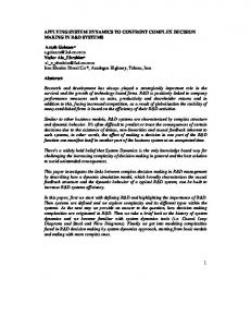
kind of analysis can be applied to model requirement volatility, error detection rates, defect correction rates, and other process and product characteristics; • Dynamic models: adoption of dynamic project models that allow scenario analysis, sensitivity analysis, and simulation. These mechanisms are applied to evaluate the impact of actions, decisions and risk occurrences along the development effort. The models serve as a project “micro-world”, where scenarios can be applied, contention and contingency plans can be developed, as well as tested and evaluated. Scenario based project management paradigm is centered on two artifacts: the project model and scenario models. The project model defines the project’s expected behavior, while scenario models describe alternative routes that the project may follow, due to unexpected events.
SCENARIOS
PROJECT MODEL
Figure 1 – Project model and scenario models
Scenarios hold the representation of management actions, theories, policies, and procedures, which can be enacted upon a software project. Finally, scenarios describe management strategies that can also be applied to a software project. These scenario categories are discussed in section 4. Scenarios can be plugged to the project model, modifying it to represent their consequences and respective expected behavior deviation. The project model describes the scenario integration interface. Both project and scenario models are formal software development models. A formal model describes the relationships among real world elements through mathematical or logical postulations. A software development model formalizes and integrates the laws and procedures that govern software development through a set of mathematical or logical formulations. Such models are used to fulfill several objectives: • Simulate decisions: decisions taken in software development projects can rarely be tested before applied (Abdel-Hamid and Madnick, 1991). Formal models can be used as a project “micro-world”, allowing the simulation of development process scenarios and the analysis of the project behavior based on specific decisions, according to the laws expressed by the model; • Formalize the knowledge about management relationships: the software engineering literature is very rich in defining the relationships among the elements that compose the software development process. However, these relationships are, in general, studied in isolation. An integrated software process model allows the formalization of the interactions among the project elements. These elements, when integrated, may show a distinct behavior than when they are analyzed in isolation; • Transfer knowledge about process relationships to inexperienced project managers: the high cost of testing project management decisions, due to the high cost of failing, brings difficulties to project managers training. A model that formalizes the relationships among development project elements, providing facilities for scenario and management decision simulation, can be used as a learning tool. Some experiences have shown that such tool promotes inexperienced project manager's knowledge enhancement, by allowing the
formulation and testing of management hypotheses (Maier and Strohhecker, 1996). Also, experienced project managers can document their knowledge in a standard form, sharing their knowledge with the trainees; • Provide operational project management: project models help to track project evolution, to identify, evaluate and monitor risks, through scenario analysis and simulation. Simulation is the technique that allows model behavior evaluation. Models are represented using system dynamics constructors. The integration of scenario models to the project model may reveal changes in the project behavior. Simulating a project model with and without a specific scenario demonstrates the potential impact of the scenario occurrence in the project behavior. The project model is called a concrete model, in the sense that it can be directly simulated, without any further integration to any other model. Scenario models, which can only be simulated when integrated to a project model, are called abstract models. 3 The Project Model In a commemorative paper for the 35th anniversary of system dynamics techniques, Forrester (1991) stated that, “… future training in enterprise design will include study of a library of generic management situations combining descriptive case studies with dynamic computer models …”. Although Forrester was highlighting a vision about training, we believe that the reuse of well-understood and generic management situation models have wider applicability within enterprise design. In mid-1980’s, Abdel-Hamid and Madnick (1991) developed a system dynamics software project model, which formalizes the effects of management policies and actions taken during a software development project. The model is divided into four major sections, covering human resource management, software production, project planning, and control. Their work has raised the attention to software dynamic behavior modeling and simulation, being followed by several other software project models (Lin and Levary, 1989) (Lin et al, 1997). Scenario based software project management explores the issue of building and integrating reusable scenario models within the software development domain. An independent software project model based on a modified version of Abdel-Hamid and Madnick’s model is being built. The project model describes the known facts about the project. Scenario models describe theories, management policies and procedures, reusable from an organization’s knowledge base or built for a particular project. The following paragraphs describe some of the extensions made to the original AbdelHamid and Madnick’s model to support scenario based project management paradigm: • Extendibility: models must be extensible, allowing the specialization of their parameters and the relations among their variables. It was solved by providing abstract models that can be reused and specialized for particular projects, capturing specific project characteristics; • Variable level integration: the model must integrate several variables referring to a software development effort, allowing project behavior evaluation after a change in a single variable. Integration promotes change effect propagation through variable relationships. So, a small change in a single variable may reflect in another subsystem or promote several orders of magnitude higher change in a model behavior, due to nonlinear variable level relationships and feedback loops; • Model level integration: models must clearly define their interfaces, so that a large model can be developed from the connection of smaller models. The same principle is used to
integrate scenario models to the project model, which is described in section 4 and exemplified in section 5; • Readability: the laws expressed by the model must be easily readable from that model. This feature promotes learning from the model, enhancing its extension and training capabilities. Large models must be decomposable into minor and less complex models, handling a much lower number of variables that can be studied in isolation. This characteristic also improves model understandability, extension and specialization; • Uncertainty representation: model parameters must express the inherent uncertainties of their values. Staff productivity, the number of activities and the time needed to perform a activity must not be expressed as a strictly defined number, but as probability mass functions (Vose, 1996) to express their uncertainty. Although we acknowledge other uncertainty representation mechanisms, probability distributions were selected due to their wide application in other areas of project management (Grey, 1995) (Wiest and Levy, 1977); • Uniform treatment: the original Abdel-Hamid and Madnick’s model treats uniformly all project elements of the same class. For instance, all experienced developers are supposed to have the same productivity, developers are assumed to be in the same exhaustion level, activities are supposed to take the same time to develop, and so on. We assume that this model simplification is due to system dynamics inherent incapability to describe element attributes. However, we believe that, if such a model is to be used for operational management, that is, tracking the software project from the start and projecting its behavior as new information about the project is available, the model must capture the differences among its developers, activities, and artifacts; • Representation level: the original Abdel-Hamid and Madnick’s model is composed of hundreds of system dynamics equations. These low abstraction level equations are very hard to understand and adapt. This representation level makes modeling a new software project a difficult task, since the modeler must carefully examine each equation for its validity in the new development effort. Scenario based project management defines a high level software project representation, based on descriptive process models, which can be translated to a system dynamics model. The later can be used for simulations, scenario and sensitivity analysis, while the first is used to describe a new software project without having to handle directly with flows and rates. • Separation of concerns: the elements that compose a software project model can be classified into two categories: facts and policies. Facts represent information about real world elements, such as developers, activities, artifacts, and life-cycle phases, and their relationships. Policies are theories, management actions and procedures, which change the real world elements’ behavior. Most of the models do not have a clear definition regarding the borderline between facts from policies. Policies are embedded within facts, their behavior and structure being distributed along hundreds of equations. The proposed project model attempts to separate facts from policies, modeling facts and regarding policies to scenarios that can be integrated to this model. This separation yields several benefits, such as less complex and more readable models, and general reusable policies that can be applied to a wider range of models. To describe the project model several descriptive process models found in the software engineering literature were analyzed to extract a simplified model that conveys most models’ common elements. Moreover, some adaptations were also made to this simplified model, aiming to highlight dynamic aspects of software development projects. Section 6.1 presents a
comparison between the proposed project model and previously published descriptive process models. The project model high-level representation is based on a software project four vertices spatial figure (Figure 2), a geometric analogy that highlights the model’s four major features: its activities, developers, artifacts, and resources. Activities are the central vertex, representing work packages that must be accomplished to conclude the project. Developers represent people working in a project. They accomplish activities using resources. Resources represent physical or logical elements that are used throughout project development, such as computers, software packages, and reusable components, among others. Activities create or evolve software artifacts, eventually using other artifacts as income. A software project is divided into several activities, which can be hierarchically decomposed into finer grained activities. Within a predefined hierarchical level, activities form a directed acyclic graph (DAG), whose edges represent activity dependency relationships. There are two kinds of activity dependencies. An AND dependency is a directed relationship, in such way that the target activity can only be initiated when the source activity is concluded. An OR dependency is also a directed relationship, such that the target activities are alternative activity execution paths that the project may follow. Artifacts
Activities Developers
Resources
Figure 2 – The software project spatial representation
Consider an activity graph, such as Figure 3. This activity graph is composed of nine activities. Most of the activities are connected by AND dependencies, represented by simple arrows. However, activity 3 has OR dependencies to activities 5 and 6, represented by arrows connected by an arc. This relationship indicates that, after executing activity 3, the project manager might choose between activities 5 and 6, both offering the basis for executing activity 8. The activity graph must be interpreted so that activities 1, 2, 3, 4, 7, 8 and 9 must be accomplished to conclude the whole graph, together with activity 5 or 6. 4 2
7
1
9 5 3
8 6
Figure 3 – Activity graph example, with AND / OR dependencies
Project managers select specific activities as project milestones. These milestones are useful to capture developer’s behavior when struggling to attend to a predefined schedule. As specified by the Abdel-Hamid and Madnick’s model (Abdel-Hamid and Madnick, 1991), developers tend to work harder when perceiving to be behind schedule. This overwork cannot stand forever, since developers have a limited capacity to work more hours a day for a long period. An exhaustion level represents this limit. Once a developer reaches a predefined exhaustion limit, he/she stops overworking for a period of time. At normal work rate, the developer’s exhaustion level is smoothly depleted, until the developer is fully recovered from
the overwork period. The original Abdel-Hamid and Madnick’s model considers a single milestone, project conclusion, driving schedule dynamics. The proposed project model allows defining several milestones, distributed throughout the development life cycle, and promoting minor schedule adjustments and overwork along the whole development time. Activity duration is expressed as a beta-PERT probability distribution function (Vose, 1996). This statistical distribution captures the project manager uncertainty about the necessary time to conclude each activity. The manager defines the beta-PERT distribution parameters, that is, the minimum and maximum estimated time for activity conclusion, instead of a single strict value for activity duration. Monte Carlo simulations (Vose, 1996) allow uncertainties propagation throughout the model, determining model results as distribution functions. For instance, since activity duration is not strictly defined, project conclusion date cannot be precisely calculated as a strict number. Instead, its probability distribution function is estimated through simulation, based on the stochastic activity duration. Along its development effort a software project passes through several life cycle phases. Every life cycle phase comprises a set of roles that developers can assume while working in that phase, and a number of technologies that can be applied during that work. Every project activity is associated to a life cycle phase, determining the applied technology and the developers who fulfill the necessary roles. The project model is also related to an application domain, where the application under development resides. The domain is used to capture relevant information that influences the project dynamics, such as staff domain expertise. The project model allows project status tracking. As new information is available about the status of project elements, it can be readily inserted into the project model, adjusting its expected behavior to its actual state. This project tracking support allows a project manager to update project status information throughout the development cycle. Once status information is inserted into the project model, a new system dynamics model can be generated from its high level representation. Since the new model accounts for recently available status information, scenarios and sensitivity analysis can be performed upon the project, allowing the project manager to adjust expectations of project behavior. The connection between activities and developers represents the developers assigned to execute an activity. Such relationship considers the developers experience in three distinct dimensions: the developer role, the technology used in the activity, and the problem domain. We assume that a software organization can describe their personnel experience in several application domains, executing each specific role and applying each specific technology used by the organization. Staff experience directly influences their productivity and error generation rates during software development. The connection between activities and artifacts presents activity influence upon software artifacts evolution along the project. Activities create, reuse or evolve software artifacts. They may use some previous developed artifacts as income to create new artifacts. This evolution may produce errors and require changes to previous developed artifacts. Each software artifact contains error and change evolution processes. To handle the inherited uncertainties of these processes, their attributes are stochastically described. Error generation dynamics are captured by the relationships among activities, developers, and artifacts. Developer’s expertise in the domain, in the applied technologies and in the roles assumed during project development impact error generation rates over the artifacts manipulated by an activity. Errors are also propagated among software artifacts, when a new artifact is built using erroneous artifacts as income. Finally, the connection between activities and resources demonstrates the use of resources by the activities. The separation of developers from resources in the project model highlights the distinction among human resources and software/hardware resources.
Developers and the roles they may take to accomplish some activity represent the former. Resources, as expressed within the project model, represent hardware aids, software tools and components, which are used to perform activities. Several descriptive project models describe both kinds of resources as a single class of elements (Humphrey and Kellner, 1989) (Christie, 1995). However, the proposed project model highlights human resources due to their relevance to project dynamics, imposed by different capabilities in software development domains, technologies, and in playing some roles. 4 Scenario Models Scenarios represent events, policies, procedures, actions, and strategies that cannot be considered part of a development project, but practices imposed or applied to the project and exceptional situations that the manager might encounter during project development. Scenario based project management paradigm states that the project manager must plan the project separately from its potential scenarios, using simulation to test scenario combination impact over project behavior. Scenarios can be classified into four major categories: • Potential events: these scenarios describe uncertainty events that can affect a software development project. These events may change the project original behavior, affecting project attributes, such as conclusion date, total development cost and quality level. Event scenarios are associated to specific project elements, such as technology, developer roles, artifacts, and application domain. For instance, the use of JAD techniques can present scenarios, such as higher amount of time dedicated to requirement analysis resulting in lower requirement volatility throughout the project. Projects in the financial application domain may be imposed to high requirement volatility and short development time frame; • Policies: these scenarios represent management policies and procedures that can be imposed to a project by organizational standards, high management and several other constraints. As it occurs with event scenarios, policy scenarios are associated to specific project elements. Examples of policy scenarios are delays to hire new employees, staff turnover, delays to buy necessary resources, and willingness to hire new employees. Policies represent tactical behavior patterns that can influence a large number of software projects subjected to a similar environment; • Theories: theory scenarios represent behavior patterns that the project manager believes may impact the project. These scenarios can represent proven theories (rare in the management science) and hypothetical theories resulting from common sense, expert advice or someone else experience. These scenarios represent behavior resulting from the interaction of several project elements. For instance, Abdel-Hamid and Madnick’ error propagation theory (Abdel-Hamid and Madnick, 1991) may be represented as a theory scenario. Theories represent tactical behavior patterns that can influence a large number of software projects, independent of its execution environment; • Strategies: these scenarios represent decisions that the manager may take for the project. They are useful to test the long and short-run impact promoted by the decision upon the project behavior. Examples of strategy scenarios are changing the developer responsible for an activity, allocating more resources to an activity, imposing milestones, creating a tiger team to handle a specific risk, and so on. Strategies represent project specific decisions, which are highly coupled to the elements that compose a specific software project.
Scenarios represent a reusable knowledge base to project managers. They allow formal documentation of assumptions and proven information about project elements and their relationship. This information can be reused to projects associated to these elements. During application development, when a project manager determines the current application domain, technologies to be applied during the development, developer roles, artifacts to be built, and so on, these elements associated scenarios help the manager to explore project uncertainties. Scenarios can also help training activities. Several combinations of management policies, theories and events, can be applied to a project model. Trainees can select management strategies, apply them to the project model and analyze their short and long run impact upon project behavior. We expect that the separation of project facts from scenarios, which are uncertain or represent particular assumptions, facilitate plug-&-play integration of several management strategies combinations. Scenario models are abstract models. They cannot be directly simulated. Instead, they must be integrated to a project model before simulation analysis. This integration occurs through an integration interface, represented by project model variables that scenarios can consult or act upon. Scenarios can consult whatever project model variable they desire. Although, project model variables are ultimately translated to system dynamics constructors, and rates and flows are described by simple equations that cannot be changed after model generation, scenario action over a project model is limited to stock variables. Scenario models can define rates that affect project model stocks. Scenario models also use other rates, processes or stocks to describe their internal logic, but scenario impact over the project model can only be described through scenario rates affecting project model stocks. 5 A Project Model and Sce nario Integration Example This section presents a simple example of designing a project model, a scenario model, integrating both models, and inferring their combined behavior through simulation. The project model used in the example explores the relationships among activities and developers, not accounting for consumed resources, artifact production and consumption, and their relationships to project activities. D1 D1 D2
Physical Devices Design (20)
Requirement Specification (30)
D2
D1 D2 Coding (40)
D1
Testing (20)
Logical Transmission Design (15) Figure 4 – Activities dependence graph for the telecommunication project example
Our example project aims to develop a telecommunication program to calculate the interference in radio diffusion channels. This program can be divided in two subsystems: the physical devices subsystem, which comprises the description of equipments, anthems, reflectors and radio stations, and the logical transmission subsystem, which is related to logical links, protocols and communication channels. We divided the development effort in five activities, as shown in figure 4. Each activity indicates its expected duration, expressed in man-days. The first activity, requirement elicitation, identifies and documents the functions that the system must perform. The following activities, executed in parallel, design the two subsystems’ implementation. Next, coding activity translates the design to a programming language, generating an executable
program. Finally, testing activity verifies whether the previously generated program has all the required functionality. Two developers, represented by the D1 and D2 roles accomplish the project. A single developer executes the design and testing activities, while both developers participate in the requirement elicitation and coding activities. Figure 4 also shows developers participation along project activities. The high level description of activities and participating roles presented in Figure 4 allows the generation of system dynamics equations that compose the project model. The use of a high level description facilitates project description understanding and evolution. Its conversion to system dynamics equations allows simulation, scenario integration and combined behavior analysis. Due to its extension, we do not present the generated system dynamics project model in this paper. However, two comments help understanding the scenario integration interface. Project elements are described by properties. In the example, their duration and the number of participating roles describe activities. Stocks in the project model represent these properties. They allow scenario models to consult and change project elements’ property values. Also, scenarios can analyze the change suffered by a property within each simulation iteration, that is, the net value of the entry and exit rates that connect a stock representing a project element property. Suppose that we are interested in analyzing the effects of communication overhead in activities executed by more than one developer. Since this overhead cannot be directly inferred from the project element properties, we need a scenario to describe its effects. Table 1 presents system dynamics equations that represent such scenario. TABLE COMMOVH 0, 0.015, 0.06, 0.135, 0.24, 0.375, 0.54; RATE (SOURCE, ) R VAR * LOOKUP (COMMOVH, , 0, 30);
Table 1 – Communication overhead scenario
The previous equations use a proprietary system dynamics simulator syntax. First, the TABLE command describes a set of values that can be accessed through the LOOKUP function. The communication overhead projection table was extracted from (Abdel-Hamid and Madnick, 1991). The LOOKUP function receives four parameters: a table, a search value, a value associated with the first table entry, and a value associated with the last table entry. It calculates a linear interpolation of the received search value within the table limits, returning the table value associated with it. The RATE command declares a flow between two stocks, shown within parentheses and separated by a colon. The first stock is the flow origin, which can also be an universal source, represented by the SOURCE keyword. The second stock is the flow target, which can also be an universal sink, represented by the SINK keyword. The flow name, R, is presented next to the stocks. Finally, the command shows the flow rate control equation, which uses the LOOKUP function to access the communication overhead table. Scenario models use extended system dynamics syntax. Commands inside brackets specify the value of project element properties in the current simulation iteration. For instance, bracket-bounded commands specify the duration and count of participating roles activity properties. Commands inside bracket preceded by the VAR keyword specify the change suffered by a project element property in the current simulation iteration. Although they access project element properties, scenario models do not indicate the concrete project elements to which they are related. In our example, the scenario model uses some activity properties. However, it does not indicate to which specific activity it applies.
This characteristic emphasizes the abstract nature of scenario models, which describe some behavior without being associated to concrete elements. Scenario model binding to project elements occurs during scenario and project model integration. Being a concrete model, the project model can be simulated without the scenario. The left-hand graph in Figure 5 shows project expected behavior without the scenario, presenting the CODE and TEST activities expected work to be done along development time. Meanwhile, as we are interested in analyzing the effects of communication overhead in the project, we must simulate the previous scenario impact to the project model expected behavior. Since the scenario model is an abstract model, it must be integrated to the project model before the simulation occurs. To accomplish this integration, the project manager selects the project elements to which each scenario is applicable. In the example, the project manager selects the activities to which the communication overhead scenario applies, that is, the requirement specification and coding activities. The integration process changes the bracketed commands in the scenario equations to the specific stocks and rates that represent, respectively, the activities properties and their instantaneous change in the current simulation iteration. Referring to specific stocks and rates, the conjunct scenario and project model is transformed into a concrete model and simulated. The right hand graph in Figure 5 presents the simulation results.
CODE
TEST
CODE
79
76
73
70
67
64
61
58
55
52
49
46
43
40
37
34
79
76
73
70
67
64
61
58
0 55
0 52
10 49
10 46
20
43
30
20
40
30
37
40
34
40
31
50
28
50
31
Project Behavior With Scenario Model
28
Project Behavior Without Scenario Model
TEST
Figure 5 – Project behavior simulation with and without the scenario model
From the graphs presented in Figure 5, we can observe that communication overhead introduces a delay to the proposed project, affecting the requirement specification and coding activities expected behavior. Without the scenario model, the project is executed in 76 days, while the scenario model delays its conclusion by 3 days. The proposed technique allows a project manager to formulate a theory, describe it as a scenario model, and test its impact upon a project. The scenario model can be stored in a reusable knowledge base, being available to other software project managers to apply in their projects. 6 Related Works In this section, we compare Scenario Based Project Management approach with related approaches presented in the literature. First, section 6.1 compares the project model with models proposed for operational project management, such as CPM, and Petri net-based models. Next, section 6.2 compares the process model to some system dynamics project models developed after Abdel-Hamid and Madnick’s model.
6.1 A Comparison with Mod els for Operational Project Management This section compares the proposed project model to operational project management models presented in the software engineering literature. This comparison aims to highlight the project model contributions to planning and monitoring software development projects. The Work Breakdown Structure (WBS) is a graphical portrayal of a project, detailing it in a level-by-level fashion down to the degree of detail needed for effective planning and control (Liu and Horowitz, 1989). Comparing the project model to WBS, we identify several advances in the former. First, WBS does not represent the developers engaged neither the resources consumed during project development. Next, WBS has no explicit representation for software artifacts evolution, not allowing a project manager to infer the state of artifacts constructed on its basis. Artifact evolution, captured by error and change evolution processes, is a major focus in the project model. Moreover, WBS does not represent activity dynamic properties, such as activities that are executed in parallel or dependencies among activities. Finally, WBS does not offer mechanisms to track project evolution, such as representing the concluded activities and project milestones. Again, this is a major concern of the project model, so that the expectations about project behavior can be quickly updated as new information arrives from the development fields. The Critical Path Method (CPM) model (Wiest and Levy, 1977) emphasizes the precedence relationships among activities. These relationships form a directed acyclic graph, from where the earliest start date and the latest completion date of each activity can be inferred, based on strictly defined activity duration. Comparing the project model to CPM, we identify several differences. First, CPM cannot handle OR dependencies between activities, representing only predecessor relationships, which are equivalent to the project model AND dependency. Next, CPM does not represent developers engaged or resources consumed by each activity. Moreover, CPM has no explicit mechanisms to track project or artifact evolution. Finally, CPM assumes that activity duration can be precisely defined as a strict number. The proposed project model assumes that this duration is uncertain, representing it as a beta-PERT probability distribution function. This problem does not remain when we compare the project model to the PERT model (Wiest and Levy, 1977), which is an extension of the CPM model. As the project model, PERT uses a beta-PERT probability distribution function to describe activity duration, instead of a precise number. However, the PERT model also shares the other problems that do apply to the CPM model. Lee and Murata (1994) present a stochastic Petri net-based model for software projects. A Petri net is an abstract model for describing and analyzing concurrent systems. It is composed of places, where tokens reside, and transitions, represented by directed arrows that link place pairs. A transition can be fired when tokens are available in their origin places. In Lee and Murata’s model, the Petri net’s places represent the activities that compose a software project, while its transitions represent activity dependencies. The Petri net is able to describe AND and OR dependencies among activities, through different transition combinations. The cost and time to conclude each activity, both described by a beta-PERT probability distribution function, are annotated in the net’s places. Comparing Lee and Murata’s model to the proposed project model, we observe some major differences. First, Lee and Murata’s model considers only two attributes of a single software project element, that is, activity duration and cost. The project model assumes that these attributes can be affected by several other factors, such as developer expertise, resource allocation, and so on. Next, Lee and Murata’s model does not explicitly represent developers and resources related to an activity. Finally, Lee and Murata’s model does not capture the dynamic aspects of artifact evolution, such as error and change dynamics. Liu and Horowitz (1989) present a model, named DesignNet, to describe the elements involved in a software project and their interactions. DesignNet is based on AND/OR graphs
and on Petri nets. An AND/OR graph is a hierarchical decomposition structure, where an element is described as the union of several lower level elements or a selected element from a lower level set. A graph AND/OR decomposes the project work breakdown structure in DesignNet. A Petri net links WBS work packages, mapping prerequisite relationships among elements through its transitions. The Petri net firing sequence represents the project execution process. A modified firing process creates new tokens in the target places, not removing the tokens from the original places. During project execution, the tokens left in the Petri net places record project execution history. There are some issues considered in the project model that are not handled by DesignNet. First, DesignNet does not clearly define its element attributes, such as developer expertise, artifact size, and so on. Next, DesignNet does not explicitly handle uncertainties about its element attributes. Finally, DesignNet does not capture the dynamic aspects of artifact evolution, such as error generation and propagation. 6.2 A Comparison with Syst em Dynamics Models Since the publication of their work, several authors have proposed enhancements to Abdel-Hamid and Madnick’s software project model. This section compares the proposed project model to these system dynamics models. This comparison aims to highlight how the proposed project model can handle newly proposed software management policies and procedures. Lin and Levary (1989) had developed a system dynamics model, named SLICS, which models some innovative aspects of software development efforts. First, multiple milestones are taken throughout the project, forcing schedule dynamics to happen not only at the end of the project, but throughout it’s the whole software life cycle. The project model captures multiple milestones, allowing the manager to define the activities which completion is sought as a milestone. Next, SLICS supports information updating throughout the project, allowing its expected behavior to change over time. This feature is also explored in the project model, allowing the simulation of project behavior and scenario analysis, as new information is available. Finally, two kinds of training models are considered in SLICS: in-house and out-ofjob. In-house training considers that external mentoring is hired to accompany the organization staff along a period of time. Out-of-job training assumes that the developer team stops its usual work and goes to training sessions, outside its working environment. The project model can define these two training approaches as alternative scenario models, allowing these scenarios to be reused by several projects. Lin, Abdel-Hamid and Sherif (1997) had developed a new system dynamics model, named SPES, which inherits and enhances management policies implemented in the original Abdel-Hamid and Madnick’s model. First, activities are divided into several life cycle phases. Error propagation dynamics consider error propagation downstream the life cycle. In the project model, activities are organized in graphs and are related to life cycle phases. Developers’ expertise with the applied technology, assumed roles and application domains influence error generation and propagation across the software artifacts manipulated by the activities. Next, SPES highlights that several model parameters may depend on the application domain. But, it does not present a technique to support information extraction for a domain. The project model explicitly considers that developers’ expertise over an application domain influences the project behavior. Moreover, SPES classifies developers using two different attributes: origin and experience level. According to the origin attribute, a developer can be in-house or external. According to the experience level, a developer can be experienced or inexperienced. The developer classification affects his/her productivity. The project model considers each developer profile in much more detail, characterizing their productivity and error generation rates due to their expertise in the roles played, applied technology and application domain. Finally, SPES allows development activities to be
eliminated due to resource, budget or schedule depletion. In the project model, the project manager can add or remove activities at the high level representation, resulting in different project behavior. Generically, two other features differentiate the project model from other system dynamics model. The first one is the high-level project model representation, which allows a more suitable representation of the project to its manager than system dynamics equations. The second feature is uncertainty representation, which allows the project manager to state the value of model parameters as probability distributions, instead of crisp numbers. 7 On Going Work This paper described a software project management paradigm, which is based on system dynamics models. Separate models represent known facts about the software project and exceptional events, management policies, procedures, and theories that can affect the project. The main contributions of this paper are showing how to use dynamic models to evaluate the impact of software project’s risks and their resolution strategies, the description of a high level project model that can be translated to system dynamics equations, and its integration to separate scenario models. We have also presented a small example of how scenario based project management paradigm can be used to simulate project behaviors with and without scenario models. The next steps will define more complex models, applying them to real operational project management situations. Besides, some experiments have been planned aiming at empirically validating some of the ideas discussed in this paper, whose results will be part of future papers. Acknowledgements The authors would like to thank CNPq and CAPES, for their financial investment in this work. References Abdel-Hamid, T., Madnick, S.E. (1991) Software Project Dynamics: an Integrated Approach, Prentice-Hall Software Series, Englewood Cliffs, New Jersey Augustine, N.R. (1982) Augustine’s Laws, American Institute Of Aeronautics and Astronautics, New York Boehm, B.W., Ross, R. (1989) “Theory W Software Project Management: Principles and Examples”, IEEE Transactions on Software Engineering, Vol. 15, No. 7, (July) Brown, N. (1996) Industrial-Strength Management Strategies, IEEE Software, Vol. 13, No. 4, pp 94–103 (July) Charette, R.N. (1996) Large-scale Project Management is Risk Management, IEEE Software, Vol. 13, No. 4, pp 110-117, (July) Christie, A. (1995) Software Process Automation: The Technology and Its Adoption, Springer-Verlag Publishing, Berlin Forrester, J.W. (1991) System Dynamics and the Lessons of 35 Years, Technical Report D4224-4, Sloan School of Management, Massachusetts Institute of Technology Genuchten, M. (1991) Why Is Software Late ? An Empirical Study of the Reasons for Delay in Software Development, IEEE Transactions on Software Engineering,Vol. 17, No 6, pp 582 – 590 (June) Gilb, T. (1988) Principles of Software Engineering Management, Addison-Wesley Publishing Company, Reading, Massachusets
Grey, S. (1995) Practical Risk Assessment for Project Management, Wiley Series in Software Engineering Practice, John Wiley & Sons Inc, New York Humphrey, W.S., Singpurwalla, N.D. (1991) Predicting (Individual) Software Productivity, IEEE Transactions on Software Engineering, Vol. 17, No. 2 (February) Humphrey, W.S., Kellner, M.I. (1989) Software Process Modeling: Principles of Entity Process Models, Technical Report CMU/SEI-89-TR-2, ESD-89-TR-2, Pittsburgh, PA Lee, G., Murata, T. (1994) A β-Distributed Stochastic Petri Net Model for Software Development Time/Cost Management, Journal of Systems and Software, Vol. 26, pp. 149-165 Lin, C.Y., Levary, R.R. (1989) Computer-Aided Software Development Process Design, IEEE Transactions on Software Engineering, Vol. 15, No. 9, pp 1025-1037 (September) Lin, C.Y., Abdel-Hamid, T., Sherif, J.S., (1997) Software-Engineering Process Simulation Model (SEPS), Journal of Systems and Software, Vol. 37, pp. 263-277 Liu, L., Horowitz, E. (1989) A Formal Model for Software Project Management, IEEE Transactions on Software Engineering, Vol. 15, No. 10, pp. 1280-1293 (October) Maier, F.H., Strohhecker, J. (1996) Do Management Flight Simulators Really Enhance Decision Effectiveness ?, IN: The Proceedings of the 1996 International System Dynamics Conference, Cambridge, Massachusets Neumann, P.G. (1995) Computer Related Risks, Addison-Wesley Publishing Company, Reading, Massachusets Pressman, R. (1992) Software Engineering: A Practitioner’s Approach, Third Edition, McGraw-Hill International Editions, London Royce, W. (1998) Software Project Management: A Unified Framework, Addison-Wesley Publishing Company, Reading, Massachusets Vose, D. (1996) Quantitative Risk Analysis: A Guide to Monte Carlo Simulation Modeling, John Wiley & Sons, Inc, New York Wiest, J., Levy, F. (1977) A Management Guide to PERT/CPM, Prentice-Hall Editions, Englewood Cliffs, New Jersey