Microelectronic Engineering 59 (2001) 173–181 www.elsevier.com / locate / mee
Architecture of non volatile memory with multi-bit cells G. Campardo*, R. Micheloni STMicroelectronics, Memory Product Group, Flash Memory Division, Agrate Brianza ( MI), Italy Abstract The typical characteristic of flash memory technology, its flexibility, is seen as the main factor that explains the strong evolution of its demand, continuously generating new applications with the typical pervasiveness of the innovative semiconductor products. But the flexibility also determines the peculiar position of this product in the market. Flash memories are not a dedicated product, but they can, according to the environment, appear sometimes either as a standard part or as an application-specific circuit. For all applications, however, Flash memories always play a strategic role. Matrix architecture is one the most complex item in a memory chip design. Dimensions must be reduced to the minimum and space optimisation must be maximized. 2001 Elsevier Science B.V. All rights reserved. Keywords: NOR flash memory; Matrix organization; Multilevel cell
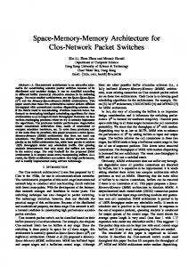
1. Flash memory operations The first three figures present a schematic summary of the principal operations done by a Flash memory device [1]. Program by channel hot electrons (CHEs), Fig. 1, is obtained by biasing the gate of the selected cell to Vpg (|10 V) and its drain to Vd (|4.5 V) in order to inject electrons into the floating gate. Program operations are developed internally using a finite state machine (FSM) that is connected with the external world by means of a command user interface (CUI). Verify operation is performed by the internal sense amplifier using a verify reference current. In order to be verified as programmed, the single cell must sink less current than the verify reference. Read is performed by means of a current-to-voltage conversion, after setting the cell current at a predefined gate voltage. Special care must be taken for the read voltage to avoid stress phenomena, Fig. 2. Electrical erase, Fig. 3, is performed on a sector by applying a negative gate voltage Vng (| 28 V), leaving the drain floating and biasing source at positive voltage Vps (|8 V), to have the electric field high enough for the Fowler–Nordheim (FN) tunnel. Also, in this case, like for the program, all the operations are done by the internal machine, FSM. Verify is performed after every erase pulse until reaching erased condition. * Corresponding author. E-mail address:
[email protected] (G. Campardo). 0167-9317 / 01 / $ – see front matter PII: S0167-9317( 01 )00618-9
2001 Elsevier Science B.V. All rights reserved.
174
G. Campardo, R. Micheloni / Microelectronic Engineering 59 (2001) 173 – 181
Fig. 1. Channel hot electrons (CHEs) write operation. The addressed cell has gate at Vpg |10 V and drain at Vd |4.5 V.
2. Flash memory organization The design of the Flash memory array is more difficult if compared to the design of an EPROM. For the EPROM the matrix structure is devised focusing on the access time which puts the constrain on the row and column length. This justifies splitting the matrix into different arrays with shorter rows and columns, by multiplying row and column decoders. During the architecture design of a matrix it is important to consider the impact of the electrical stresses related to the row and column length.
Fig. 2. Read architecture.
G. Campardo, R. Micheloni / Microelectronic Engineering 59 (2001) 173 – 181
175
Fig. 3. Fowler–Nordheim electrical erase. Cells of the same sector are erased with the gate at Vng 5 28 V, source at Vps 5 18 V and drain floating.
Typically row length is either 1024 or 2048 cells and the same applies to a column. Simple address decoding requires row and column size to be a power of 2. Fig. 4 shows some typical memory organizations made up by some submatrices. Row length is strongly related to the access time through
Fig. 4. Matrix and decoder organizations from 64 Kbit to 1 Mbit: (a) single array; (b) two arrays; (c) four arrays with doubled column decoders and a multiplexer to select the output data.
176
G. Campardo, R. Micheloni / Microelectronic Engineering 59 (2001) 173 – 181
the RC delay that depends on the process. The decrease of the poly resistance, thanks to the introduction of the silicide, is one of the factors that allow an increase in the row length, thus saving space without increasing the RC. The most evident difference between EPROM and Flash is the electrical erase: in the EPROM, it is performed on the whole matrix by UV radiation, while in the Flash it involves a set of bytes grouped into a sector. The first generation of Flash devices had only one sector and at the end of the electrical erasing the entire matrix was at the logical value 1. The evolution of the erase technique also changed the sector organization following the decrease of the supply voltage used by the customers in their application. The first Flash generation used an external voltage supply Vpp 512 V for the erase and program modes. The erase procedure applied to the cells 12 V at the source junction, ground on the gate and the drain was floating to obtain the high electric field across the tunnel oxide (between silicon and the floating gate) required for erase. This means that the common terminal during erase is the source: all the cells in the same sector must have the same source terminal. A simple sectorisation, for a NOR architecture, is shown in Fig. 5; matrix is divided in 2 submatrices, each of which contains 8 outputs; the sectors are distributed inside the single output. The parasitic bipolar transistor effect between two adjacent columns is reduced by interposing an empty column between two contiguous sectors. Each sector has its own ground connected by means of MOS transistors turned on during both read and program mode, while it is switched off in erase mode, so that a positive voltage can be on the cells’ source. Nodes discharge after erase pulse must be done carefully. In this case, at the end of the erase we will have the ground node charged at 12 V; the associated parasitic capacitance could be greater than 1 nF, and it is a function of the sector size. If this capacitor is discharged too quickly, we can have a coupling with the cell gate, dragging the junctions of the row
Fig. 5. Flash matrix with sectors organized by columns. The device has 8 equal outputs. Zoom shows the output 0 with different ground lines for each sector and empty columns between adjacent sectors to avoid parasitic bipolar turn on.
G. Campardo, R. Micheloni / Microelectronic Engineering 59 (2001) 173 – 181
177
Fig. 6. Different sector organization with the output replica for each sector.
decoder drivers below the ground voltage, thus turning on a latch up. Source node must initially be discharged slowly to reach a safety value and then it is possible increase the discharge speed. Another type of sectors architecture is shown in Fig. 6. The sectors are not distributed inside the output but they are concentrated and the output generation is obtained by a different column decoder organization to reach the sense amplifiers. Band to band current, IBBT , is always present for the high potential between source at 12 V and substrate node at ground. IBBT order of magnitude is 2–5 nA / cell, meaning 2–5 mA for 1 Mbit. Memory capacity increases but IBBT does not decrease, because ˚ for the reliability constrains and the electric we cannot decrease tunnel oxide thickness below 100 A field to erase remains the same. To achieve new market features like portability it is mandatory to obtain a reduction of supply voltage, in terms of both value and power consumption. Single voltage Flash generation had 5 V single Vcc supply; Vpp pin was removed and internal charge pumps were designed to generate all the voltages needed for the different operations [2–4]. All these items implied a different memory architecture design. Two points must be underlined: row length must be limited and source voltage, during erase, must decrease considering the limited current capability of the charge pumps. Using a local column decoder, single sectors are isolated one from the other, giving a zero stress outside the sector. Erase is obtained, on the single sector, with the negative voltage on the gate, the related source at positive voltage and the drain floating [5].
3. Matrix organized by sectors Customer requests always go in the direction of increased memory capacity and erase / write cycles number and decreased sector size. The solution is to divide memory using the hierarchical row and column decoders obtaining more sectors. The same idea can also be used for the source, n-well and p-well switches, considering the sector as the building block of the array instead of a single memory cell [6]. Now a 64-Mb Flash memory based on a 2-bit per cell approach will be described [7]. The device has been fabricated using 0.18-mm CMOS technology. The process architecture is characterized by shallow trench isolation, triple well, to better manage negative voltages, double poly, to form floating and control gates of the Flash memory cell, and three metal levels for effective routing. Silicide is used for the second poly level for minimum interconnect resistance. The Flash memory cell is the standard common ground NOR type [1], which is very well suited to multilevel (ML) storage [8,9]. The cell is formed by a poly stacked gate and a self-aligned source. The
178
G. Campardo, R. Micheloni / Microelectronic Engineering 59 (2001) 173 – 181
Fig. 7. Organization of 64 Mbit Flash memory.
memory array (Fig. 7) is divided into 64 identical sectors of 1 Mb (512 k physical cells). Each sector is structured as 512 local word-lines by 1024 local bit-lines plus some additional bit-lines for the error correction code (ECC) information and column redundancy. Sixteen additional small sectors are also provided for row redundancy, as described below. Each sector is built on an isolated p-well (ip-well), which is included in a separate n-well region. This allows independent substrate biasing for each sector, which is vital to guarantee zero stress outside the sector. A 2-level hierarchical organization is used for both row and column decoding: so, main (i.e. global) and local (i.e. sector) interconnections are provided in both the horizontal and the vertical direction. A total of 1024 main word-lines are driven by the main (or global) decoder, which is placed on one side of the memory array. Main word-lines are in metal2. Local decoding, which is located on both sides of each individual sector, using an interleaved approach, drives local word-lines, implemented in poly2. Each main word-line can be connected to 1 of 4 local word-lines of the selected sector through the respective local row decoder. The local row decoder is an optimised three-transistor design, which allows positive and negative voltages, as well as ground, to be passed to the local word. A similar approach is adopted for column decoding. The local bit-line decoding, which connects 1 out of 4 local metal1 bit-lines to the respective metal3 main bit-line, is also split into two parts, placed above and below the corresponding sector. In this case, the local decoder is made up of only one n-channel transistor, as non addressed bit-lines are left floating. Sensing is performed in parallel on 64 memory data cells. Main bit-line decoding selects 64 main bit-lines from the addressed sector and passes the current delivered by the addressed cells to 64 sense amplifiers. Main bit-lines corresponding to column redundancy and to ECC information are also selected in parallel with the array cells, and drive dedicated sense amplifiers. As 4 parity cells for each block of 32 data cells are required by the ECC, and one redundancy main bit-line is provided for each group of (6418) main data and parity bit-lines, the total count of sense amplifiers turns out to be 73. Column redundancy includes 4 main bit-lines for each vertical group of 8 sectors, i.e. one for each set of (6418) data and parity main bit-lines selected simultaneously. Spare bit-lines are embedded in the memory array, and are arranged in a data path identical to the normal one. To increase failure coverage, row redundancy techniques are also provided: these are exploited in the presence of bit-fails in more than one in the same set of (6418) main bit-lines. A total of 8 spare main word-lines are available for each vertical group of 8 sectors. Spare word-lines are organized in 16 small sectors (2 for each vertical group of sectors), placed in two
G. Campardo, R. Micheloni / Microelectronic Engineering 59 (2001) 173 – 181
179
rows, one just above and the other just below the main memory array. When row redundancy is used on a particular sector, the corresponding redundancy sector is logically associated with it, and all operations performed on the repaired are also carried out on its associated redundant sector. The redundant addresses are stored in an unerasable programmable read-only memory (UPROM) at wafer sort.
4. Sensing To detect the cell content, a parallel sensing approach was implemented [10]. The current Icell drawn by any addressed cell under predetermined gate and drain bias conditions, is simultaneously compared with three currents Iref1 , Iref2 , and Iref3 , provided by suitable reference cells (Fig. 8). The comparison result is then converted into a binary code. A complete sense amplifier includes three comparison stages, each performing current multiplication, current-to-voltage (I–V ) conversion, and final discrimination. In the presence of a limited read gate voltage VGR (|6 V, see below) and a low cell transconductance (|20 mA / V), array and reference cell currents are rather low, and small current differences must therefore be detected. All currents are thus amplified before being fed to the corresponding I–V converter. This function is achieved by simple current mirrors provided with a scaling factor larger than unit, which will be referred to as m and n for the array and the reference
Fig. 8. Parallel sensing approach and reference cells position.
180
G. Campardo, R. Micheloni / Microelectronic Engineering 59 (2001) 173 – 181
side, respectively. The value of VGR was set to 6 V as the best trade-off between design issues (providing sufficient spacing between adjacent programmed states) and reliability considerations (minimizing read disturbs) [11]. The highest reference level (VTR 3 ) was set substantially equal to the upper value of the third threshold voltage distribution. This approach provides some more room for allocating the two intermediate states (10 and 01), while still ensuring an adequate read overdrive voltage (VGR 2VTR 3 ) to the highest-threshold reference cell and, hence, a sufficient value for Iref3 . For safe detection of these cells, the current mirror factor in the third comparison channel was set different for the array and the reference side. Mirror factors m and n are instead equal for the two other channels, as the corresponding reference levels were placed midway between the adjacent distributions. To be specific, n was set to 2 for all comparison channels, while m was set to 2 for the first and the second channel, and to 3 for the third one.
5. Multilevel programming Four states must be accommodated with adequate spacing in the allowed threshold window. To this end, program-and-verify and staircase gate voltage programming techniques were adopted. Programming is carried out by applying a sequence of program pulses, each followed by a verify step. Programming is continued only for the cells that need further threshold shift. Moreover, for any programming pulse, the voltage applied to the gate of the addressed cells is increased by a constant amount DVGP , thus resulting in a staircase-shaped program gate voltage [12–14]. Indeed, after an initial transient, each programming step leads theoretically to a threshold voltage increase equal to DVGP . Using this technique in conjunction with the Program and Verify approach, leads to adequately narrow threshold distributions even though, in practice, the achievable distribution widths are larger than DVGP due to non-idealities such as verify circuit inaccuracies and voltage fluctuations. An additional advantage of the staircase programming method resides in its moderate drain current requirements, preventing excessively high overdrive voltages and leading to reduced drain current sinking. In our device, the staircase program voltage reaches a maximum of 9 V with a constant DVGP at each step. A resistive-string based digital-to-analog converter generates the staircase voltage. To achieve adequate program throughput, parallel programming was adopted, which is made possible by the moderate current required by a single memory cell. 16 words (256 bits) are loaded into a buffer together with the corresponding calculated ECC parity bits, and the entire writing procedure is then carried out under the control of an internal routine. Program throughput is 1B / 6 ms.
6. Erase Erase is achieved by applying a negative voltage (| 28 V) to all the local word-lines of the selected sector, and a positive voltage to its source / ip-well and n-well terminals (channel erasing is thus obtained). Source voltage is incremented at each step to achieve a more controlled threshold decrease and improve reliability [15]. Any erase operation is carried out following an erase-and-verify approach (obviously, only verify is carried out at the bit level). A typical problem in NOR-type memories is to avoid the presence of depleted cells as bit-line leakage must be avoided. To this end,
G. Campardo, R. Micheloni / Microelectronic Engineering 59 (2001) 173 – 181
181
an algorithm is implemented which searches for depleted cells in the erased sector and, if necessary, performs a soft-programming routine to increase their threshold level. 7. Conclusion A survey on matrix architecture from EPROM to Flash approach has been presented. A 64 Mb 2b-cell CHE programmed NOR-type Flash memory has been described. Adequately narrow threshold distribution widths were obtained for each programmed state by using Program and Verify and staircase program voltage techniques. Reliable and fast cell reading is obtained with a parallel sensing technique. The use of an 0.18-mm STI CMOS process together with the ML storage approach, led to a chip size of 40 mm 2 . References [1] P. Pavan, R. Bez, P. Olivo, E. Zanoni, Flash memory cells — an overview, Proc. IEEE 85 (8) (1997) 1248–1271. [2] J. Dickson, On-chip high voltage generation in NMOS integrated circuits using an improved voltage multiplier technique, IEEE J. Solid-State Circuits 11 (3) (1976) 374–378. [3] T. Tanzawa, T. Tanaka, A dynamic analysis of the Dickson charge pump circuit, IEEE J. Solid-State Circuits 32 (8) (1997) 1231–1240. [4] J.-T. Wu, K.-L. Chang, MOS charge pumps for low-voltage operation, IEEE J. Solid-State Circuits 33 (1998) 592–597. [5] M. Dallabora et al., A 20 MB / s data rate 2.5 V Flash memory with current controlled field erasing for 1 M cycle endurance, in: IEEE International Solid-State Circuits Conference (ISSCC) Dig. Tech. Papers, San Francisco (California, USA), 1997, p. 396. [6] R. Micheloni et al., Hierarchical sector biasing organization for flash memories, in: IEEE International Workshop on Memory Technology, Design and Testing (MTDT 2000), San Jose, CA, 2000, pp. 29–33. [7] G. Campardo, et al., 40-mm 2 3-V-only 50-MHz 64-Mb 2-b / cell CHE NOR Flash memory, IEEE J. Solid-State Circuits 35 (11) (2000) 1655–1667. [8] B. Eitan et al., Multilevel Flash cells and their trade-offs, IEDM 1996 Tech. Dig. Dec. 1996, pp. 169–172. ` et al., Nonvolatile multilevel memories for digital applications, Proc. IEEE 86 (12) (1998) 2399–2421. [9] B. Ricco, [10] C. Bleiker, H. Melchior, A four-state EEPROM using floating-gate memory cells, IEEE J. Solid-State Circuits 22 (1987) 460–463. [11] O. Khouri, R. Micheloni, G. Torelli, Very fast recovery word-line voltage regulator for multilevel nonvolatile memories, in: Proc. Third IMACS / IEEE International Multiconference on Circuits, Systems, Communications and Computers (CSCC), Athens (Greece), June, 1999, 1999, pp. 3781–3784. [12] C. Calligaro, A. Manstretta, A. Modelli, G. Torelli, Technological and design constraints for multilevel flash memories, in: Proc. 3rd IEEE Int. Conf. Electronics, Circuits and Systems, Oct. 1996, 1996, pp. 1003–1008. [13] K.-D. Suh, B.-H. Suh, Y.-H. Lim, J.-K. Kim, Y.-J. Choi, Y.-N. Koh, S.-S. Lee, S.-C. Kwon, B.-S. Choi, J.-S. Yum, J.-H. Choi, J.-R. Kim, H.-K. Lim, A 3.3-V 32-Mb NAND flash memory with incremental step pulse programming scheme, IEEE J. Solid-State Circuits 31 (1995) 1149–1156. [14] Y.-J. Choi, K.-D. Suh, Y.-N. Koh, J.-W. Park, K.-J. Lee, Y.-J. Cho, B.-H. Suh, A high-speed programming scheme for multilevel NAND flash memory, in: Symp. VLSI Circuits Dig. Tech. Papers, June 1996, 1996, pp. 170–171. [15] K. Yoshikawa, S. Yamada, J. Miyamoto, T. Suzuki, M. Oshikiri, E. Obi, Y. Hiura, K. Yamada, Y. Ohshima, S. Atsumi, Comparison of current flash EEPROM erasing methods; stability and how to control, IEDM Tech. Dig. (1992) 595–598.