1132
IEEE TRANSACTIONS ON COMPUTER-AIDED DESIGN OF INTEGRATED CIRCUITS AND SYSTEMS, VOL. 21, NO. 10, OCTOBER 2002
Area Fill Synthesis for Uniform Layout Density Yu Chen, Andrew B. Kahng, Gabriel Robins, and Alexander Zelikovsky
Abstract-Chemical-mechanical polishing (CMP) and other manufacturing steps in very deep submicron very large scale integration have varying effects on device and interconnect features, depending on local characteristics of the layout. To improve manufacturability and performance predictability, the authors seek to make a layout uniform with respect to prescribed density criteria, by inserting "area fill" geometries into the layout. In this paper, they make the following contributions. First, the authors define the flat, hierarchical, and multiple-layer filling problems, along with a unified density model description. Secondly, for the flat filling problem, they summarize current linear programming approaches with two different objectives, i.e., the Min-Var and Min-Fill objectives. They then propose several new Monte Carlo-based filling methods with fast dynamic data structures. Thirdly, they give practical iterated methods for layout density control for CMP uniformity based on linear programming, Monte Carlo, and greedy algorithms. Fourthly, to address the large data volume and inherent lack of scalability of flat layout density control, the authors propose practical methods for hierarchical layout density control. These methods smoothly trade off runtime, solution quality, and output data volume. Finally, they extend the linear programming approaches and present new Monte Carlo-based methods for the multiple-layer filling problem. Comparisons with previous filling methods show the advantages of the new iterated Monte Carlo and iterated greedy methods for both flat and hierarchical layouts and for both density models (spatial density and effective density). The authors achieve near-optimal filling for flat layouts with respect to each of these objectives. Their experiments indicate that the hybrid hierarchical filling approach is efficient, scalable, accurate, and highly competitive with existing methods (e.g., linear programming-based techniques) for hierarchical layouts. Index Terms-Area fill, chemical-mechanical polishing, hierarchical layout, layout density control, layout planarization, Monte Carlo methods.
A
I. INTRODUCTION
S PREDICTED by the Semiconductor Industry AssociAation's Technology Roadmap [21], very large scale integration (VLSI) technology has entered deep submicron regimes, Manuscript received October 8, 2000: revised December 24, 2001. This work was supported in part by a Packard Foundation Fellowship, by the MARCO Gigascale Silicon Research Center, by the National Science Foundation under Young Investigator Award MIP-9457412, by the National Science Foundation under Grant CCR-9988331, Award MM@ 3018 of MRDA & CRDF, by the State of Georgia's Yamacraw intitiative, and by a grant from Cadence Design Systems, Inc. This paper was recommended by Associate Editor M. Pedram. Y. Chen is with the Department of Computer Science, University of California at Los Angeles, Los Angeles, CA 90095-1596 USA (e-mail:
[email protected]). A. B. Kahng is with the Departments of Computer Science and Engineering and Electrical and Computer Engineering, University of California at San Diego, La Jolla, CA 92093-0114 USA (e-mail:
[email protected]). G. Robins is with the Department of Computer Science, University of Virginia, Charlottesville, VA 22903-2442 USA (e-mail:
[email protected]). A. Zelikovsky is with the Department of Computer Science, Georgia State University, Atlanta, GA 30303 USA (e-mail:
[email protected]). Digital Object Identifier 10.1 109/TCAD.2002.802278.
where the manufacturing process increasingly constrains physical layout design and verification [16]. Many process layers, including diffusion and thin-ox, have associated density rules that are satisfied by postprocessing steps which add areafill geometries to the layout. Historically, only foundries or specialized technology computer-aided design (TCAD) tool companies performed the layout postprocessing necessary to achieve layout uniformity. Today, however, electronic computer-aided design (ECAD) tools for physical design and verification cannot remain oblivious to such postprocessing phases.
Literature on area fill has focused on chemical-mechanical polishing (CMP) of spin-on glass (SOG) interlayer dielectrics (ILD) [14], [18], [27]. Postpolish ILD thickness variation is kept within acceptable limits by controlling local feature density, relative to a process-specific "window size" (on the order of 1-3 mm), that depends on CMP pad material, slurry composition, and other factors [7].I
Application of area fill to device layers (diffusion, poly, thin-ox) is equally (or even more) critical. Isolated transistors are susceptible to contact overetch in reactive ion etch (RIE) process steps, which results in leakage. Chemical vapor deposition (CVD) steps are also subject to iso-dense variations. CVD and etch process variation are particularly troublesome with respect to today's lightly doped drain (LDD) device properties. The bottom-line performance effects of these process variations are well known, e.g., Garofalo et al. [8] document 10% variation in interline capacitance resulting from 5% variation in linewidth and 12% error in ring oscillator frequency solely from proximity effects. At the same time, it is also well known that the uniformity of feature density obtained via area fill can mitigate macroscopic process proximity effects such as contact etch variation in reactive ion etch, and nonuniformity of chemical vapor deposition. With respect to the potential negative effects of area fill insertion, certainly the fill geometries can affect interconnect capacitance, signal delay, and crosstalk. The exact change in interconnect capacitance depends mainly on the size of the fill geometries and proximity to interconnect lines. However, Grobman et al. have recently given detailed experimental data [10] pointing out that capacitance of dense lines is not significantly affected by floating fill geometries on neighboring layers, since this capacitance is mostly dominated by same-layer neighbor coupling. Furthermore, smaller fill geometries reduce crosstalk to distant neighbors and lead to a smaller increase in total capacitance. The conclusion from such analyses is that the first-order performance concern remains to 'We observe that the 1999 International Technology Roadmap for Semiconductors [22] added copper interconnect dishing to the fundamental roadmap parameters for Interconnect. (The 2000 ITRS also added copper interconnect thinning in CMP to the fundamental parameters.) Density-mediated process variation has therefore become a first-order concern for interconnects.
0278-0070/02$17.00 © 2002 IEEE
1133
CHEN et al.: AREA FILL SYNTHESIS FOR UNIFORM LAYOUT DENSITY
improve planarization and uniformity of geometry via area fill insertion. Finally, we note that current industry tools appear to be slow in handling detailed physical models of CMP, such as those addressed by our work. To the best of our knowledge, most current industrial tools such as Cadence Assura 2.0 perform fill insertion as part of physical verification, using rule-based methods. The underlying geometry engines are tuned to Boolean operations on layout layers and to local (e.g., width/spacing rule) checks. A typical use of such infrastructure is to simply insert area fill geometries to increase local density wherever there exist large enough slack areas. This is usually done with Boolean operations to find the slack areas and fill them with geometries of a prescribed density. The main problem with this method is that the spread between minimum and maximum densities is usually fairly large, and it is unclear how the fill insertion approach is related to known analytical models for the relationship between local density and ILD thickness. Comparisons with industry tools have not been possible, as no commercial tools of which we are aware offer hierarchical fill insertion capability, and the related methods of [25] are Motorola-internal and not publicly available [9].
A. Organization of the Paper
The remainder of our paper reviews the range of local density models and density control objectives, then proposes several new approaches to a flat and hierarchical density control for CMP. Section II defines the single-layer filling problem for both flat and hierarchical layouts. Both formulations are based on the practical industry standard fixed dissection density analysis regime [12]. Relevant objectives include the Min-Var and Min-Fill objectives. Though hierarchical filling can speed up verification of filled layout and decrease data volume, there is an obvious conflict between honoring the layout hierarchy and achieving high-quality filling results. The filling problem for multiple-layer layouts is then discussed, where the cumulative density effect is considered. Section III gives a unified description of existing models for density calculation for CMP. We review a standard model for oxide planarization via CMP and describe spatial local density and effective local density models. Section IV first reviews several linear programming (LP)-based approaches that determine the optimal fill amounts to be inserted into the layout, with respect to the Min-Var and Min-Fill objectives. Then, because LP approaches tend to require too much memory in practice, we propose new Monte Carlo-based approaches for flat filling, which are as accurate and yet faster than LP approaches. Section V analyzes the difficulties inherent in hierarchical filling, as well as the reasons why the LP approach is sometimes inapplicable. We then propose anew Monte Carlo filling approach and a hybrid hierarchical/flat filling approach which is scalable, efficient, and highly competitive with flat filling. Section VI discusses the extensions of LP and Monte Carlo approaches to a multiple layer model. Sections VII and VIII describe our implementation testbed and computational experience, and Section IX concludes with directions for future research.
II. THE
FILLING PROBLEM
Layout density control consists of two phases: density analysis andfill synthesis. Density analysis determines the area available for filling. Fill synthesis then computes the amount of fill feature area which should be added into each part of the layout in order to achieve uniformity, then generates the required fill geometries. In this paper, we address the main problem of the area fill synthesis phase. A. Flat Filling
Given a design rule-correct layout in an n x n layout region, along with a window size w < n, and upper (U) and lower (L) bounds on the feature density in any window, add areafill geometries to create afilled layout such that either: * (Min-Var Objective) the variationin window density (i.e., maximum window density minus minimum window density) is minimized while the window density does not exceed the given upper bound U; or * (Min-Fill Objective) the number of inserted fill geometries is minimized while the density of any window remains in the given range (L, UJ). The Min-Var objective, introduced in [12], captures the "manufacturing side" of fill synthesis, which seeks the most uniform density distribution possible. The Min-Fill objective, recently proposed in [25], models the "design side" in that it seeks to minimize the coupling capacitance and the uncertainty caused by filling. Algorithms for filling flat designs can be classified into two categories: linear-programming (LP)-based approaches [12], [25], and Monte Carlo-based methods [4], [5]. B. HierarchicalFilling
Hierarchy arises in both custom and semicustom design flows. In custom design, hierarchy is used mostly for streamlining the management and the decomposition of the design problem. In semicustom design, hierarchy is associated more with reuse of standard cells, whose layouts include device layers and local interconnect, or IP blocks. The key observation is that hierarchical designs become difficult to verify when flattened. Hence, hierarchical filling can enable simpler and faster verification of the filled layout, since verification can still follow the structure of the original hierarchy. Hierarchical filling can also decrease data volume for standard-cell designs. (In general, data volume is a big issue for area fill since a filling solution can consist of many millions of tiny geometries.) Thus, hierarchical fill generation is an emerging requirement for future commercial EDA tools [20]. Our present work investigates approaches and tradeoffs inherent in filling master cells rather than just individual instances. We consider hierarchical filling as a postprocessing step performed (on device layers) after placement. When router access to local interconnect (salicide) and Ml layer is strongly restricted, 2 then hierarchical filling may be performed after routing as well. Hierarchical filling entails obvious complex constraints. 2For example, Cadence and Avant! gridded routers are often restricted to welldefined pin availabilities at points of the routing grid.
1 134
IEEE TRANSACTIONS ON COMPUTER-AIDED DESIGN OF INTEGRATED CIRCUITS AND SYSTEMS, VOL. 21, NO. 10, OCTOBER 2002
Overlaps with features A
Overlaps between 2 instances of the same master cell/
/ \\
K
\N I
.11 A
I fA
Cell A
-.-r
Or
U
-
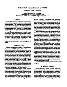
Overlaps between 2 instances of different master cells Eig.
1. The types of interactions or interferences with master cells.
* When area fill is inserted into a master cell, it must satisfy density constraints in all contexts for instantiations of the master. * There are many interactions or interferences at master cell boundaries and at distinct levels of the hierarchy (see Fig. 1). * Solution quality in terms of either the Min-Var or Min-Fill objective will be worse for hierarchical solutions than flat solutions, because the former are more constrained. * The number of constraints for LP-based hierarchical filling explodes combinatorially for the known LP-formulations, rendering unusable the linear programming techniques which have been successful for flat filling [12], [25]. The filling problem for hierarchical (standard-cell) layouts is similar to its counterpart for flat layouts, except that the hierarchical structure of master cells must be preserved, i.e., the same filling geometry is simultaneously added to all instances of the same master cell. Here, we assume that we can fill the slack (i.e., free) area of each master cell independently and uniformly. The HierarchicalFillingProblem: Solve the Filling Problem for a given standard-cell layout so that: * filling geometries are added only to master cells; * each cell of the filled layout is a filled version of the corresponding original master cell; * the increase in (hierarchical) layout data volume does not exceed a given threshold. C. Multiple-Layer Filling
In the layout with multiple layers, each layer except the bottom one cannot assume a perfectly flat starting surface. Thus, independently filling each layer optimally may not achieve an acceptable planarization for the top layers as layers are stacked during the manufacturing process. The Multiple-Layer Filling Problem: Solve the Filling Problem for a given multiple-layer layout so that either:
* (Min-Var Objective) the sum of variations in window density on each layer is minimized, or the variance of variations in window density on each layer is minimized; or * (Min-Fill Objective) the number of inserted fill geometries is minimized while the density of any window remains in the given range (Lk, Uk) for each layer k. III. A UNIFIED DESCRIPTION OF LAYOUT DENSITY MODELS FOR CMP
Several models for oxide planarization via CMP are reviewed in [18]. In particular, the accurate and well-accepted model of [23] is neither computationally expensive nor difficult to calibrate. In this model, the interlevel dielectric thickness z at location (x, y) is calculated as z =
Zo z
zo
Kit z -Kit + po(x, y)zl,
t < (pozi)/Ki
(1)
t > (pozi)lKi
where Ki is the blanket polish rate, zo is the height of oxide deposition, z1 is the height of existing features, t is the polish time, and po is the initial pattern density. The crucial element of the model is the determination of the effective initial pattern density p(x, y). In this section, we give a unified approach to two different definitions of pattern density studied in [12] and [25], respectively. This unification will allow us to exploit the same methods for layout density control for both pattern density definitions. The pattern density in (xI y) is a local property and therefore depends on spatial pattern density within some close range of the point (x, y). This local property may be captured by introducing (for a certain w) a w x w-window W centered at (x, y), and assuming that p(x, y) depends only on the pattern density distribution in W. To make the filling problem more tractable, a standard industry practice is to consider only a finite set of layout windows. Bounding the effective density in a fixed set of w x w windows
CHEN et al.: AREA FILL SYNTHESIS FOR UNIFORM LAYOUT DENSITY
with experimentally determined constants co, c1 , and c2 [25]. The discretized effective local pattern density p for a window Wij in the fixed-dissection regime (henceforth referred to as
W/r
w
y
I1135
effective window density) is \
ie
~i+r'-1 p(Wij) = E
j+ri1
k-i
E
area(Tk,)
i-i
f (k -(i + r/2), 1- (j + r/2))
(4)
where the arguments of the elliptical weighting function f are the x and y distances of the tile Tkl from the center of the window Wij. n
IV. FILL SYNTHESIS FOR FLAT LAYOUTS A. Linear ProgrammingApproaches 2
Eig. 2. The layout is partitioned using r (r = 4 in this example) distinct dissections (each with window size w x w) into (nr/w) x (nr/w) tiles. Each 2 dark-bordered w x w window consists of r tiles.
can incur substantial error, since other windows could still violate the density bounds. 3 A common industry practice is to enforce density bounds in 772 overlappingfixed dissections, where r determines the "phase shift" w/ r by which the dissections are offset from each other. In other words, to help control layout density in arbitrary windows, density bounds are enforced only for windows of the fixed r dissection (see Fig. 2), which partitions the n x n-layout into tiles Tij, then covers the layout by w x w-windows Wij, i, j = 1, ... , (nr/w) -1, such that each window WiVj consists of r72 tiles Tkl, k = i, . .. , i + r -1, I = j, . . ., j + r -1. Note that windows are "wrapped around" the layout, e.g., a window that overlaps with the upper edge of the layout also contains tiles on the bottom of the layout. This is not only convenient, but also reflects the fact that layout density at the edge of one die may affect the manufacturing of the die's neighbors on the wafer. We seek to understand how the effective density depends on the spatial pattern density distribution in a window. The simplest model for p(xI y) is the local area feature density, i.e., the window density is simply equal to the sum i+r-1 j+r-1
p(Wij)= E k=i
E
area(Tk)
(2)
l=j
where area(Tkl) denotes the original layout area of the tile Tk l. This model is due to [12], which solved the filling problem using linear programming. A more accurate model considers the deformation of the polishing pad during the CMP process [7], where the effective local density p(x, y) is calculated as the sum of weighted spatial pattern densities within the window, relative to an elliptical weighting function f (x, y) = co exp [c1 (x 2 ±+y2 )c2] 3
(3)
The analysis in [12] bounds the error that results from considering only a finite number of windows, versus considering all possible windows.
The LP approach seeks the optimum fill area pij to be inserted into each tile Tij. The fill area Pij cannot exceed slack(Tij), which is the area available for filling inside the tile Tij computed during density analysis. The first LP formulation for the Min-Var objective is [12] Maximize: M Subject to: >=
Pijiu
i j =U~...,W
i, j =O ... _-
Pij I- w2 and = 1, otherwise. Constraints (5) imply that we can only add features to, but cannot delete features from, any tile. The slack constraints (6) are computed for each tile: if a tile Tij is originally overfilled, then we set slack(T) = 0. The values of pij from the LP solution indicate the fill amount to be inserted into each tile Tij. The constraints (7) ensure that no window can have density more than U after filling, unless it was initially overfilled. Inequalities (8) imply that the auxiliary variable M is a lower bound on all window areas which include the original feature areas area(Tlt ) and the fill areas p t. The linear program seeks to maximize M, thus achieving the Min-Var objective. A followup work [25] proposed the Min-Fill objective, along with a Ranged Variation LP
Minimize:
E Pij
S j
i, j
Subject to:
1136
IEEE TRANSACTIONS ON COMPUTER-AIDED DESIGN OF INTEGRATED CIRCUITS AND SYSTEMS, VOL. 21, NO. 10, OCTOBER 2002
Monte-Carlo Filling Algorithm Input: n x n layout, fixed r-dissection into tiles Tij, i, j = ,... - 1, slack(T1 j) = slack of tile Tij, area(W 1 j) = area of w x w window Wij, unit fill = unit filling area, and U = upper bound on w x w window area. Output: filled layout 1. For each tile T initialize 2. insert in(T) = 0 3. priority(T) = f(Uslack(T),MaxWin(T)) 4. While the sum of tile priorities is positive Do 5. Select a random tile T according to priorities 6. insert-in(T) = insert-in(T) + 1; slack(T) = slack(T) - unit-fill 7. If slack(T) < unit-fill Then priority(T) = 0 8. Else priority(T) = priority(T)- unitfill 9. For each window W containing T Do 10. area(W) = area(W) + unit fill 11. For each tile T' E W Do 12. Update priority(T') according to area(W) 13. For each tile T Do 14. Randomly perturb sequence of grid positions: random(i) = 1,... ,slack(T)/unitjfill 15. For i = 1,...,insert in(T) Do 16. Insert a unit-fill geometry into the random(i)th grid position 17. Output the filled layout Fig. 3.
The Monte Carlo-based filling algorithm.
Pij>
ij
ni.
=0,...,-
pij < slack(Tij)
i,
j
L < po(i, j) < U
i,j
-1
0, ...
(9) 1
,-
1, ... ,
w
(10) -1
(1)
Here, p0 (i, j) is the effective density of tile Tij; L and UJ are the minimum and maximum tile effective densities, rcrespectively. We also note a variant LP for the Min-Var obje ctive: given a target window density M (instead of an upper bourid on window density), we minimize the variability budget E Minimize: E Subject to: (12)
0 1
k =1
where " - " is the fast Fourier transform (FFT) operator, P0(k) is the effective local density, Zk is the step height (i.e., the height of layer k from the first layer), dk is the local density (all for layer k), and f is the weighting function. In the discussion below, we will not explicitly address the multiple-layer model. However, our linear programming and Monte Carlo algorithms have straightforward extensions for simultaneously handling multiple layers. By mathematical induction on the layer number k and the linearity of Fourier transforms, (14) can be written as [25] k Pot(k) =
E
[(Zl/Zk)t k1+
(15)
X di]
1=1 Furthermore, in order to achieve effective density at location (i, j) on layer k, each term in the summation induces a multiple circular convolution in the physical domain
[IFFT (fao)
x d1 )] (i, j)
= [(f 0 f ... f) ®d1 ](i, j)
= E E [f(ii -i, jl -i) ii jl
E [z(iz
X' '(E
- iA
i
Ja -
1)
ice jct
(Xij' +X0Dl)]
(16)
Since a multiple convolution written as a series of summations is linear in term of pi, j, all LP formulations can be easily extended to multiple layers.
A. Linear ProgrammingApproachesfor Multiple-Layer Fill Wong et al. [25] extended the linear programming formulation to address multiple layers, with the objective of minimizing the sum of density variations over all layers K
Minimize: E
(H, -Lk)
k=1
Subject to: