shuffling technique introduced in the turbo-decoding field to ... include software and/or reconfigurable parts to achieve the required flexibility while achieving ...
DATE 2006
ASIP-Based Multiprocessor SoC Design for Simple and Double Binary Turbo Decoding Olivier Muller, Amer Baghdadi, Michel Jézéquel Electronics Department, ENST Bretagne, Technopôle Brest Iroise, 29238 Brest, France {olivier.muller, amer.baghdadi, michel.jezequel}@enst-bretagne.fr
Abstract This paper presents a new multiprocessor platform for high throughput turbo decoding. The proposed platform is based on a new configurable ASIP combined with an efficient memory and communication interconnect scheme. This Application-Specific Instruction-set Processor has an SIMD architecture with a specialized and extensible instruction-set and 5-stages pipeline control. The attached memories and communication interfaces enable the design of efficient multiprocessor architectures. These multiprocessor architectures benefit from the recent shuffling technique introduced in the turbo-decoding field to reduce communication latency. The major characteristics of the proposed platform are its flexibility and scalability which make it reusable for various standards and operating modes. Results obtained for double binary DVB-RCS turbo codes demonstrate a 100 Mbit/s throughput using 16-ASIP multiprocessor architecture.
1. Introduction Systems on chips in the field of digital communication are becoming more and more diversified and complex. In this field, performance requirements, like throughput and error rates, are becoming increasingly severe. To reduce the error rate with a lower signal-to-noise ratio (closer to the Shannon limit), turbo (iterative) processing algorithms have recently emerged [1][2]. These algorithms, which originally concerned channel coding, are currently being reused over the whole digital communication system, like for equalization, demodulation, synchronization, and MIMO. Furthermore, the severe time-to-market constraints and the continuously developing new standards and applications in this digital communication, make resorting to new design methodologies and the proposal of a flexible turbo communication platform inevitable. Flexibility could be achieved by the use of programmable/configurable processors rather than ASICs. Thus, embedded multiprocessor architectures integrating an adequate communication Network on Chip (NoC) will constitute an ultimate solution to preserve flexibility while achieving the required computation and throughput rates. Algorithm parallelization of turbo decoding has been widely investigated these last few years. Several implementations have also been proposed. Some of these
implementations succeeded in achieving high throughput for specific standards by optimizing as much as possible and with a highly dedicated architecture [3]. However, such implementations do not take into account about flexibility and scalability issues. Unlike these implementations, others include software and/or reconfigurable parts to achieve the required flexibility while achieving lower throughput [6]. Among those who have tackled performance and flexibility constraints simultaneously we can cite the parallel multiprocessor implementation presented in [4][5]. In this work, an advanced heterogeneous communication network that optimizes data transfer and enables parallel turbodecoding implementation was proposed. Instruction-level parallelism is increased by using a dedicated Tensilica Xtensa core. Nevertheless, to the best of our knowledge, supporting double binary turbo codes and exploiting ASIP capabilities in multiprocessor architectures is still lacking in existing works. In this work, we propose a new flexible and high performance ASIP model for turbo decoding. This model can be configured to support all simple and double binary turbo codes up to eight states. Besides the specific arithmetic units that compose this processor model, special care was taken with the memory organization and communication buses. Its architecture facilitates its integration in a multiprocessor scheme enabling an efficient and flexible implementation of the turbo decoding algorithm. The rest of the paper is organized as follows. The next section presents the turbo decoding algorithm and the design flow we used, to better understand subsequent sections. Section 3 details the proposed ASIP architecture model for turbo decoding. Section 4 illustrates how multiprocessor architectures can be designed to achieve higher throughput thanks to the ASIP architecture and to a new decoding technique. Finally, section 5 summarizes the results obtained and concludes the paper.
2. Background: Application and Design Flow 2.1.
Turbo Decoding
Discovered in 1993 with turbo codes [1], the turbo principle relies on information exchange and iterative processing between the various elementary processing steps. The exchanged information is called extrinsic information.
γ
(b)
β extrinsic
Π-1
0
(a)
(c)
T
time
β
ic ns
output
N
tri ex β,
SISO1
N
extrinsic α
Π
Desinterleaved domain red1
α
α
Π
Interleaved domain
Frame
SISO0
Frame
red0 sys
0
(d)
T/2
time
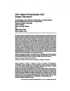
Figure 1. Turbo decoding: (a) turbo decoder, (b) SISO, (c) forward backward scheme, (d) butterfly scheme
When decoding parallel concatenated convolutional codes (Figure 1.a), the processing steps are the elementary Soft Input Soft Output (SISO) decoders. These SISO blocks implements the BCJR algorithm [8] which is the optimal algorithm for the maximum a posteriori (MAP) decoding of convolutional codes. In practice, MAP decoding is not used because of its complexity and is approximated by a logMAP or max-log-MAP algorithm [9]. Using input symbols and a priori extrinsic information, each SISO generates a posteriori probabilities (APP). Then APPs are scrambled by interleaver (Π) or deinterleaver (Π-1) to be used in the opposite interleaving domain. Figure 1.b illustrates the main steps of the BCJR algorithm. Firstly, the branch metrics (or γ metrics) between two states represents the probability that a transition occurs between these two states. Secondly, forward recursion (or α recursion) computes the likelihood of all the states in the trellis given the past observations. This processing is recursive as a trellis section (i.e. the likelihood of all states) is computed with the previous trellis section and branch metrics between these sections. Thirdly, backward recursion (or β recursion) computes the likelihood of all the states in the trellis given the future observations. This processing is the same as the forward recursion, but the frame is processed in the backward direction. Finally, once the forward and backward likelihoods of the states are computed, the extrinsic information can be computed from them. Initially, the BCJR algorithm uses the ForwardBackward scheme, depicted in Figure 1.c. However there exist many other schemes such as the butterfly one (Figure 1.d). Number of existing schemes has increased amazingly with parallelization of the BCJR algorithm [10]. This parallelization consists of dividing the frame into windows or sub-blocks. Nevertheless, when parallelization is applied, the ending points of sub-blocks are unknown, except at frame ending points. This indetermination can be overcome with estimations of ending points obtained either by preacquisition or by message passing between neighbouring sub-blocks. To clarify our explanations, the DVB-RCS turbo code [7] example will be used as a reference in the rest of this paper. It is an eight-state double binary circular convolutional turbo code with a frame size ranging from 12 to 216 bytes.
2.2.
ASIP Design Flow
Tradeoffs between ASIC high performance and programmable processor flexibility are achieved by the application of specific instruction set processors (ASIPs) [11]. The use of such processors in embedded SoCs is becoming more and more mandatory due to the increase in application complexity and the emerging of new applications and ever changing standards. Several approaches and frameworks are now proposed by EDA vendors for ASIP design. ASIP design involves, in addition to hardware cores, software development tools like simulators, compilers, assemblers, debuggers and linkers. In one approach, an environment where the designer can select and configure predefined hardware elements to enhance a predefined basic processor core according to the application needs is proposed. User-defined hardware blocks, together with the corresponding instructions, can be added to the processor [14]. In an other approach the designer has full freedom for the ASIP architecture where he uses an Architecture Description Language (ADL) to specify the instruction set and the ASIP architecture [12][13]. In this paper we used the LISATek framework from CoWare Inc. [13] which is based around the LISA ADL [12], allowing the automatic generation of ASIP software development tools, and VHDL, Verilog and SystemC models for hardware synthesis and system integration. For multiprocessor architecture integration and simulation, SystemC is used together with CoWare ConvergenSC framework.
3. ASIP Architecture for Turbo Decoding 3.1.
Context of Architectural Choices
Our aim is to achieve parallel processing of the MAP algorithm using the sub-block-level parallelism as mentioned in section 2.1. The idea is to design a dedicated processor for the sub-block processing. First, such a processor should support the max-logMAP algorithm with a limited sub-block size for double (and simple) binary turbo codes with a maximum of eight states (section 2.1) . Each sub-block will be processed with the butterfly scheme. Thus, two identical operating units are required (one for
(a)
M etrics buffer
future DECISION_A
decision x2
Forward Recursion Unit
M sys M prog x2
RGE_A
M crossAB
M config
M red
x8
RC_A x4
processing matrix
M info_ext
x8
x8
M crossBA
Backward Recursion Unit
B
decision
RGI_A x4
x8
A
Global ALU
x4
info_ext
ASIP
RMC_A
x4
info_ext
Control Unit
RIE_A
(b) RGI_A(i) RC_A(j)
(d)
M etrics buffer
past
>
R_SIZE
zol_inst
RG E_A
zol_loop zol_active branch_active BP C
FE
DC
x0.5
OP F
EX
A D D RESS_ A A D D RESS_ B FPC IN ST
RT_A(i,j)
ST
(c)
RAD D_A (i,j) RMC_A
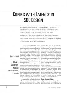
Figure 2. (a) ASIP architecture, (b) Recursion unit, (c) Processing node, (d) Control unit
each recursion). The use of two recursion units (rather than one) allows the processor to support a wide range of decoding schemes. Second, in order to handle the inter sub-block communications, the processor should have adequate communication interfaces. Finally, this processor should retain flexibility while achieving high performance. Application-specific instruction set processors present the ideal solution to achieve such tradeoffs [11].
3.2.
The Architecture of the ASIP
3.2.1 Global View The ASIP is mainly composed of operative and control parts besides its communication interfaces and attached memories (Figure 2.a). The operative part is based on two identical recursion units, corresponding to forward and backward processing in the MAP algorithm. Each unit produces recursion metrics that can be stored in cross memories to be used later by the other unit. Another dedicated memory that contains the trellis description is required for configuration. This trellis description makes possible the implementation of all turbo codes with a maximum of eight states. Incoming systematic and redundant data, in addition to extrinsic information, are stored in external memories attached to the ASIP (sys, red, info_ext). Future and past memories are used to initialize recursion metric values, as the beginning and ending values of each sub-block are not known by the sub-block. 3.2.2 Recursion Unit Each recursion unit is based on Single Instruction Multiple Data (SIMD) architecture in order to exploit trellis
parallelism. In fact, as supported trellis implies up to 32 transitions (Figure 2.b), 32 processing nodes are incorporated in each unit. This could also be decomposed into the maximum number of states supported (8) by the maximum number of decisions per decoding time (4). The organization of these processing nodes inside a recursion unit can be viewed as a processing matrix, where the considered state gives the column and the considered decision the line. With such a representation, each node of the matrix is associated with a transition. A processing node (Figure 2.c) contains two adders, multiplexers, one register for configuration (RT) and an output register (RADD). Two comparators are shared between each set of 4 nodes. Comparisons are executed between two RADD registers neighbouring either linewise or columnwise, depending on the ASIP instructions. The recursion unit also contains a GLOBAL ALU, that performs gamma calculations, metrics actualizations, hard decisions and other global processing. All registers of the recursion unit are 16 bits in width. 3.2.3 Control The ASIP control part is based on a five-stage pipeline (Figure 2.d). These stages are Fetch, Decode, Operand Fetch, Execute, and Store. For this part, several control registers are required. Thus, the sub-block size is fixed in the register R_SIZE, and the current processed symbol inside the recursion unit A (resp. recursion unit B) is stored in ADDRESS_A (resp. ADDRESS_B). These addresses, as well as the program counter and the corresponding instruction, are then pipelined. In addition, the control architecture provides Zero Overhead Loop (ZOL) and branch mechanisms. To alleviate the ASIP instruction set, the ZOL mechanism uses R_SIZE to set the loop size to the value R_SIZE/2 (according to the butterfly scheme chosen).
3.3.
ASIP Instruction Set
The designed instruction set of our ASIP architecture is coded on eight bits. The basic version contains 30 instructions. The following section details the mandatory instructions to perform simple turbo decoding. These instructions are divided into three different classes: control, operative and IO. 3.3.1 Control As mentioned previously, ZOL instruction repeats R_SIZE/2 times the loop on the instructions that follow the ZOL instruction. This instruction was designed in order to match the butterfly scheme for the MAP algorithm. An unconditional branch instruction has also been designed and uses the direct addressing mode. SET_SIZE instruction is used to set the ASIP sub-block size to a maximum size of 64 symbols. 3.3.2 Operative: MAP An ADD instruction is defined and used in two different modes: metrics computation (add m) and extrinsic information computation (add i). According to the ADD mode and to the configuration registers (RT), each processing node selects the desired operands to perform the arithmetic task and to store the result in the corresponding RADD register. In the same way, a MAX instruction was defined with the same modes as an ADD instruction. This basic instruction only performs one comparison. So, in a turbo decoding case, it has to be repeated as often as necessary to obtain either extrinsic information or recursion metrics at the considered address in the sub-block. The basic instruction set also contains the DECISION instruction to produce hard decisions on processed symbols and an ACTU instruction to normalize recursion metrics and avoid overflow. 3.3.3 IO The basic instruction set also provides input and output instructions. With these instructions, parallel multi-accesses are executed in order to: - load decoder input data, input recursion metrics, configuration, - store output recursion metrics, - handle internal cross metrics between the two recursion units, - send extrinsic information packets and hard decisions. Extrinsic information packets contain the four extrinsic pieces of information of the current symbol, and a header. This header contains the sub-block address and an ASIP ID. As the sub-block size is limited to 64, only 6 bits are needed to code sub-block addresses. Taking into consideration a multiple ASIP integration, the choice to code the ASIP ID on 2 bits was made to induce a packet header of 8 bits (cf. section 4.2).
3.4.
DVB-RCS Example
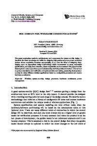
The 26-instruction code, shown in Figure 3, processes continuously a 48-symbol sub-block of a DVB-RCS SISO
on the previously presented ASIP, using the butterfly scheme. LD_CONFIG 0 LD_CONFIG 1 LD_CONFIG 2 LD_CONFIG 3 SET_SIZE 48 _loop: LD_REC ZOL 4 LD_ST add m max m max m ACTU
x24
ZOL 9 LD_CROSS add i max i max i max i ST_EXT add m max m max m ACTU
x24
ST_REC jmp _loop
4 x2 U C xA adm T S 4D L O Z
Figure 3. ASIP code for DVB-RCS example
The first 6-instructions load the required configuration and initialize the recursion metrics. Then the first part of the butterfly is performed using the ZOL instruction. In this loop, two “max m” instructions are needed because DVBRCS is a double binary code. The second part of the butterfly scheme is then executed through another ZOL loop. In this last loop, the “max i” instruction is used three times to compute the extrinsic information of the eight-state DVB-RCS code. Finally, the SISO exports the sub-block ending metrics and program branches to the beginning of the butterfly. Thus, regarding the execution time, 5*N/2 cycles are needed in the first part of the butterfly scheme, and 10*N/2 cycles in the second part, where N is the sub-block size. So about 15*N/2 cycles are needed to process the N symbols of the sub-block. thus 7.5 cycles are roughly needed per symbol.
3.5.
Results
Using a LISATek VHDL Generator, a VHDL description of the ASIP architecture was generated. It was synthesized with a Synopsys Design Compiler in ST 0.09µm (resp. 0.18µm) ASIC technology under worst-case conditions. The synthesized ASIP has a maximum clock frequency of 335 (resp. 180) MHz and occupies about 97 (resp. 93) KGates (equivalent). This means that a single processor, running the two SISO of 6 turbo iterations over a DVB-RCS code, will potentially have a throughput of 7.4 (resp. 4) Mbit/s.
4. Multiprocessor Turbo Decoding A multiprocessor architecture constitutes an ideal candidate for delivering the high computation and communication rates required by the new digital communication standards while preserving flexibility through software programming. In the previous section, an ASIP for parallel turbo decoding with its attached memories and communication interfaces was presented. This ASIP can be used for multiprocessing, where SISO computation is mapped on ASIPs while interleaving is mapped on communication resources.
In state-of-the-art multiprocessors turbo decoding, this interleaving is considered as a limiting factor. In fact, in sub-block level parallelism, the scramble property of interleaving can induce conflicts in communication resources. This forces the communication network to store information until the targeted sub-block can process it. Of course, network buffering resources, and consequently time needed to interleave information, increase with the number of processors. This problem is currently solved by minimizing interleaving delay, with specific communication networks [5]. In the following sections, a new approach is proposed to tackle interleaving problems, and then a turbo decoding multiprocessor architecture is described.
4.1.
Shuffling for Interleaving Transparency
Shuffling was introduced in [16] to improve performance in iterative decoding codes, with better extrinsic information management. In standard decoding, after each iteration, each component decoder delivers extrinsic messages to other decoders which use these messages as a priori values at the next iteration. In shuffled decoding, decoders work in parallel in interleaved and desinterleaved domains. Decoders do not wait until the end of iterations to send extrinsic messages to other decoders and to use received extrinsic messages. Thus decoders use more reliable a priori information. Nevertheless, to preserve BER performance, shuffling requires additional iterations. The ratio between iterations in the serial case and the shuffling case defines the efficiency of the shuffling. This appears as a constant factor (typically between 1.2 and 1.9) depending on the interleaving rules. Shuffling turbo decoding can be seen as concurrent decoding and interleaving. Consequently, communication time overlaps with the computation time. If shuffled turbo decoding is strictly applied as presented in [16], each decoder restarts a new iteration only when all extrinsic messages of the other decoders have been completely received. This delay (network propagation time) leads to
synchronization between processors and communication network. Thus, communication is partially overlapped by the processor load. To overcome this communication overhead, we propose that processors restart a new iteration without waiting for all incoming extrinsic messages. In the case of communication networks with low latency, simulations realized on the DVB-RCS code with this modified shuffled turbo decoding have shown negligible performance degradation in comparison with shuffled turbo decoding. Network latency should not exceed the time required for few APP emissions.
4.2.
ASIP-based Multiprocessor Architecture
In order to use the modified shuffled turbo decoding technique presented above, half of the processors have to be mapped on each interleaving domain. Then, in each domain, each sub-block is mapped on a processor. Using the proposed ASIP architecture (section 3), Figure 4 presents a 4-ASIP turbo decoder architecture where each SISO is implemented using two ASIPs. In this figure, three kinds of networks are used: data interface network, state metric network, and extrinsic information network. These networks take advantage of packet switching communication [15]. First, the data interface network is used to dispatch new frame data to ASIPs and, concurrently, to gather output data from ASIPs. Second, the state metric network makes intra SISO exchanges possible between neighbouring ASIPs (subblocks). It is a set of buffers between neighbouring processors, reflecting the trellis termination strategy. Thus, with a circular trellis termination strategy, i.e. ending and beginning states are identical, a buffer between the first and last ASIP is mandatory (Figure 4). Finally, the extrinsic information network is based on routers to make inter SISO exchanges possible between ASIPs. As the proposed ASIP supports the butterfly scheme, two packets can be sent on this network per
IO_IF
data interface network
x2
M sys x2
M red
x2
ASIP1
x4
x4
M info_ext
M info_ext
past
ASIP3
M sys x2
M red
past
Metrics buffer future
Metrics buffer
Router
future
x2
M sys x2
M red
x2
ASIP0
x4
x4
M info_ext
M info_ext
ASIP2
past
past
future
future
Metrics buffer
M sys x2
M red
Metrics buffer
state metric network
SISO0
extrinsic information network
SISO1
Figure 4. ASIP based multiprocessor architecture for turbo decoding
emission and per ASIP. Packet headers are used by routers to perform routing and interleaving. A router contains a part of the interleaving or desinterleaving table and buffering mechanisms to support up to four input ports and four output ports. So the basic router can only support four processors as ASIP ID is coded on 2 bits (cf. section 3.3.3). For architectures with more than four processors, several routers are needed. In this case, a Benes like network [17], based on the routers described above is proposed. Such a topology is scalable, as routers are identical and configurable. It is also flexible, due to router tables. As routers manage 4 output ports, minimum network latency is equal to log base 4 of the number of ASIPs per SISO. Simulations to evaluate average network latency are in progress.
4.3.
Results
As the modified shuffled turbo decoding is used, the performance of the proposed ASIP-based multiprocessor architecture depends on the number of integrated ASIPs and on shuffling efficiency (see 4.1). Table 1 summarizes multiprocessor turbo decoding performance for DVB-RCS code with 6 iterations and a 1.7 shuffling efficiency. Table 1. Performance for DVB-RCS turbo decoding Number of ASIPs Sub-blocks per SISO Throughput [Mbit/s] @ 0.18µm Throughput [Mbit/s] @ 0.09µm Number of routers
4 2 13.6 25.2 1
8 4 27.2 50.4 2
16 8 54.4 100.8 8
32 16 108.8 201.6 16
Compared to the results presented for simple binary turbo codes [4] (22.64 Mbit/s with 16 ASIPs and 5 iterations @ 0.18µm), our platform achieves equivalent performance1 and a better flexibility by supporting double (and simple) binary turbo codes up to eight states.
5. Conclusion In order to meet flexibility and performance constraints of current and future digital communication applications, an increasing number of application-specific instruction-set processors combined with dedicated communication and memory infrastructures are required. In this paper, we have presented a flexible and scalable multiprocessor architecture based on a new ASIP architecture for high throughput turbo decoding. The ASIP has a dedicated SIMD architecture with a specialized, extensible instruction-set and 5-stage pipeline control. The memory architecture and communication interfaces allow for the efficient assembling of multiple ASIP cores. We have illustrated how the modified shuffled turbo decoding technique can be used to resolve an interleaving bottleneck. Using this technique and sub-block level parallelism, the proposed ASIP-based multiprocessor architecture allows a high throughput while preserving 1
With our architecture, throughput for a simple binary turbo decoder is half the throughput of a double binary decoder (DVB-RCS code).
flexibility and scalability thanks to an adequate packet switching communication network. Other experiments and evaluations are being conducted on the proposed architecture model.
References [1] C. Berrou, A. Glavieux, and P. Thitimajshima, “Near Shannon Limit Error-Correcting Coding and Decoding: Turbo-Codes,” in Proc. 1993 International Conference on Communications (ICC’93), Geneva, Switzerland, 1993. [2] D. J. C. MacKay, “Good error-correcting codes based on very sparse matrices,” IEEE Trans. Inf. Theory, vol. 45, pp. 399– 431, Mar. 1999. [3] D. Gnaëdig, E. Boutillon, M. Jezequel, V. Gaudet, G. Gulak, "On Multiple Slice Turbo Code", 3nd International Symposium on Turbo Codes and Related Topics, Brest, France, pp. 343-346, Sept. 2003. [4] F. Gilbert, M. Thul and N. Wehn. “Communication Centric Architectures for Turbo-Decoding on Embedded Multiprocessors”, Proceedings of DATE 2003, Munich. [5] M. J. Thul, F. Gilbert, T. Vogt, G. Kreiselmaier and N. Wehn, “A Scalable System Architecture for High-Throughput Turbo-Decoders”, Journal of VLSI Signal Processing Vol. 39, pages 63-77, Netherlands 2005. [6] A. La Rosa, C. Passerone, F. Gregoretti, and L. Lavagno, “Implementation of a UMTS turbo-decoder on a dynamically reconfigurable platform”, Proceedings of DATE 2004, Paris. [7] C. Douillard, M. Jezequel, C. Berrou, N. Brengarth, J. Tousch, N. Pham, “The Turbo Code Standard for DVBRCS”, 2nd International Symposium on Turbo Codes & Related Topics, Brest, France, 2000. p. 535-538. [8] L. Bahl, J. Cocke, F. Jelinek, and J. Raviv, “Optimal decoding of linear codes for minimizing symbol error rate,” IEEE Trans. Inf. Theory, vol. IT-20, pp. 284–287, Mar. 1974. [9] P. Robertson, P. Hoeher, and E. Villebrun, “Optimal and SubOptimal Maximum a Posteriori Algorithms Suitable for Turbo Decoding,” European Transactions on Telecommunications (ETT), vol. 8, no. 2, 1997, pp. 119–125. [10] Y. Zhang and K.K. Parhi, “Parallel Turbo decoding”, Proceedings of the International Symposium on Circuits and Systems, volume 2, 23-26 May 2004 Page(s):II - 509-12. [11] A. Oraioglu, A. Veidenbaum, “Application Specific Microprocessors” (Guest Editors Introduction), IEEE Design & Test Magazine, Jan/Feb, 2003. [12] A. Hoffmann, O. Schliebusch, A. Nohl, G. Braun, and H. Meyr, “A Methodology for the Design of Application Specific Instruction Set Processors (ASIP) Using the Machine Description Language LISA”. In Proceedings of the ICCAD, San Jose, USA, Nov. 2001. [13] CoWare Inc., http://www.coware.com/ [14] Tensilica Inc, http://www.tensilica.com/ [15] L. Benini and G.D. Micheli, “Networks on Chips: A New SoC Paradigm,” IEEE Computer, vol. 35, no. 1, 2002, pp. 70–78. [16] Juntan Zhang, Fossorier, M.P.C., “Shuffled iterative decoding”, IEEE Transactions on Communications Volume 53, Issue 2, Feb. 2005 Page(s):209 – 213. [17] V. E. Benes, “Mathematical Theory of Connecting Network and Telephone Trafic”, New York, NY: Academic, 1965.