IEEE TRANSACTIONS ON POWER SYSTEMS, VOL. 23, NO. 2, MAY 2008
545
Assessing Transient Response of DFIG-Based Wind Plants—The Influence of Model Simplifications and Parameters Mustafa Kayikçi and J. V. Milanovic´, Senior Member, IEEE
Abstract—There has been a fast growing demand for the application of doubly fed induction generators (DFIG) in wind power plants in recent years. They have in particular dominated the market in last two years. DFIG is an ideal candidate to satisfy the requirements of the recently proposed challenging grid codes. However, many uncertainties still exist or at least there are no published reports regarding validated comprehensive DFIG models. This paper attempts to clarify the existing ambiguities in modelling of DFIG under various operating conditions using the power system analysis package DIgSILENT PowerFactory. This paper uses available DFIG models and investigates/demonstrates the influence of various model parameters and simplifications (for both mechanical and electrical subsystems) on DFIG-based wind plant transient responses. It further explores and compares the performance of different crowbar protection and rotor side converter restart schemes. Realistic operational limits, such as current margins and PWM modulation limits, are taken into account in all simulations. Index Terms—Doubly fed induction generators (DFIG) modelling, transient operation, wind plants.
I. INTRODUCTION
W
ITH the envisaged demand and integration of wind power into the power system, simulation studies and model validation [1] become extremely important. Currently, the doubly fed induction generator (DFIG) wind turbines dominate the market due to cost-effective provision of variable-speed operation. Their ability to control electrical torque and reactive power offer superior performance concerning system stability. Adequate modelling of these systems and clear understanding of the effects of different simplifications is paramount if reliable results of simulations of power systems with high penetration of DFIG-based wind plants are sought. The DFIG mathematical models, as any other mathematical model of physical device, are simplified either in order to save computational time or to eliminate the requirement for hard-toobtain data. The wind energy industry is rather opaque regarding
Manuscript received January 10, 2006; revised May 15, 2006. This work was supported in part by the Turkish Government, in part by the Overseas Research Scholarship (ORS) provided by the Universities UK Group, and in part by the EU Framework VI project RISE (FP6-INCO-CT-2004-509161). Paper no. TPWRS-00013-2006. M. Kayikçi is with TNEI Services Ltd., Bainbridge House, Manchester M1 2PW, U.K. (e-mail:
[email protected]). J. V. Milanovic is with the School of Electrical and Electronic Engineering, The University of Manchester, Manchester M60 1QD, U.K. (e-mail:
[email protected]). Color versions of one or more of the figures in this paper are available online at http://ieeexplore.ieee.org. Digital Object Identifier 10.1109/TPWRS.2008.919310
modelling as most of the data is usually confidential or requires rigorous field or laboratory experiments. The effects of some simplifications have been tackled to a certain extent in previously published reports [1]–[6]. The major attempts and their shortcomings are briefly reviewed in the sequel and areas in need of further clarifications pinpointed. Reference [2] provides a list of data necessary for dynamic modelling of wind turbines. Many reports [1]–[5] provided a good overview of the possible simplifications; however, the influences of those on DFIG performance are not usually illustrated through experiments/simulations comparatively (e.g., aerodynamic representation, multi-mass model). Reference [7] proposes a method to simplify aerodynamics to represent mechanical power. Modelling of the aerodynamic efficiency, , has been considered either by numerical approximations or through detailed aerodynamic models of the wind turbine; however, its influence on transient operation of the DFIG has not been illustrated. Reported multi-mass models of the turbine-DFIG shaft [4] failed to show resulting oscillations in active power (P) during transients and did not illustrate the influence of shaft stiffness on those transients. Studies related to mechanical oscillations in turbo-generators shafts [8] on the other hand showed that the shaft stiffness is one of the most important parameters to be considered when behavior of multi-mass systems is investigated. Alternative machine models are discussed in [1]–[4], [9]–[14], and [15] illustrates the influence of saturation on transient current response. The effects of modelling of dc-link have been analyzed in [4] by considering two cases: stiff dc voltage and finite capacitance value; however, the capacitance value was not mentioned and the explanation does not reveal much about the influence of dc-link capacitor. Modelling and particularly the influence of crowbar operation at different DFIG operating speeds have not been illustrated before, though it is significant in case of large disturbances. The influence of crowbar protection, which is a rather crucial element having strong influence on DFIG operation, is presented in [4], [10], and [16]; however, different rotor-side converter restart schemes are not discussed in detail. The influence of crowbar resistance on rotor/stator current responses is investigated in [4] and [15]; however, the effects on transient operation of DFIG and on grid stability have not been considered. Having presented the brief summary and shortcomings of the previously published reports, this paper aims to clarify some of the uncertainties associated with DFIG modelling. It also provides numerous simulation results that illustrate the influence of different parameters and modelling on steady-state and transient operation of DFIG-based wind plants.
0885-8950/$25.00 © 2008 IEEE
546
IEEE TRANSACTIONS ON POWER SYSTEMS, VOL. 23, NO. 2, MAY 2008
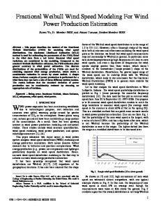
Fig. 1. Single-line diagram of the test network for DFIG system.
Even though the results presented in this paper are obtained using DIgSILENT PowerFactory environment, this paper moves on from “conventional” modelling of the DFIG (e.g., electrical equations of the induction machine with impressed rotor voltages) and analyses various other subsystems of DFIG-based wind turbine, discusses possible simplifications, and presents comparative responses of DFIG when subjected to power system disturbances. Based on that, this paper provides guidelines about required model details and parameters and develops a model suitable for power system analysis. These guidelines can be also used for appropriate simulations in many other power system analysis packages as they usually provide the necessary components to build a DFIG-based wind turbine only. It is still up to the user to link and initialize those components, e.g., machine, mechanical part, converters, dc-link, and controllers (with proper tuning). II. DFIG SYSTEM MODELLING DFIG wind turbines are based on wound-rotor induction machines where the rotor circuit is fed through back-to-back voltage source converters. The network shown in Fig. 1 is built in DIgSILENT PowerFactory in order to analyze various aspects of DFIG modelling and operation. It consists of a single 1.5-MW DFIG generator connected to the external 20-kV grid through a transmission line. Fig. 1 also illustrates the load-flow results when DFIG is operating at rated power. The DFIG generator model is a built-in model [3], [16] which integrates the induction machine and rotor-side converter (RSC). A generic control scheme [16] is employed as shown in Fig. 2. DFIG and RSC are modelled in rotor reference frame (RRF) rotating at generator speed. However, the RSC controller operates in a stator flux-oriented reference frame (SFRF) rotating at grid synchronous speed so axis rotor voltages (or PWM indices) and currents are transformed accordingly for the purpose of this study. Mechanical subsystem including aerodynamics, soft-shaft coupling, and all the controllers as well as the protection system are also custom modelled for this study. RSC control modifies the stator active (P) and reactive (Q) power by regulating the and -axis rotor currents ( and ), respectively. The P reference is obtained from a look-up table (provided by the wind plant operator) representing the maximum power tracking (MPT) algorithm (see Fig. 17). The Q reference can be obtained
Fig. 2. Generic control scheme for the DFIG system in PowerFactory.
Fig. 3. Power/speed controller of the DFIG wind turbine.
either from voltage or power factor controller. The unity power factor is chosen (i.e., ) in this study. Non-windup PI controllers are used to define the rotor current and voltage set-points and rotor voltages, , are applied by defining the PWM indices, , according to (1) Grid-side converter (GSC) controller operates in grid ac voltage reference frame (GCVRF) and regulates the dc-link voltage regardless of the direction of the rotor power flow. GSC has to be synchronized with the ac voltage and a built-in model of a phased-locked loop (PLL) is used to determine the voltage angle. Current and voltage limits of the converters are considered in all controllers [17]. Crowbar protection is discussed in Section IV-B. The power/speed controller consists of two subsystems, namely, maximum power tracking (MPT) and pitch controller as shown in Fig. 3. Pitch control is only activated for wind speeds higher than rated where p.u. and electrical torque is set to maximum according to MPT look-up table. Servo time constant, , is 0.5 s and rate of change of pitch angle, , is /s. In order to initialize the DFIG model, stator power and slip has to be entered while the rest of the parameters are calculated internally. The DFIG machine and turbine data are given in the Appendix. The data supplier also provided a steady-state speed/
KAYIKÇI AND MILANOVIC´ : ASSESSING TRANSIENT RESPONSE OF DFIG-BASED WIND PLANTS
547
TABLE I SPEED/POWER TABLE OF DFIG OBTAINED THROUGH SIMULATION
Fig. 4. Influence of speed variation on mechanical power (solid) and torque (dashed) for constant wind speeds and pitch angle, = 0 (left—C ; wind = 10:5 m/s; right—D ; wind = 11:45 m/s).
power table in order to validate the model. Simulation results (see Table I) are compared against the measured values, and the model is rather accurate as the deviations from the provided data are found to be less than 2.5%. Unfortunately, no measurements were supplied for validation during transient operation. However, the controllers’ action can be verified against the theoretical responses which are further discussed in Section IV. III. MODEL SIMPLIFICATIONS A. Representation of Aerodynamic Rotor For the state-of-the-art modelling of the rotor, blade element momentum method should be used. However, this requires very detailed information, and computations become complicated and lengthy for power system analysis [5]. To overcome this, an algebraic relationship between the wind speed and extracted mechanical power is assumed and described by the aerodynamic efficiency, . In this study characteristic is calculated using an algebraic approximation formula [5] given by (A1) and (A2) in the Appendix (Characteristic curves are also shown in Fig. 12). A look-up table and subsequent interpolation could have been sufficient, as it was done in many previous studies. However, by using an equation-based generic characteristic, the user can determine exactly the maximum power and other operating points. It should be noted that representation is a static approximation and does not consider the aerodynamic transition processes (e.g., dynamic inflow). It was shown by [4] that dynamic inflow phenomenon manifest itself through overshoots in the mechanical torque in case of sudden aerodynamic changes (e.g., sudden pitch angle variations). These are unlikely to affect the power exchange of DFIG with the system significantly but have much greater influence on the mechanical loading of the shaft. In transient stability simulations involving wind turbines, it is usually the wind speed that is assumed to be constant and neither the mechanical power nor the mechanical torque. Mechanical power and torque depend not only on wind speed but on the generator speed as well. In other words, they depend on the tip-speed ratio, , as long as pitch angle, , is constant. During large disturbances when the generator speed deviates from the pre-fault value, [which depends on ; see (A1)] changes. characteristic is therefore not properly represented with constant power (or torque) assumption. Fig. 4 illustrates the change in mechanical power and torque for % speed variation from the initial operating point (wind speed is assumed constant and ). Two distinct points from the MPT (see
Fig. 5. Effect of including Cp characteristic. Solid—C included, Dashed—C neglected and constant wind power assumed, Dash-dot—C neglected and constant mechanical torque assumed.
Fig. 17) are chosen; , representing the case when maximum power is extracted at 80% loading ( p.u. or 1782 rpm) and , representing the rated conditions ( p.u.) within the fixed-speed region. At point , wind power varies only % for % speed variation since the characteristic is rather flat around the maximum operating point. Thus, constant power may be assumed if turbine is extracting maximum energy (i.e., from to ) as long as the pitch control is not activated. Constant torque assumption, however, will lead to pessimistic results since the change in torque is significant % . On the other hand, at rated power (i.e., in Fig. 17), neither the constant power nor constant torque assumption will be valid as both mechanical power and torque vary with speed. More importantly, during the transients, as soon as the turbine starts accelerating above rated speed (1.2 p.u.), pitch control will increase and reduce the wind power drastically. This is further discussed below. Results of transient simulations with constant wind speed, constant wind power, and constant mechanical torque are compared in Fig. 5 following a three-phase short-circuit applied on transmission line close to a DFIG. In order to keep the speed at 1.2 p.u., is increased up to 6 and wind power is reduced by more than 30%. The difference in active power responses stems from the coupling between the power reference and through MPT table. The speed stays lower than 1.2 p.u. due to slow action of the pitch controller, and hence, active power
548
IEEE TRANSACTIONS ON POWER SYSTEMS, VOL. 23, NO. 2, MAY 2008
Fig. 6. Influence of shaft stiffness on DFIG responses to a three-phase short-circuit. Dash-dot—Original case (K = 2:1 p.u./rad), Dashed—Soft shaft (K = 0:3 p.u./rad), Solid—Lumped mass.
Fig. 7. Influence of MPT look-up table on power oscillations due to soft shaft. P obtained from ! (Dash-dot), filtered wind speed (Solid), filtered generator speed (Dashed).
reference also remains lower than 1 p.u. When is neglected and constant wind power is assumed, mechanical torque does not remain constant but reduces % due to 3% turbine speed increase. Similarly if is neglected and constant mechanical torque is assumed, wind power increases linearly with speed. In conclusion, wind power can be assumed to be constant as shown on the left-hand side of Fig. 4 if DFIG is operating between - (see Fig. 17) with fixed . Constant mechanical torque representation, however, could be misleading in most of the cases. Moreover, for the fixed speed operating region near rated power ( - or % of rated power in this case), a basic aerodynamic representation should be included if DFIG speed increases above the rated during the fault and such causing pitch angle change. In some cases, this fixed speed region can start as low as 40% [2], [4], [16]. Thus, in such cases, during voltage transients, constant wind power or torque assumption becomes invalid if the turbine is generating more than 40% power.
Speed oscillations, however, lead to active power and voltage oscillations. The frequency of shaft oscillations can be calculated by (3) and is in the range of 1.44–4.55 Hz for 0.3–3 p.u./el. rad. (Note: Since the frequency range of these oscillations overlaps with the range of frequencies typical for synchronous generator electromechanical oscillations (0.2-2.5 Hz), a potential resonance between the two may occur [4].)
B. Representation of Shaft Dynamics The shaft system provides a coupling between the turbine rotor and generator rotor. It is suggested in [4] that the shaft dynamics (multi-mass mechanical system) should be included in models, even in variable speed turbines because shaft torsional oscillations may lead to speed and power fluctuations. Alternatively, the two masses can be lumped, referring the inertias to the high speed shaft as in (2), where is the inertia in kgm and is the gear-box ratio (2) Fig. 6 compares DFIG responses for different shaft stiffness values. At , a 300-ms, three-phase short-circuit is applied without triggering the crowbar protection. The original shaft stiffness of the turbine is 2.1 p.u./el.rad. However, if the shaft is softer (e.g., 0.3 p.u./el.rad, [5]), the resulting oscillations have lower frequency and higher magnitude as seen in the figure. Reactive power (Q) control is decoupled from active power (P) control, and it is not affected significantly by shaft dynamics.
(3) where is rad/s (corresponding to 50 Hz system), and are the turbine and generator inertias (in s), respectively. Multi-mass model requires more data (usually very difficult to obtain) and is more complex than the lumped mass model. The results of simulations show that when the shaft system is relatively stiff (shaft stiffness, p.u.), lumped mass model can be applied without loss of accuracy. The origin of active power oscillations is the derivation of power set-point from turbine speed, , according to the MPT characteristic. During steady-state operation, any change in wind speed will cause to vary. Since for any wind speed there is only one resulting in maximum , the generator speed is altered to extract the optimum power from wind (see MPT characteristic in Fig. 17 in the Appendix), whereas, during and after the fault, the variation of is not due to wind speed change but rather due to electrical torque reduction. This is interpreted as wind speed variation at the MPT characteristic, and , which should remain constant under the assumption of constant wind speed, is changed according to . Fig. 7 illustrates the difference between constant and variable according to MPT by presenting the response for a turbine with a soft shaft ( p.u./el.rad) following the same disturbance as in Fig. 6. Instead of , filtered rotor-effective wind speed signal can be used for the MPT characteristic [18]–[20], since the rotor acts as energy buffer and hence as a low-pass filter for the wind. When the is obtained from filtered wind speed (in this case, it is constant), it can be seen in Fig. 7 that there are no P oscillations caused by the soft shaft but it takes much longer for the
KAYIKÇI AND MILANOVIC´ : ASSESSING TRANSIENT RESPONSE OF DFIG-BASED WIND PLANTS
549
Fig. 9. DFIG rotor current response to a short-circuit (with supplying reactive power support). Solid—fifth-order model, Dashed—third-order model.
Fig. 8. Influence of machine model order on DFIG response to a short-circuit. Solid—fifth-order model, Dashed—third-order model.
generator to slow down to its pre-disturbance speed. When is obtained through , its amplitude after the fault is higher due to accelerated rotor. This causes turbine to slow down to the pre-disturbance speed quicker. However, such an artificial increase in reduces the margin for Q generation, which could be critical for recovering dynamic loads. Alternatively, can be filtered for shaft oscillations as suggested by [16] and [21]. Fig. 7 also shows the response for the case where is ob(first-order, with a time contained from low-pass filtered stant of 1 s [21]). It can be seen that the power oscillations are significantly reduced in this case. It was shown in [22] that even with much larger filter time constants, the energy capture is not reduced due to the sluggish response of MPT control. In conclusion, shaft oscillations are not translated into electrical power oscillations as long as the RSC remains in operation to control P (i.e., RSC not blocked by crowbar protection) and is obtained suitably such that it truly represents the MPT characteristic. C. Machine Model Order Fig. 8 compares the difference in DFIG response when different machine models (e.g., third and fifth order) are used. A 350-ms three-phase short-circuit is applied at and crowbar is removed at . Stator flux transients (50-Hz oscillations) in current, P and Q traces are clearly visible if the fifth-order model is used. The observed difference in speed responses can be explained by examining the rotor current and torque responses. In the case of fifth-order model, rotor current decay is longer and the “first torque swing” is positive, resulting in a drop in speed at the instant of fault. By using the third-order model of DFIG, one may fail to appropriately account for the operation of crowbar protection [4]. During the simulations, however, it was found that if DFIG provides Q support, even though rotor phase
A current is higher with fifth-order model as in Fig. 8, overall peak rotor current is lower (see Fig. 9). It should be noted that in Fig. 9, a shallower voltage sag was simulated (20% sag, no crowbar operation) and the increase in d-axis current is due to Q support. This can be explained by the fact that the stator transients are neglected in third-order model so the stator flux is allowed to change abruptly while the rotor currents oppose to that sudden change in order to keep the flux constant. As a result of sudden flux changes, higher rotor currents are induced with the thirdorder model than with the fifth order. Moreover, in the case of fifth-order model, fast DFIG current controllers can react and reduce the rotor currents since they increase slower than with the third-order model. Similar results are also reported in [19], [23], and [24]. Omission of stator flux transients in third-order model allows (unrealistically) fast stator flux changes. Fig. 9 shows the rotor d- and q-axis currents ( and ) in the case of a 500-ms . With voltage sag down to 0.8 p.u. voltage initiated at stator-flux-oriented reference frame (i.e., stator-flux is aligned with the d-axis), q-axis controls electrical torque and d-axis controls the magnetization of the machine. While the transient in q-axis current is higher with fifth-order model than with third-order model, d-axis current change is smaller leading to a prediction of higher total rotor current with third-order model. (Note: Since the magnetization is through the d-axis with third-order model stator flux changes abruptly and causes higher induced rotor currents whereas with the fifth-order model stator flux magnetism is taken into account and stator flux change is slower, hence leading to slightly lower rotor currents.) Using the fifth-order model affects the simulation results but not to the extent that it causes triggering of crowbar operation; therefore, third-order model can be used since converters remain in operation. D. Converter Representation There is a close relationship between the machine model used and the converter detail to be included. For example, it will not be necessary to include semiconductor switching
550
IEEE TRANSACTIONS ON POWER SYSTEMS, VOL. 23, NO. 2, MAY 2008
devices if the first- or third-order model of a DFIG is used since the time period of interest (duration of transients) with the s) than that resulting reduced-order model is much longer ( from the switching frequency inclusion ( ms). Similarly if a fifth-order machine model is used, the dc-link capacitor should be modelled together with fast current controllers. Switching devices can be represented either as an ideal or non-ideal (switching losses, finite modulation frequency, etc. included). The non-ideal representation will result in high frequency ripple in the dc-link which does not influence transient stability calculations [2], [5]. However, modulation and current limits should be taken into account in order to represent the capability of power electronics correctly [17]. Grid side converter (GSC) can be represented either as a controlled current source or current controlled voltage source. The latter requires modelling of very fast current controllers, which is a computational burden. Another level of simplification is neglecting the dc-link dynamics (or capacitor). Employing such simplified GSC models leads to pessimistic results for RSC blocking [4] because the dc capacitor exchanges energy with the rotor circuits during transient events (seen as fluctuations in the dc-link voltage.) Therefore, a model neglecting the dc-link dynamics (capacitor, GSC current controls, etc.) may predict excessive transients in rotor current and crowbar triggering. When dc-link capacitor is neglected in the modelling (assuming stiff dc-voltage), GSC control has to be modified from controlling dc-link voltage such that GSC exchanges the rotor power with the grid (i.e., the dc current of RSC is made equal to the dc current of GSC). Dc-capacitor size effect is illustrated in Fig. 10, where a 100-ms three-phase short-circuit is applied close to DFIG. With a very large capacitor value (stiff dc voltage), high transient rotor power cannot be taken out of the rotor immediately. If the dc voltage is stiff, rotor voltage cannot increase above a certain level during the disturbance due to modulation index limitation ), as can be seen in Fig. 10. With a finite (in this case, capacitor rotor, voltage increases together with the dc voltage; however, if the capacitor value is too small (e.g., 2 mF), this might trigger the dc over-voltage protection. When a smaller capacitor is connected, it is charged up quickly and rotor currents tend to stay below crowbar protection limit (dotted line in rotor current trace). However, it was found that if the fault impedance is slightly lower, such that the voltage drops further 0.005 p.u. or more, then both the full and the simplified model predict RSC blocking. Thus, it can be concluded that the converter and dc-link simplification has a minor influence on the results of transient stability simulations. [Note: Detailed modelling of the converter, current controllers, and machine requires small integration steps. Large time (integration) steps can be used without any loss of accuracy when operating in steady-state, and the time step only needs to be reduced during large transient disturbances when rotor currents deviate significantly from the reference values. Employing variable time step, therefore, will represent the system behavior correctly without slowing down the simulation.] IV. SIMULATION RESULTS AND TRANSIENT RESPONSE Several case studies have been carried out to demonstrate the adequacy of the developed models of DFIG system.
Fig. 10. Influence of dc-link simplification on DFIG response to a short-circuit. Solid—Original case (C = 10 mF), Dash-dot—Small capacitor (C = 2 mF), Dashed—Stiff dc voltage. (Pcap—capacitor charging power).
A. Operation Throughout the Wind Speed Range In order to illustrate the converter and controllers performances, an artificial linear wind series is generated from cut-in wind speed up to cut-off value covering the whole operating region of DFIG as shown in Fig. 11. DFIG is operated at unity power factor. The rotor voltage/current controllers act accordingly with the changing speed such that maximum power is extracted from the wind ( - ), except where the speed has to be kept constant ( - , and - in MPT). regulates electrical torque and controls magnetization, and it is constant since unity power factor operation is chosen. The impressed rotor voltages can be calculated from modulation indices according to (1). The DFIG can be operated at lower speeds in order to extract more power. This operation, however, is limited by the rotor voltage (not current) which is restricted by the modulation limits . These limits determine the lower fixed speed region (A-B). Maximum speed is determined by the mechanical constraints and the converter current rating. Optimum power is extracted from the wind between 6 m/s (1018 rpm, point ) and 10.5 m/s (1782 rpm, point ). At wind speeds higher than 10.5 m/s, turbine is operated at fixed speed due to mechanical constraints and electrical torque is set to maximum (1 p.u.). Total power output of the DFIG is the sum of stator and rotor powers. Rotor power contribution, kW, is significant and is 20% of stator power (not total power) at rated conditions and therefore should not be neglected. RSC rating should be determined not only according to the rotor power but it should also take into account the magnetization of the machine and generation/absorption of Q. The procedure for determining the RSC rating for various operating strategies, including voltage control, can be found in [25], and it is not the subject of this study. When the wind speed exceeds the rated value, pitch controller increases the pitch angle and reduces such that generator speed is limited to rated value. MPT characteristic verified by this simulation is shown in Fig. 17 in the Appendix. The pitch angle does not increase continuously but drops after . This can be best explained by tracing the track which is shown by the dotted line in Fig. 12. The turbine starts
KAYIKÇI AND MILANOVIC´ : ASSESSING TRANSIENT RESPONSE OF DFIG-BASED WIND PLANTS
551
Fig. 12. C characteristic curves for different pitch angles and aerodynamic efficiency track (dotted line for ABCD ; see Fig. 17) when DFIG is operated throughout the wind range.
Fig. 13. DFIG response to a voltage dip for different operating speeds. Solid—Maximum speed (1.2 p.u.), Dashed—Minimum speed (0.68 p.u.).
Fig. 11. Performance of DFIG for a wind series covering the operating region.
B. Influence of Crowbar Protection
with a tip-speed ratio, , of at 4 m/s wind speed (point ) and reaches maximum at (at 6 m/s wind, 1018 rpm). stays at maximum ( - ) until speed reaches 1782 rpm and is allowed to decrease till 1800 rpm, where the pitch controller increases in order to limit the mechanical power to prevent over-speeding. As seen in Fig. 12, moves along the dotted line as is increased. As the wind speed increases, reaches 12.3 , and from this point on, rather than increasing , pitch controller reduces but still achieves the goal of reducing by letting drop further (see track in Fig. 12 for tip-speed ratio between 3 and 4). In other words, the condition: speed p.u. can be kept, even if the pitch angle is reduced. It should be pointed out that the representation in this study is obtained analytically and not experimentally. It is clear from the simulation results that such analytical characteristics should be used with caution for low tip-speed ratios where pitch control action can predict unrealistic results (e.g., reducing pitch angle).
When the stator voltage reduces suddenly to low values, high rotor currents are induced. Such over-current transients may occur at events when fluxes in the machine are forced to change abruptly. Even though these currents last for a quite short period of time, they may damage or even destroy the RSC. In order to prevent this, crowbar protection is activated and the RSC is blocked (simulated by setting to zero), and the rotor is short-circuited through some resistance. Under such conditions, the machine is no longer DFIG but an ordinary induction machine which has no control over P or Q. In this study, RSC is blocked when the rotor current exceeds 2 p.u. ( kA peak value). Two extreme cases, operation at minimum (0.68 p.u.) and maximum speed (1.2 p.u.), are simulated with results shown in Fig. 13. A 500-ms distant three-phase fault is applied at , triggering rotor blocking (crowbar activated). The crowbar is removed 500 ms after the fault clearance (at ) and RSC is restarted. Until the RSC resumes its operation, control over P and Q is lost. In both cases, Q consumption is quite similar since it depends on the deviation from synchronous speed. If
552
IEEE TRANSACTIONS ON POWER SYSTEMS, VOL. 23, NO. 2, MAY 2008
Fig. 15. DFIG response to a short-circuit for different RSC restart times. Fig. 14. DFIG response to a short-circuit for different crowbar impedances (Solid—no crowbar impedance, Dashed—2R , Dotted—20R ).
the turbine is operating in steady state at sub-synchronous speed (in this case, at 32% slip), then during the disturbance, the DFIG behaves as a decelerated induction motor and consumes a significant amount of P (1 MW) as well as Q (2.5 MVAr). The simulation results confirm that the crowbar protection is of vital importance to DFIG systems and that the response of DFIG during large disturbances is unpredictable as it depends significantly on pre-disturbance speed (i.e., it may operate as a generator or as a motor, or the level of Q absorption may vary). 1) Effect of Crowbar Impedance: Fig. 14 shows DFIG response to a 350-ms three-phase short-circuit for different crowbar resistance values. A fifth-order model of DFIG is used in order to fully assess the transient events Three cases are simulated; no resistance, 2 Rotor resistance and . RSC is restarted 200 ms after the disturbance is cleared. Without any crowbar impedance, the rotor current shows oscillatory response during the fault, and even if the RSC tries to resume its control many times, system voltage collapses. However, when a resistance is inserted, oscillations are sufficiently damped and the machine remains stable. The machine behaves like an over-speeding induction machine and consumes a large amount of reactive power while the crowbar protection is active. When the RSC is restarted 200 ms after the fault clearance, another transient occurs and RSC might end up being blocked again if crowbar impedance is not big enough. For example, with an extra impedance of 2 , RSC cannot restart due to the high rotor transients occurring at each restart attempt. It tries to re-synchronize every 500 ms (e.g., at 1 s and 1.5 s), but hardly achieves this at the third attempt at s. During this period, very high currents flow in the rotor and stator circuits which might degrade the lifetime of the insulation. Moreover, voltage tends to stay low due to high consumption by DFIG, which may further cause voltage instability in networks with high motor load. In order to prevent converter blocking again at the RSC re-start, [26] suggests that 400 should be inserted into the rotor circuit following a voltage drop, and that the rotor voltages should be ramped slowly to pre-fault values. If the crowbar impedance is sufficiently big ( in this example), current oscillations are damped and kept low during
the disturbance and the DFIG recovers and RSC restarts successfully. For the DFIG system considered in this study, it is found that the crowbar resistances higher than always results in satisfactory recovery. Further increase of crowbar resistance would result in very low rotor currents, leading to unnecessary electrical torque reduction and over-speeding of the turbine during the disturbance. 2) Effect of RSC Restart: Until a few years ago, DFIG was disconnected from the network as soon as the crowbar protection was activated. However, new grid codes [27] require low-voltage ride-through capability. Therefore, the RSC should be restarted safely once the transient period is over. Fig. 15 shows DFIG response to different RSC restart times. A similar disturbance as in Fig. 14 (350-ms balanced fault) is applied. Three cases are simulated. The RSC is restarted 1) when the initial transient after the disturbance is sufficiently decayed (e.g., 200 ms later), 2) ms after the fault clearance when the voltage has recovered to a safe value (e.g., p.u.), and 3) few hundred ms (200 ms in this example) after the fault clearance, when the transient has decayed and voltage has stabilized at a safe value. It can be seen from Fig. 15 that when the RSC is restarted after the initial transient, it improves voltage by % since the control over and is resumed. If restart procedure is delayed after the fault clearance, then DFIG operates as an induction machine during this period and degrades the performance. During large disturbances (i.e., when crowbar protection activated) depending on the pre-disturbance speed, , DFIG may operate either as a generator (if is super-synchronous) or as a motor (if is sub-synchronous). The worst-case scenario was shown in Fig. 13, where is at minimum and maximum speeds. In both cases, reactive power consumption is significant, pushing the system towards voltage instability. Moreover, in the case of sub-synchronous operation, DFIG absorbs active power and may lead to frequency instability if RSC control is not reestablished fast. Therefore, the RSC should be restarted as soon as the rotor currents decay to a safe value to prevent instability. On the other hand, re-starting converter very soon (i.e., during the voltage sag) may cause tripping of converter again at the fault clearance due to significant voltage (hence flux) change, leading to high induced currents. Fig. 16 compares fast RSC
KAYIKÇI AND MILANOVIC´ : ASSESSING TRANSIENT RESPONSE OF DFIG-BASED WIND PLANTS
Fig. 16. DFIG response to deep (Solid) and shallow (Dashed) voltage sags with fast RSC restart.
re-start cases with two different sag magnitudes. When the RSC is re-started, rotor current is increased to maximum allowed value (0.6 kA, peak). If the fault is cleared under this situation, the transient at the fault clearance becomes as severe as, or even worse than, the one resulting from the fault due to large flux deviation. This induces high rotor currents and the RSC is blocked ms. Thereagain and re-synchronised 200 ms later at fore, even though fast re-starting RSC may result in increased power quality, rigorous analysis is required in order to provide reliable operation. V. CONCLUSION This paper progresses from the electrical equation-based modelling and presents a comparative study on the consequences of simplifications and parameters of various other subsystems forming the DFIG-based wind turbine. The model developed is validated for steady-state operation against the data supplied by the manufacturer, and the transient analysis and controllers’ action are verified through numerous simulations. This paper clearly shows the distinction between constant wind speed, constant wind power, and constant mechanical torque operation of the DFIG. Contrary to common acceptance, it is found that for transient studies, the assumption of constant mechanical power or torque results in unrealistic response. This paper further demonstrates that shaft dynamics results in active power oscillations and may substantially influence the transient recovery of the DFIG, depending on the shaft stiffness. Determining from MPT table is compared for three different strategies, and it is shown that both mechanical and electrical improvement can be made with a suitable method that truly represents MPT characteristic. Shaft oscillations are not translated into electrical power oscillations as long as the RSC remains in operation to control P. Reduction/simplification of the model of converter and induction machine does not significantly influence DFIG transient response. It is also found that, as opposed to common assumption, in certain cases (especially when providing voltage support), third-order induction machine model can predict higher rotor
553
currents compared to a fifth-order model as a result of neglecting stator-flux transients, hence allowing sudden flux changes in third-order model. While q-axis rotor current remains higher with fifth-order model, overall rotor current is higher with a third-order model due to large sudden (as a result of neglecting the stator flux) increase in d-axis rotor current which provides magnetization. Comparison of the results obtained with realistic values of dc-link capacitor with those obtained with stiff dc-link voltage capacitor) showed that dc voltage can be assumed con(or stant and that it has small influence on transient operation of DFIG and crowbar insertion. It was also found that the increase in dc-link voltage increases the rotor voltage which in turn reduces the rotor current for a given rotor power during the disturbance. This reduction in rotor current, however, is not large. Even though with stiff dc voltage one may fail to predict crowbar protection, there is negligible difference (0.5% voltage margin) compared to variable dc voltage with a dc capacitor. The developed model is verified by illustrating diverse DFIG variables for the full speed range from cut-in to cut-off wind speed. It was found that the analytical characteristics can predict unrealistic results (e.g., decreasing pitch angle for increasing wind speeds) during high wind speeds when the tipspeed ratio is low since the characteristic curves for different pitch angles converge. This paper also presented the unpredictable nature of DFIG during large disturbances when RSC is blocked. During the transient, DFIG may operate anywhere from absorbing (i.e., motor) to supplying rated active power, depending on pre-disturbance speed. Moreover, absorption of reactive power depends on the deviation from the synchronous speed. The voltage recovery following a close fault depends significantly on the crowbar resistance. Too low resistances may cause instability or unsuccessful RSC re-start, whereas very high values may cause overspeeding due to reduced electrical torque. Finally, this paper demonstrated that the RSC restarting sequence should be chosen cautiously. On one hand, fast RSC re-start may cause blocking of converter again at the fault clearance (depending on the voltage during the sag, i.e., sudden voltage/flux change at the fault clearance), and on the other, it may improve power quality by quickly resuming regulation of active/reactive power. APPENDIX Approximation formulae used for calculation of aerodynamic efficiency
(A1) (A2) where
is the pitch angle and
is the tip speed ratio [5].
554
IEEE TRANSACTIONS ON POWER SYSTEMS, VOL. 23, NO. 2, MAY 2008
Fig. 17. MPT characteristic (ABCD , dotted line).
Induction machine equivalent circuit values (in ), per-phase, stator-referred: Stator resistance Rotor resistance Stator leakage reactance Rotor leakage reactance Magnetizing reactance Induction machine and turbine data: Rated stator power Rated stator voltage Rated rotor voltage Rated DC-link voltage Machine inertia Turbine inertia
kW V V V s s
REFERENCES [1] IEA Wind R&D Annex 21, , “Dynamic models of wind farms for power system studies,” in Proc. Workshop EWEC 2006, Athens, Greece, 2006. [2] J. T. G. Pierik et al., Electrical and Control Aspects of Offshore Wind Turbines II, The Netherlands, Tech. Rep. ECN-C-04-050(-051), ECN, 2004, vol. 1–2. [3] M. Poller, “Doubly-fed induction machine models for stability assessment of wind farms,” in Proc. IEEE Power Tech Bologna 2003, Jun. 2003, vol. 3. [4] V. Akhmatov, “Analysis of dynamic behaviour of electric power systems with large amount of wind power,” Ph.D. dissertation, Elect. Power Eng., Orsted-DTU, Tech. Univ. Denmark, Lyngby, 2003. [5] J. G. Slootweg, “Wind power: Modelling and impact on power system dynamics,” Ph.D. dissertation, Tech. Univ. Delft, Delft, The Netherlands, 2003. [6] Dynamic Modelling of Doubly-Fed Induction Machine Wind-Generators, Aug. 2003, DIgSILENT GmbH Technical documentation, Germany. [7] J. Soens, J. Driesen, and R. Belmans, “Equivalent transfer function for a variable-speed wind turbine in power system dynamic simulations,” Int. J. Distrib. Energy Res., vol. 1, no. 2, pp. 111–133, Apr.–Jun. 2005. [8] J. V. Milanovic, “The influence of shaft spring constant uncertainty on torsional modes of turbogenerator,” IEEE Trans. Energy Convers., vol. 13, no. 2, pp. 170–175, Jun. 1998.
[9] J. B. Ekanayake, L. Holdsworth, and N. Jenkins, “Comparison of 5th order and 3rd order machine models for doubly fed induction generator (DFIG) wind turbines,” Elect. Power Syst. Res., vol. 67, pp. 207–215, 2003. [10] F. Koch, F. Shewarega, and I. Erlich, “Alternative models of the doubly-fed induction machine of power system dynamic analysis,” in Int. Conf. New and Renewable Energy Technologies for Sustainable Development, Evora, Portugal, Jun. 28–Jul. 1, 2004. [11] J. E. McArdle, “Dynamic modelling of wind turbine generators and the impact on small lightly interconnected grids,” Wind Eng., vol. 28, pp. 57–74, 2004. [12] A. Petersson, T. Thiringer, L. Harnefors, and T. Petru, “Modeling and experimental verification of grid interaction of a DFIG wind turbine,” IEEE Trans. Energy Convers., vol. 20, no. 4, pp. 878–886, Dec. 2005. [13] F. Iov, A. D. Hansen, F. Blaabjerg, and T. J. Larsen, “Analysis of reduced order models for large wound-rotor induction generators in wind turbine applications,” in Proc. PCIM Europe 2003, Nürnberg, Germany, 2003. [14] A. D. Hansen, P. Sørensen, T. Lund, and H. Bindner, “Reduced models of doubly fed induction generator system for wind turbine simulations,” Wind Energy, 2005, accepted for publication. [15] A. Perdana, O. Carlson, and J. Persson, “Dynamic response of grid-connected wind with doubly fed induction generator during disturbances,” in Proc. Nordic Wind Power Conf.’04, Göteborg, Sweden, 2004, Chalmers Univ. Technology. [16] A. D. Hansen et al., Dynamic Wind Turbine Models in Power System Simulation Tool DIgSILENT, Denmark, Risø report Risø-R-1400(EN), 2004. [17] C. A. Cañizares, M. Pozzi, S. Corsi, and E. Uzunovic, “STATCOM modeling for voltage and angle stability studies,” Int. J. Elect. Power Energy Syst., vol. 25, no. 6, pp. 431–441, Jun. 2003. [18] C. H. Weigand, H. K. Lauw, and D. A. Marckx, Variable-Speed Generation Subsystem using the Doubly Fed Generator (Nov. 2000), NREL/SR-500-27066, Golden, CO: NREL. [19] M. S. Múgica, A. M. Urkiola, M. R. Vidal, and R. R. Redondo, “Comparison of dynamic models for wind turbine grid integration studies,” in Proc. Eur. Wind Energy Conf., London, U.K., Dec. 2004. [20] S. A. Papathanassiou and M. P. Papadopoulos, “Dynamic behavior of variable speed wind turbines under stochastic wind,” IEEE Trans. Energy Convers., vol. 14, no. 4, pp. 1617–1623, Dec. 1999. [21] F. M. Hughes, O. Anaya-Lara, N. Jenkins, and G. Strbac, “Control of DFIG-based wind generation for power network support,” IEEE Trans. Power Syst., vol. 20, no. 4, pp. 1958–1966, Nov. 2005. [22] L. Ran, J. R. Bumby, and P. J. Tavner, “Use of turbine inertia for power smoothing of wind turbines with a DFIG,” in Proc. 11th Int. Conf. Harmonics and Quality of Power, Sep. 12–15, 2004, pp. 106–111. [23] R. J. Koessler, S. Pillutla, L. H. Trinh, and D. L. Dickmander, “Integration of large wind farms into utility grids (Part 1 - Modeling of DFIG),” in Proc. IEEE Power Eng. Soc. General Meeting, Toronto, ON, Canada, Jul. 13-17, 2003. [24] P. Ledesma and J. Usaola, “Effect of neglecting stator transients in doubly fed induction generators models,” IEEE Trans. Energy Convers., vol. 19, no. 2, pp. 459–461, Jun. 2004. [25] M. Kayikci and J. V. Milanovic, “Reactive power control strategies for DFIG based plants,” IEEE Trans. Energy Convers., accepted for publication. [26] J. Morren and S. W. H. de Haan, “Ridethrough of wind turbines with doubly-fed induction generator during a voltage dip,” IEEE Trans. Energy Convers., vol. 20, no. 2, pp. 435–441, Jun. 2005. [27] SP Transmission Ltd., Consultation on Technical Requirements from Wind Farms, 2004. [Online]. Available: http://gso.scottishpower.com/ publicdocs. Mustafa Kayikçi received the B.Eng. degree in electrical engineering from the University of Manchester Institute of Science and Technology (UMIST), Manchester, U.K., in 2003 and the Ph.D. degree in electrical engineering from the University of Manchester (formerly UMIST) in 2007. He is currently with TNEI Services Ltd., Manchester, as a technical consultant. His research interests include power system dynamics and wind power.
Jovica V. Milanovic´ (M’95–SM’98) received the Dipl.Ing. and M.Sc. degrees from the University of Belgrade, Belgrade, Yugoslavia, and the Ph.D. degree from the University of Newcastle, Newcastle, Australia. Currently, he is a Professor of electrical power engineering and Deputy Head of School (Research) in the School of Electrical and Electronic Engineering of the University of Manchester, Manchester, U.K.