chemical formula of, NH2CONH2, indicates that urea can be considered to be ..... [3] Othmer Kirk,Encyclopedia of chemical technology, Vol.- 21. New York:John. Wiley & Sons,2004. [4] Perry R H. Chemical Engineers Handbook, 6th-edition.
ASSIGNMENT 1 1. INTRODUCTION 1.1 MANUFACTURE OF UREA Urea is an important nitrogenous fertilizer. Its utilization is increasing steadily, it being the preferred nitrogen fertilizer worldwide. It is used in solid fertilizer, liquid fertilizer, formaldehyde resins and adhesives. Rouelle first discovered urea in urine in 1773. His discovery was followed by the synthesis of urea from ammonia and cyanic acid by Woehler in 1828. This is considered to be the first synthesis of an organic compound from an inorganic compound. In 1870, Bassarow produced urea by heating ammonium carbamate in a sealed tube in what was the first synthesis of urea by dehydration [1]. The chemical formula of, NH2CONH2, indicates that urea can be considered to be the amide of carbamic acid NH2COOH, or the diamide of carbonic acid CO(OH)2. Fertilizer is generally defined as “any material, organic or inorganic, natural or synthetic, which supplies one or more of the chemical elements required for the plant growth”. The main aim of the fertilizer industry is to provide the primary and secondary nutrients which are required in macro quantities. Primary nutrients are normally supplied through chemical fertilizers. They are chemical compounds containing one or more of the primary nutrients and are generally produced by chemical reactions. Whatever may be the chemical compounds, its most important ingredient for plant growth is the nutrient content. The primary nutrients are Nitrogen, Phosphorus and Potassium. However, their concentration in a chemical fertilizer is expressed as a percentage of total nitrogen (N), available phosphate (P2O5) and soluble K2O. The grade of a fertilizer is expressed as a set of three numbers in the order of percent N, P2O5 and K2O. If a nutrient is missing in a fertilizer, it is represented by a zero. Thus ammonium sulphate is represented by 20.6-0-0.
1
PROCESS AUXILARY AND UTILITY, 140110730001
ASSIGNMENT 1 1.2 PROPERTIES OF UREA: PHYSICAL PROPERTIES OF UREA Urea is a white, odorless, hygroscopic solid. It is non-corrosive. CHEMICAL PROPERTIES OF UREA Molecular weight
: 60.05
Relative humidity
: 60 %
Maximum Nitrogen content
: 46.6 %
Specific gravity
: 1.335
Heat of fusion
: 60 Cal/gm (endothermic)
Heat of solution, in water
: 58 Cal/gm (endothermic)
Bulk density
: 0.74 gm/cc
Table-1.1 SPECIFIC HEAT OF UREA [2] Temperature, O C
Specific heat, Kj / kg O C
0
1.398
50
1.66
100
1.89
150
2.11
2
PROCESS AUXILARY AND UTILITY, 140110730001
ASSIGNMENT 1 1.3 PROCESS TECHNOLOGY Although there are several processes currently used for the manufacture of urea, the underlying principle for all the processes is same. The two main reactions involved are:
1) CO2
+ 2NH3
2) NH2COONH4
NH2COONH4
∆H = -37.4 Kcal/gm mol
NH2CONH2 + H2O
∆H= + 6.3 Kcal/gm mol
Undesirable side reaction taking place is: 3) 2NH2CONH2
NH2CONHCONH2 + NH3
Both 1st & 2nd reactions are equilibrium reactions. The 1st reaction almost goes to completion at 185-190 oC & 180-200 atms. The 2nd reaction (decomposition reaction) is slow and determines the rate of the reaction. Unconverted CO2 & NH3, along with unrecompensed carbamate, must be recovered and re-used. This is a troublesome step. The synthesis is further complicated by the formation of a dimer called biuret, NH2CONHCONH2, which must be kept low because it adversely affects the growth of some plants [3]. 1.4 PROCESS IN GENERAL Ammonia & CO2 are compressed separately and fed to the high pressure (180 atms) autoclave. Which must be water cooled due to the highly exothermic nature of the reaction. A mixture of urea, ammonium carbamate, H2O and unreacted ( NH3+CO2) is produced. This liquid effluent is let down to 27 atms and fed to a special flash-evaporator containing a gas-liquid separator and condenser. Unreacted NH3, CO2 & H2O are thus removed & recycled. An aqueous solution of carbamate-urea is passed to the atmospheric flash drum where further decomposition of carbamate takes place. The off gases from this step can either be recycled or sent to NH3 processes for making chemical fertilizer [4]. The 80 % aqueous urea solution can be used as it is, or sent to a vacuum evaporator to obtain molten urea containing less than 1 % water. The molten mass is then sprayed into a prilling tower. To avoid formation of biuret and keep it less than 1 %, the temperature must be kept just above the melting point for processing times of 1-2 seconds in this phase of the operation [5].
3
PROCESS AUXILARY AND UTILITY, 140110730001
ASSIGNMENT 1 2. SNAMPROGETTI AMMONIA STRIPPING PROCESS 2.1 MANUFACTURING PROCESS In the reactor, when liquid ammonia reacts with compressed CO2 (at 162 atp) at high temperature & pressure gives urea according to the following reactions:
2NH3 + CO2
NH2COONH4
exothermic
NH2COONH4
NH2CONH2 + H2O
endothermic
As the reactions are reversible in nature only partial conversion occurs in the reactor. Urea solution consisting of Urea ,Carbamate, Water & unconverted CO2 & NH3 are fed into the stripper where stripping action of NH3 favours decomposition of carbamate and hence 80% of carbamate is decomposed here. Pressure in the stripper is same as that of the reactor. Urea solution from the stripper is sent to Medium pressure decomposer where Urea purification takes place by the dehydration of the Carbamate. Urea solution is further purified in Low pressure decomposer. Off gases from the M P decomposer & L P decomposer are sent to the Medium pressure condenser & Medium pressure absorber for the recovery of unconverted Ammonia. In this way 71.12% of Urea solution resulting from L P decomposer is sent to Vacuum concentrators operating in two stages: 1) 1st Vacuum evaporator. 2) 2nd Vacuum evaporator
Finally, 98 % molten urea is sent to the Prilling Towers where Urea prills are formed by passing a current of cold air in the tower from the bottom. Proper size Urea prills are sent to bagging section through belt conveyors. In bagging section, coating of Urea prills may be done if required. Oversized Urea prills or lumps are sent to lump dissolving tank [6].
4
PROCESS AUXILARY AND UTILITY, 140110730001
ASSIGNMENT 1 2.2 UREA SYNTHESIS NH3 & CO2 react under specific concentration, temperature & pressure conditions to form Urea as per the following reactions:
1) CO2 (g) + 2NH3(g) NH2COONH4 (s) ;
∆H = -37.64 kcal/gm mol
2) NH2COONH4(s) NH2CONH2 (s) + H2O (l) ; ∆H=6.32 kcal/gm mol -----------------------------------------------------------------------------------------------------------CO2 (g) + 2NH3 (g) NH2CONH2 (s) + H2O (l); ∆H = -31.32 kcal/gm mol So, overall urea synthesis is exothermic, releasing heat 31.32 kcal/gm mol at standard conditions of 1 atm pressure & 25°C. But actual heat available in an urea synthesis reaction will be only 5.74 kcal/gm mol because of the heat lost in evaporation of liquid NH3, evaporation of water & melting of urea. This is based on the actual plant data [7]. Further energy is consumed in feeding CO2 & NH3 at high temperature & pressure, in recycling of carbamate, in vacuum concentration of urea , for operating different pumps & compressors etc. which altogether makes the urea production energy consuming. 2.3 SNAMPROGETTI STRIPPING PROCESS Formation of urea from ammonia & carbon-di-oxide takes place through reversible reactions with formation of ammonium carbamate as intermediate product. Now, success of any urea manufacturing process depends on how economically we can recycle carbamate to the reactor. Snamprogetti process of urea manufacturing accomplishes the above task by stripping process [8]. NH2COONH4 (s)
2NH3 (g) + CO2 (g)
∆H = + 37.4 Kcal/gm-mole
This reaction involves increase in volume & absorption of heat. Thus this reaction will be favored by decrease in pressure & increase in temp. Moreover decreasing the partial pressure of either of the products will also favor the forward reaction. Process based on first principle of decrease in pressure & decrease in temp is called conventional process , whereas process based on increase/decrease of partial pressures of NH3 or CO2 is called stripping process. According to above equation we have: 2
K = (pNH3) *(pCO2) [where, K= equilibrium constant]
5
PROCESS AUXILARY AND UTILITY, 140110730001
ASSIGNMENT 1 The stripping is effected at synthesis pressure itself using CO2 or NH3 as stripping agent . If CO2 is selected, it is to be supplied to the decomposers/stripper as in Stamicarbon CO2 stripping process. if NH3 is selected, it is to be obtained from the system itself because excess NH3 is present in the reactor as in Snam’s process. CO2 stripping is advantageous because introducing CO2 increase pCO2. So pNH3 will be reduced to maintain P constant as P = pCO2 + pNH3. At a particular temp K is constant so when pNH3 is reduced to keep K constant , carbamate will be reduced much faster by decomposition as pNH3 appears in the equilibrium equation with a power of two. Selection of 1st stage decomposition should be in such a way that min water evaporates because the recovered gases go along with the carbamate to reactor again & if water enters reactor, production will be affected adversely due to hydrolysis of urea. So, stage wise decomposition of carbamate is done. Second consideration in favor of isobaric stripping is that higher carbamate recycles pressure results in condensation at higher temp & that recovery in the form of low pressure steam. This is why stage wise reduction in pressure is practiced [2]. 3. PROCESS DESCRIPTION The urea production process takes place through the following main operations [9]: 1) Urea synthesis & high pressure recovery. 2) Urea purification & low pressure recovery. 3) Urea concentration. 4) Urea prilling. Urea is synthesized from liquid ammonia & gaseous carbon-di-oxide. . The carbon di oxide drawn from battery limits at about 1.6 atp pressure & about 40°C temp is compressed in a centrifugal compressor up to 162 apt. A small quantity of air is added to the CO2 compressor suction in order to passivate the stainless steel surfaces. Thus, protecting them from corrosion due to both the reagent & the reaction product .
6
PROCESS AUXILARY AND UTILITY, 140110730001
ASSIGNMENT 1
The liquid ammonia coming directly from battery limits is collected in the ammonia receiver tank from where it is drawn to & compessed at about 23 atp pressure by means of centrifugal pump. Part of this ammonia is sent to medium pressure absorber & remaining part enters the high pressure synthesis loop. The NH3 of this synthesis loop is compressed to a pressure of about 240 atp. Before entering the reactor it is used as a driving fluid in the carbamate ejector, where the carbamate coming from carbamate separator is compressed up to synthesis pressure. The liquid mixture of ammonia & carbamate enters the reactor where it reacts with compressed CO2. In the reactor the NH3 & gaseous CO2 react to form amm. Carbamate , a portion of which dehydrates to form urea & water . The fraction of carbamate that dehydrates is determined by the ratios of various reactants, operating temp, the residence time in the reactor & reaction pressure. The mole ratio of NH3 / CO2 is around 2:1; the mole ratio of water to CO2 is around 0.67: 1. 2NH3 (g) + CO2 (g)
NH2COONH4 (s) ;
exothermic
NH2COONH4 (s)
NH2CONH2 (s) + H2O (l) ;
endothermic
In the synthesis conditions ( T= 190°C , P= 154 atm) , the 1st reaction occurs rapidly & is completed . The 2nd reaction occurs slowly & determines the reactor volume. Urea reactor is a plug flow type with 10 no.s of sieve trays to avoid back mixing & to avoid escape of gaseous CO2 which must react in the lower part of the reactor. Stage wise decomposition is carried out to reduce water carry over to the reactor which could adversely affect conversion. Urea solution containing urea, carbonate , H2O & unconverted CO2 & NH3 enters the high pressure stripper where the pressure is same as that of the reactor . The mixture is heated as it flows down the falling film exchangers. The CO2 content of the solution is reduced by the stripping action of NH3 as it boils out of the solution. The carbamate decomposition heat is supplied by 24 atp steam. The overhead gases from stripper and the
7
PROCESS AUXILARY AND UTILITY, 140110730001
ASSIGNMENT 1 recovered solution from the MP absorber, all flow to the high pressure carbamte condenser through mixer, where total mixture, except for a few inerts is condensed & recycled to the reactor by means of carbamate ejector . Condensing the gases at high temp & pressure permits the recovery of condensation heat in the production of steam at 4.5 atp in the high pressure carbamate condenser. From the top of the carbamate separator the incondensable gases come out consisting of inerts & a little quantity of NH3 & CO2 unreacted in the condenser. These are sent to the bottom of MP decomposer.
8
PROCESS AUXILARY AND UTILITY, 140110730001
ASSIGNMENT 1
9
PROCESS AUXILARY AND UTILITY, 140110730001
ASSIGNMENT 1 UREA PURIFICATION & LOW PRESSURE RECOVERY Urea purification takes place in two stages at decreasing pressure as follows: 1st stage at 18 atp pressure, i.e, MP decomposer 2nd stage at 4.5 atp pressure ,i.e, LP decomposer
1st stage purification & recovery stage at 18 atp: It is falling film type MP decomposer. It is divided into 2 parts : Top separator, where the released flash gases , the solution enters the tube bundle & decomposition section where the residual carbamate is decomposed & required heat is supplied by means of 24 atp steam condensate flowing out of the stripper [4]. 2nd purification & recovery stage at 4.5 atp: The solution leaving the bottom of MP decomposer is expanded at 4.5 atp pressure& enters the LP decomposer (falling film type). This is again divided in to two parts :top separator where the released flash gases are removed before the solution enters the tube bundle . Decomposition section where the last residual carbamate is decomposed & the required heat is supplied by means of steam saturated at 4.5 atp [4].
UREA CONCENTRATION Next section is urea concentration & objective is to reduce water content of urea to as low as 1 %. For the purpose a vacuum concentrator in two stages is provided. The solution leaving the LP decomposer bottom with about 72% urea is sent to the 1st vacuum concentrator operating at a pressure of 0.23 atp .The mixed phase coming out enters the gas liquid separator, wherefrom the vapors are extracted by the 1st vacuum system, while the solution enters the 2nd vacuum concentrator operating at a pressure of 0.03 atp . The two concentrators are fed by saturated steam at 4.5 atp . The mixed phase coming out enters the gas liquid separator, wherefrom the vapors are extracted by the 2nd vacuum system.
10
PROCESS AUXILARY AND UTILITY, 140110730001
ASSIGNMENT 1 UREA PRILLING The molten urea leaving the 2nd vacuum separator is sent to the prilling bucket by means of a centrifugal pump. The urea coming out of the bucket in the form of drops fall along the prilling tower & encounters a cold air flow which causes its solidification. The solid prills falling to the bottom of the prilling tower are sent through the screeners to retain lumps only, & then to belt conveyor which carries the product to the automatic weighing machine & to the urea storage sections. Urea lumps by the means of belt conveyor are recycled to the underground tank, where they are dissolved.
4. MATERIAL BALANCE Selected capacity:
4, 50,000 tons/year
No. of working days:
300
Daily production:
4, 50,000/300 = 1500 tons/day
Urea:
62,500 Kg/hr of 98 % purity
Composition of the final product: Urea
:
98 % (61,250 Kg/hr)
Biuret
:
1%
(625 Kg/hr)
Water
:
1%
(625 Kg/hr)
Assumption: Overall conversion to urea is assumed to be 95 %.
MAIN REACTIONS: 1) CO2
+ 2NH3
NH2COONH4
2) NH2COONH4
NH2CONH2 + H2O
3) CO2
NH2CONH2 + H2O
+ 2NH3
(Overall reaction)
Side reaction: 4)2NH2CONH2
11
NH2CONHCONH2 + NH3
PROCESS AUXILARY AND UTILITY, 140110730001
ASSIGNMENT 1 625 Kg/hr of Biuret produced by = (120/103)*625 = 728 Kg/hr of urea (reaction 4) So, urea produced by reaction (2) = 61250 + 728 = 61978 Kg/hr 61978 Kg/hr of urea produced by = (34/60)*61978 = 35,120 Kg/hr NH3 Similarly, CO2 reacted in reaction (1) = (44/60)*61978 = 45,450 Kg/hr Assuming 95 % conversion we get NH3 actually required = 35120/0.95 = 36,968 Kg/hr CO2 actually required = 45450/0.95 = 47,842Kg/hr Now, considering reaction (4): If reaction (3) is 100 % complete then, Urea produced = (60/44)*47842 = 65,239 Kg/hr But, for 95 % conversion Urea produced = 0.95*65,239 = 61,977 Kg/hr Therefore, Urea converted to Biuret & NH3 = 61,977 – 61,250 = 727 Kg/hr So, from reaction (4) Biuret produced = (103/120)*727 = 624 Kg/hr Water produced in reaction (2) = (18/60)*61978 = 18,593 Kg/hr At reactor’s exit (Urea = 34 %) Flow rate of stream = 61,250/0.34 = 1, 80,147 Kg/hr NH3 reacted in reaction (1) = (34/60)*61977 = 35,120 Kg/hr NH3 produced in reaction (4) = (17/120)*727 = 103 Kg/hr So, NH3 unreacted = 36968 – 35120 + 103 = 1951 Kg/hr CO2 reacted in reaction (1) = (44/60)*61977 = 45450 Kg/hr Therefore, CO2 unreacted = 47842 – 45450 = 2392 Kg/hr Now, Flow rate of stream at reactor’s exit – (flow rate of urea+CO2+NH3+water+biuret) = Flow rate of carbamate 1, 80,147- (61,250 + 2392 + 1951 +18,593 + 624) = 95,337 Kg/hr
12
PROCESS AUXILARY AND UTILITY, 140110730001
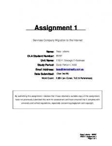
ASSIGNMENT 1 4.1 MATERIAL BALANCE FOR REACTOR
Fig 4.1 Flow of material across reactor [10]
Table 4.1 Flow of material across reactor [10] INPUT MATERIAL
OUTPUT FLOW RATE (Kg/hr)
%
MATERIAL
FLOW RATE (Kg/hr) %
1951
1.08
2392
1.32
61250 18593 624 95,337 180147
34 10.32 0.36 52.92 100
Feed NH3 (liq)
36968
43.59
Unreacted NH3 (liq)
CO2
47842
56.41
CO2 (gas)
Total
84810
100
Recycle CARBAMATE
95337
100
(gas)
TOTAL
18017
13
100
Products UREA WATER BIURET CARBAMATE
PROCESS AUXILARY AND UTILITY, 140110730001
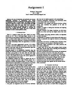
ASSIGNMENT 1 4.2 MATERIAL BALANCE FOR STRIPPER
Fig 4.2 Flow of material across stripper [10] Since, no reaction takes place in the stripper & only carbamate gets recycled back to the reactor. Therefore, the amount of ammonia, carbon-di-oxide, water & biuret in the outlet stream of stripper will be same as it was in the inlet stream. Table 4.2 Flow of material across stripper [10] INPUT MATERIAL NH3
1951
1.08
MATERIAL Bottom product NH3
CO2
2392
1.32
CARBAMATE
95337
52.92
UREA WATER
61250 18593
34 10.32
BIURET
624
0.36
TOTAL
FLOW RATE (Kg/hr) %
180147
14
OUTPUT FLOW RATE (Kg/hr) % 1951
2.30
CO2
2392
2.82
UREA WATER BIURET
61250
72.22
18593 624
21.9 0.76
Total
84810
100
Top product Ammonium carbamate
95337 -
100 -
100 PROCESS AUXILARY AND UTILITY, 140110730001
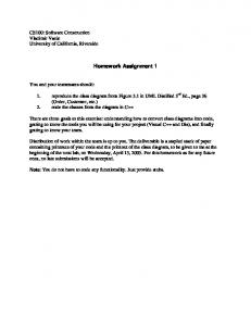
ASSIGNMENT 1 4.3 MATERIAL BALANCE FOR MEDIUM PRESSURE SEPARATOR
Fig 4.3 Flow of material across medium pressure separator [10] The amount of ammonia, carbon-di-oxide ,water & biuret will remain constant as no reaction is taking place. 50 % of ammonia & carbon-di-oxide are assumed to escape from the top of the separator & rest goes with the bottom product. Amount of water & biuret remains constant as no reaction takes place. Table 4.3 Flow of material across medium pressure separator [10] INPUT MATERIAL FLOW RATE (Kg/hr) NH3 1951 CO2 2392 UREA 61250 WATER 18593 BIURET 624
% 2.3 2.82 72.22 21.9 0.76
OUTPUT MATERIAL FLOW RATE (Kg/hr) % NH3 976 1.18 CO2 1196 1.44 UREA 61250 74.11 WATER 18593 22.49 BIURET 624 0.78 Total Losses NH3 CO2
TOTAL
84812
15
100
82,639 975 1196 2171
100 44.91 55.09 100
PROCESS AUXILARY AND UTILITY, 140110730001
ASSIGNMENT 1 4.4 MATERIAL BALANCE FOR LOW PRESSURE SEPARATOR
Fig 4.4 Flow of material across low pressure separator [10]
Remaining ammonia & carbon-di-oxide are assumed to escape from the top.
Table 4.4 Flow of material across low pressure separator [10] INPUT MATERIAL FLOW RATE (Kg/hr)
OUTPUT %
MATERIAL
FLOW RATE (Kg/hr) %
NH3
976
1.18
CO2
1196
1.44
UREA
61250
74.11
UREA
61250
76.11
WATER
18593
22.49
WATER
18593
23
BIURET
624
0.78
BIURET
624
0.79
Total
80467
100
Losses
TOTAL
82639
16
100
NH3
975
44.91
CO2
1196
55.09
2171
100
PROCESS AUXILARY AND UTILITY, 140110730001
ASSIGNMENT 1 4.5 MATERIAL BALANCE FOR VACUUM EVAPORATOR
Fig 4.5 Flow of material across vacuum evaporator [10]
Let x & y be the mass fractions of Urea in feed (F) & product (P) resp. x= 0.7611 (76.11 %) y= 0.9788 (97.88 %) Making urea balance: F.x = P.y 80467*0.7611 = P*0.9788 P = 62574 Kg/hr Overall material balance gives: F=P+E 80467 = 62574 + E E = 17893 kg/hr
17
PROCESS AUXILARY AND UTILITY, 140110730001
ASSIGNMENT 1 Table 4.5 Flow of material across vacuum evaporator [10]
MATERIAL
INPUT FLOW RATE (Kg/hr)
UREA
61250
76.11
UREA
61250
97.88
WATER BIURET
18593 624
23.10 0.79
WATER BIURET
700 624
1.11 1.01
Total
62574
100
Losses WATER
17893
100
TOTAL
80467
%
MATERIAL
OUTPUT FLOW RATE (Kg/hr) %
100
4.6 MATERIAL BALANCE FOR PRILLING TOWER
Fig 4.6 Flow of material across prilling tower [10]
18
PROCESS AUXILARY AND UTILITY, 140110730001
ASSIGNMENT 1 Let x & y be the mass fractions of Urea in feed (F) & product (P) resp. x= 0.9788
(97.88 %)
y= 0.9796
(97.96 %)
Making urea balance: F.x = P.y 62574*0.9788 = P*0.9796 P = 62524 Kg/hr
Table 4.6 Flow of material across prilling tower [10] INPUT
OUTPUT
MATERIAL FLOW RATE (Kg/hr)
%
MATERIAL
FLOW RATE (Kg/hr) %
UREA
61250
97.88
UREA
61250
WATER
700
1.11
WATER
650
1.11
BIURET
624
1.01
BIURET
624
0.93
Total
62,524
100
50
100
97.96
Losses WATER TOTAL
19
62574
100
PROCESS AUXILARY AND UTILITY, 140110730001
ASSIGNMENT 1
REFERENCES: [1]
Shreeve R N. Chemical process industries,3rd edition. New York : McGraw Hill book company,1967
[2]
Dryden’s.
Outlines
of
chemical
technology,
3rd-edition.New
Delhi:Affiliated East west press private limited,2004 [3]
Othmer Kirk,Encyclopedia of chemical technology, Vol.- 21. New York:John Wiley & Sons,2004
[4]
Perry R H. Chemical Engineers Handbook, 6th-edition. New York: McGraw Hill Book Co,1984
[5]
Pozin M E. Fertilizer Manufacture. Moscow:Khimia,1974
[6]
Brownell L E & young E H. ProcessEquipment Design.New York:John Wiley & Sons,1968
[7]
Bhattacharyya B C. Chemical Equipment Design,1st edition. New Delhi:CBS,2003
[8]
Joshi M V. Process Equipment Design, 3rd edition. New delhi:Mcmillan India Limited,2001
[9]
Kern D Q.Process Heat Transfer. New Dehli:Mcgraw Hill Companies,2004
[10] GNFC - BHARUCH (GUJARAT), Plant data.
20
PROCESS AUXILARY AND UTILITY, 140110730001