IEEE TRANSACTIONS ON BIOMEDICAL CIRCUITS AND SYSTEMS, VOL. 8, NO. 4, AUGUST 2014
453
Asynchronous Binaural Spatial Audition Sensor With 2 64 4 Channel Output Shih-Chii Liu, Senior Member, IEEE, André van Schaik, Senior Member, IEEE, Bradley A. Minch, Member, IEEE, and Tobi Delbruck, Senior Member, IEEE
Abstract—This paper proposes an integrated event-based binaural silicon cochlea system aimed at efficient spatial audition and auditory scene analysis. The cochlea chip has a matched pair of digitally-calibrated 64-stage cascaded analog second-order filter banks with 512 pulse-frequency modulated (PFM) address-event representation (AER) outputs. The quality factors (Qs) of channels are individually adjusted by local DACs. The 2P4M 0.35 um CMOS chip consumes an average power of 14 mW including its integrated microphone preamplifiers and biasing circuits. Typical speech data rates are 10 k to 100 k events per second (eps) with peak output rates of 10 Meps. The event timing jitter is 2 us for a 250 mVpp input. It is shown that the computational cost of an event-driven source localization application can be up to 40 times lower when compared to a conventional cross-correlation approach. Index Terms—Address-event representation (AER), audition, cochleas, localization, neuromorphic, spike-based.
I. INTRODUCTION
I
N the field of auditory scene analysis, it is desirable to classify acoustic environments such as speech in soft or loud surroundings; and to classify and localize auditory sources such as human speakers, vehicles, cries of distress, dogs barking, or gunshots. These tasks are conventionally achieved by digital signal processing based on the regular sampling of the auditory input signals at the necessary Nyquist frequency. Sampling frequencies of microphone inputs typically range from 16 kHz to 192 kHz. Although parts of this digital processing have been optimized in specific applications (e.g., 64-point FFT in hearing aids), the resolution and sampling rate dictated by a given application place a lower bound on continuous power consumption. For example, the auditory timing resolution necessary for spatial audition, where a 1 degree change of angle changes interaural Manuscript received April 14, 2013; revised July 10, 2013; accepted August 28, 2013. Date of publication November 08, 2013; date of current version July 24, 2014. This project was supported in part by the Swiss National Science Foundation Grant #200021-126844, the ONR NICOP Grant N00014-05-10916, the Australian Research Council Grant DP0881219, the Samsung Electronics Corporation, ETH Zurich and the University of Zurich. This paper was recommended by Associate Editor B. Shi. S.-C. Liu and T. Delbruck are with the Institute of Neuroinformatics, University of Zurich and ETH Zurich, Switzerland, 8057 Zurich, Switzerland (e-mail:
[email protected];
[email protected]). A. van Schaik is with the MARCS Institute, University of Western Sydney, Penrith, NSW 2751, Australia (e-mail:
[email protected]). B. A. Minch is with Olin College, Needham, MA 02492 USA (e-mail:
[email protected]). Color versions of one or more of the figures in this paper are available online at http://ieeexplore.ieee.org. Digital Object Identifier 10.1109/TBCAS.2013.2281834
delay by at most 6 us with microphones spaced by 10 cm, requires a sample rate in excess of 100 kHz. Although it is possible to reduce power by varying the sample rate dynamically according to set criteria, it is fundamentally interesting to explore an alternate approach inspired by biological audition, which has been optimized by millions of years of evolution. By using biology’s event-driven computational architecture, it may be possible to build embedded auditory scene analysis sensors that function for extended periods on battery or scavenged power. Here we report progress in this direction in the form of a highly integrated binaural silicon cochlea. Biological cochleas use a space-to-rate encoding in which the input sound is encoded as trains of pulses created from the outputs of a set of broadly frequency-selective channels [1]. The pulses are phase-locked for low frequencies and this phase locking disappears for frequencies above around 3 kHz [2]. Encoding the information this way allows sparser sampling of frequency information according to the active frequency channels rather than the maximal sampling rate required to capture all information from a single audio source. Event-based silicon cochleas such as the one proposed here model the basilar membrane (BM) biophysics of biological cochleas as a large number of coupled filter stages, followed by half-wave rectification and asynchronous output quantization in the time domain with transmitted data encoded using the address-event representation (AER) protocol [3]–[11]. A binaural event-based silicon cochlea which efficiently extracts events with spectrally-selective phase timing is desirable for spatial audition tasks [10]–[14]. These events preserve timing of signals arriving to the two ears and post-processing is cheaper because only a sparse stream of events needs to be processed. The proposed sensor builds on a long history of development [15]–[17] by addressing a number of shortcomings of previous work. Previous AER silicon cochlea designs offer either only monaural operation [5]–[7], [35], poor channel matching [5], [10], [18], do not integrate biasing circuits for process, voltage, and temperature tolerant biasing [5], [15], [18], do not integrate microphone preamplifiers [5], [7], [8], [10], [18], or do not include any per-channel calibration capability [5], [8], [10], [18]. None of the prior work has open-sourced host software APIs and algorithms which enable rapid development of application scenarios [19]. The binaural cochlear system described here is the first fully integrated system that combines features of previous silicon cochlea designs that are robust to mismatch, along with novel features for easier programmability of the architecture and operating parameters. The chip includes integrated mi-
1932-4545 © 2013 IEEE. Translations and content mining are permitted for academic research only. Personal use is also permitted, but republication/ redistribution requires IEEE permission. See http://www.ieee.org/publications_standards/publications/rights/index.html for more information.
454
IEEE TRANSACTIONS ON BIOMEDICAL CIRCUITS AND SYSTEMS, VOL. 8, NO. 4, AUGUST 2014
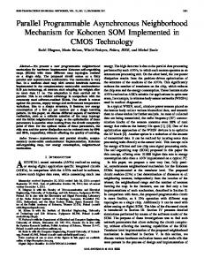
Fig. 1. Cascaded architecture of 64-stage filter bank cochlea for one ear with four PFMs per channel.
crophone preamplifiers [20], [21], local gain adjustment, and on-chip digitally controlled biases [22]. The scanned individual basilar membrane and pulse-frequency modulated (PFM) circuit signals can also be digitized and read into the computer through the USB port. A bus-powered USB board enables easy interfacing to standard PCs for control and processing. The proposed sensor corrects design errors in [23], includes off-chip ADCs for recording audio input, and extends on [23] to report measurements and analysis of the system performance, including local gain control and matching. The remainder of this paper is organized as follows. Section II describes the circuit architecture of the binaural chip. Section III describes the implementation of the system and its characterization. Section IV reports measurement results from the chip; in particular, Section IV.D compares the computational cost of an auditory localization application using an event-driven algorithm versus a sampled cross-correlation approach. Section V concludes the paper. II. CIRCUIT ARCHITECTURE The binaural chip has two separate 64-stage filter banks allowing direct connection to two electret microphones. Each cochlea is implemented by a cascaded second-order filter bank architecture [15], [17], [24] as shown in Fig. 1. In contrast to the cochleas described in [5], [7], [16], [18], which model the fluid coupling with a resistively-coupled bank of bandpass filters, this cochlea does not explicitly implement the fluid coupling because we believe the cascaded architecture [15]–[17] is preferred over the coupled bandpass architecture [5], [7], [9], [18] to achieve better matching and sharp high frequency roll-off. The coupled architecture is particularly susceptible to destructive interference at mismatched stages [5], [7]. By using a defined number of sections per octave and a small input amplitude in the cascaded architecture, the quality factors (Qs) of the filters can be increased (up to a stability limit) without introducing nonlinearities due to the restricted linear input range of the amplifiers in a filter section [16].
A voltage-mode circuit is chosen for the initial part of each filter on this chip [15]–[17], [24] instead of a current-mode circuit [1], [3], [4], [6] because of the former approach’s better robustness to transistor mismatch. Current-mode (e.g., log-domain) implementations are very susceptible to current copying mismatch, especially in a cascaded architecture [1], [3]. The impact of the smaller input linear range of the transconductors is reduced by including gain control in the front of the filter cascade, through the microphone preamplifiers. The accumulation of noise and time delay along the cascade favor a small number of sections per octave, making it harder to maintain sufficiently high gain. However, maintaining acceptably high local gain is important for producing sufficient event rates for processing, which is why this chip incorporates local gain adjustment circuits as we will explain in Section IV.B. Although the proposed system includes off-chip microphone preamplifiers (MAX9814) with a 20 dB range of automatic gain control, on-chip preamplifiers with an 18 dB range of digitally controllable gain allow direct connections to electret microphones with integrated JFETs and avoid the need for any off-chip components other than the microphones [20], [21]. The gain of the integrated preamplifiers is controlled by integrated resistive feedback, where the feedback resistance is selected by the digital gain control bits. This circuit is further discussed in Section IV. A. Filter Channel Circuits Each stage of the filter cascade (Fig. 2) consists of a second order section (SOS) filter made up of two forward amplifiers, and , and one feedback amplifier, . The SOS is shown in more detail in Fig. 3. The forward amplifiers have a wider input linear range to reduce saturation which can lead to large-signal instabilities [16]. The extended input range is achieved through additional diode-connected transistors in the input branches of the amplifier. The bias currents and to the amplifiers come from compatible lateral bipolar transistors to improve matching [24] and the Q of the filter is set by the ratio of to . The
LIU et al.: ASYNCHRONOUS BINAURAL SPATIAL AUDITION SENSOR WITH 2
64
4 CHANNEL OUTPUT
455
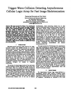
Fig. 2. Single channel circuit details including Q adjustment by local DAC and HWR circuit. Cascodes in mirrors and differential pairs are omitted. req and req are the request signals to the AER communication circuit from each PFM. ack and ack are the acknowledge signals. The integration node, , of the PFM is , the AND of the acknowledge signals from the AER circuits. reset by
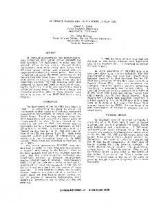
Fig. 3. Second-order section filter. Transistor W/L are 3.2 um/1.8 um.
currents vary exponentially along the filter cascade by taking from a resistive ladder biased at both ends such that the higher bias current (corresponding to higher cutoff frequency) is at the input end. The exponential variation of along the
filter cascade implements the approximate logarithmic dependence of the preferred frequency selectivity with position along the basilar membrane of the biological cochlea. Through a differential pair, a fraction of the current can be diverted so that it is the bias current of the feedback amplifier. A local digital-to-analog converter (DAC) adjusts the value, and hence the bias current to . A difference readout, V2-V1, of each SOS output drives a half-wave rectifier (HWR) circuit, and the HWR output, IIHC1:4, drives 4 PFMs with individual global thresholds (VT1 to VT4), allowing volume encoding by selective activation of PFMs. Each PFM has its own AER address. Compared with regularly-sampled audio systems, the PFM outputs are transmitted asynchronously, which reduces latency down to the delay along the filter bank and increases temporal resolution to microseconds. The group delay is approximately 30 ms from the starting filter (CF around 20 kHz) in the cascade to the last filter (CF around 100 Hz). The maximum PFM event rate is set by a bias that determines the refractory period of the PFMs. During the refractory period following a pulse the PFM discards input current. This bias is set so that approximately 1 spike per cycle is generated by the highest frequency channel. Each stage includes a kill-bit latch which stores a bit that suppresses its PFM output. This feature allows for the suppression of channels with high background PFM rates or for reducing the number of channels that transmit output events. The application of the latter helps to limit the post processing to the channels of interest. In the measurements presented in this paper, the kill bits are not used to suppress any channels.
456
IEEE TRANSACTIONS ON BIOMEDICAL CIRCUITS AND SYSTEMS, VOL. 8, NO. 4, AUGUST 2014
The difference output of a single SOS (which is also the input to its HWR circuit) is the difference of the outputs of the forward transconductance amplifiers and
(1) where is the complex frequency, , and and are the transconductances of amplifiers and respectively. This difference readout adds a desirable zero to the transfer function without introducing undesirable gain proportional to frequency, as would occur with a temporal high pass filter [24]. It sharpens the filter response to approximate closer a band-pass response and reduces the phase accumulation across the cascade. The half-wave rectifier circuit is a simplified model of the response of the inner hair cells (IHCs) of the biological cochlea. The output of this circuit to first approximation is given by
(2) where is controlled by , and is a DC current that can be set to bias a steady PFM output frequency. The linear range of the HWR is increased by using diode-degenerated transistors and mismatch was reduced by using CLBTs as in the SOS stage shown in Fig. 3. This HWR circuit was chosen because of its simplicity and the constraint of the HWR layout area to fit the number of channels for each cochlea within a desired chip area. Although this rectifier is functional, it does not rectify small signals very well and introduces a considerable amount of current-mirror mismatch when generating to the PFM circuit. Future versions of the cochlea will use a rectifier with higher-performance rectification of small signals [6]. The mirrored current drives 4 PFM circuits, each implemented as an integrate-and-fire neuron model but with their own individual threshold (VT) [25]. The number of events created in a cycle is set by the amplitude and frequency of the input, and the amount of charge needed to generate an event. The latter is set by the capacitor in the neuron circuit and the threshold voltage, VT. The charge input onto within a single half cycle of a sinusoidal input with amplitude and period is approximately given by
(3) Thus the number of events generated per second, r, is given by , so r is proportional to the amplitude of BM activity but does not depend on frequency. The 4 PFM circuits can be set with different VT’s so that the PFM circuit with the higher VT will produce an output only for higher values compared to the one with the lowest VT. The output rate of the PFM can also be limited by a refractory
bias. This feature is useful when the output rate of the cochlea is high due to multiple channels firing at the same time. The multiple PFM circuits emulate the multiple spiral ganglion cells with different firing thresholds driven by a single IHC in the biological cochlea. B. Q Adjustment Circuits To control the Q of each filter individually and to provide top-down control of the Qs of specific filter channels, a local Q-adjustment digital-to-analog converter (QDAC) is incorporated within each stage. The ratio of the bias currents of the forward and feedback amplifiers, and , in the SOS stage of each filter sets the Q of the filter. The effective gain of the output of each section, when embedded in the cascade, is larger than the maximum gain of a single section, because the resonances of neighboring sections, where their gain is larger than one, overlap. The gain will increase for the first few sections in the cochlea, after which it settles to a constant maximum value, which is a function of the Q of the individual sections and the number of sections per octave of preferred frequency. The local bias current is derived from a current splitter controlled by 5 bits. The current splitter comes from the bias generator circuits used on many neuromorphic chips [26]. A voltage is generated from the output DAC current using a diode-connected transistor. The value determines the bias current of the feedback amplifier. C. N’th Transfer Function of the n’th stage in the cascaded architecThe output ture is described by (4)
where is the time constant of the i’th stage and is dependent on the bias from the resistive ladder in Fig. 3; and is the input to the first SOS of the cascade. The assumption in (4) is that all stages have identical Q. III. IMPLEMENTATION The AEREAR2 chip (Fig. 4) was fabricated in a 0.35 um 2P4M CMOS process. The PFM output addresses are transmitted asynchronously off-chip using the AER protocol [27]. A bus-powered USB board based on [23], [28] with integrated microphones (Fig. 4) interfaces to a PC running jAER, an opensource software project for the real-time processing of AER sensor output [19]. The USB interface time-stamps the events with a 1 us resolution. The time-stamped events are sent to a PC where they are processed for applications. For natural sounds, the on-chip microphone preamplifiers were used. Additionally for analysis of channel responses, input was applied from a PC sound card directly to the filter cascade (i.e., bypassing the preamplifiers). Off-chip ADCs (Analog Devices AD7933) digitize various signals for characterization: the microphone inputs to the chip, the scanned outputs of the basilar membrane and the
LIU et al.: ASYNCHRONOUS BINAURAL SPATIAL AUDITION SENSOR WITH 2
64
4 CHANNEL OUTPUT
457
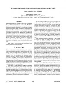
Fig. 5. Response to spoken sentence “Which tea party did Baker go to?” (a) Events from right (red) and left (green) PFM outputs. (b) Sampled audio from right microphone preamplifier output.
Fig. 4. Die photograph and prototype USB board.
neuron potentials of the PFM circuits, which are accessed by the shift register labeled Scanner in the die photograph. IV. MEASUREMENT RESULTS In contrast to most prior work, the results in this paper primarily report measurements from the final digital PFM outputs of the chip rather than from intermediate signals. Fig. 5 shows event rasters and the analog input sound waveform in response to a spoken sentence at a distance of 1 m from the PCB at normal speech volume (65 dB LAF SPL as measured with a Bruel & Kjaer 2250). The background noise level consisting of a nearby computer with a noisy fan was at 45 dB LAF SPL. The on-chip preamplifiers were used for this measurement at the setting (Fig. 6). In Fig. 5(a), each dot represents one event; here the events from the two cochleas are shown in different colors. The sentence was intentionally spoken as isolated words to make it easier to see the structure. Vowel phonemes such as “ah” and “ee” and “oo” are distinguishable and repeatable by inspection as well as fricatives such as “ch” and “t”. Certain channels are more excitable than others and have background activity leading to a sustained background event rate of about 4 keps. The mean event rate is 80 keps with a peak event rate of about 325 keps. The sampled microphone output as recorded through the on-board ADC is displayed in Fig. 5(b). The on-chip microphone preamplifier based on [20] includes 4 levels of gain setting, implemented by digital selection of the feedback resistance as shown in the preamplifier circuit in is connected to a standard Fig. 6(a). The preamplifier input
Fig. 6. (a) Integrated microphone preamplifier. (b) Relative acoustic frequency responses. Each curve shows gain of preamplifier relative to lowest gain setting.
electret microphone capsule, which includes an integrated JFET J1, as illustrated. The DC microphone current is supplied by the large on-chip transistor M2. The small-signal variations in JFET current flow across the feedback resistance , which can be varied from 80 k to 8 80 k . The preamplifier holds its at the virtual ground . The transconductance input
458
IEEE TRANSACTIONS ON BIOMEDICAL CIRCUITS AND SYSTEMS, VOL. 8, NO. 4, AUGUST 2014
Fig. 7. Chirp response. Event rasters recorded from the 64 channels of both cochleas as the frequency of the input is logarithmically swept from 15 Hz to 10 kHz with an amplitude of 600 mV .
amplifier nOTA servos so that M2 supplies and the nOTA transconductance determines the corner frequency. To measure the microphone preamplifier response characteristics, we use an SR780 spectrum analyzer to record swept-sine frequency responses at the preamplifier output in response to sinusoidal sound played from a JBL Professional speaker at a distance of 1 m from the cochlea PCB. We also measured the response using the Bruel & Kjaer reference microphone at a point which is a few cm from the AEREAR2 microphone. At a driving amplitude of 100 mVpp, the resulting sound volume at the cochlea PCB is 60 dB LAF SPL which produces a preamplifier output amplitude of 50 mVpp at 1 kHz with the setting. An anechoic chamber was not available for measuring the preamplifier auditory transfer functions; as a result, there were a number of peaks and dips of up to 30 dB in the recorded frequency responses due to reflections from the lab bench and the AEREAR2 PCB. We first computed the ratio of the AEREAR2 preamplifier response to the Bruel & Kjaer microphone response. The frequency response curves in Fig. 6(b) show the ratio of this relative response to the relative response at the lowest gain setting. Gain settings of 2, 4 and 8 result in expected 6 dB differences in gain. The corner frequency is controlled by the preamplifier feedback OTA transconductance bias current and was set to about 300 Hz. The high-frequency cutoff is set by the forward amplifier bias currents to be at about 20 kHz, but the sharper cutoff as illustrated in Fig. 6(b) comes from the additional speaker cutoff. The peaking in the response that increases at higher gain settings is probably a measurement artifact caused by increased SNR in the measurement of the acoustic response at higher amplitude output. Characteristics of the final AEREAR2 PFM outputs are revealed by using a chirp frequency sweep as an input. Fig. 7 shows the raw PFM outputs of the 64 channels of the two cochleas in response to a chirp frequency-sweep with 600 mV amplitude at the filter cascade input. All channels respond to only a limited frequency range of the chirp. At any one frequency, about 15 channels respond to this large
Fig. 8. PFM frequency and amplitude responses of three channels. Each curve represents the event-rate response versus sinusoidal input frequency for different input amplitudes of 200 mV to 1200 mV in steps of 200 mV.
amplitude input. At 15 Hz, for example, there is a burst of five events during each rising edge of the input. The peak event rate is similar over all channels because as explained in Section II.A the PFM circuit requires a fixed amount of charge to generate each event and at higher frequencies each event requires more cycles. The amplitude and frequency response characteristics are also revealed by varying sound volume. Fig. 8 shows measurements of frequency responses of three widely-separated channels for six different sound volumes. Frequency responses broaden with volume as more PFMs go above threshold, but the upper cut-off frequencies and roll-off slopes do not change. This effect also causes a small change in the characteristic frequency (CF) as a function of input amplitude. For spatial audition, it is important that corresponding channels from the two cochleas are matched. Fig. 9 shows the CF, the number of events per second, and the measured Q values extracted from one of the four PFM outputs of each channel of both cochleas. The CFs (Fig. 9(a)) are logarithmically distributed over the 64 channels and for the 60 of 64 channels where both cochleas respond to the 340 mV input the CFs are matched to % between the two cochleas at corresponding channels. The event rate (Fig. 9(b)) varies substantially due to mismatch in both the PFM and half-wave rectifier circuits but because of the constant Q across the filters and the difference readout scheme of the SOS, the mean of the event rate is approximately constant along the filter cascade. The Qs (Fig. 9(c)) are computed as (CF/width at 0.7 of response at the CF) and are matched between cochleas to %. The event rate and Q matching are poorer than the CF matching because they are more sensitive to the “iceberg” effect of HWR output variation or PFM neuron threshold. A channel with a smaller HWR output or a higher neuron threshold will produce an artificially high Q value because it will respond only over a small range of frequencies. We discuss how these non-idealities can be improved in the conclusion.
LIU et al.: ASYNCHRONOUS BINAURAL SPATIAL AUDITION SENSOR WITH 2
Fig. 9. Measured characteristics from PFM output #1 at input amplitude of 270 mVpp. (a) Extracted binaural CFs for left and right cochleas. (b) Event rate at each channel. (c) Extracted Q values at each channel.
A. Frequency Extraction Although the tuning of the filters is relatively broad as is observed in biological cochleas, the frequency of the input signal can be extracted with very high precision from the PFM outputs of the channels. Fig. 10(a) shows the PFM outputs for an input of a particular frequency. The recorded inter-pulse PFM intervals are first pre-processed by imposing a refractory period in software so that multiple events within a single half-cycle which lead to small PFM intervals are removed. By histogramming the time intervals between the processed events and locating the peak value of the histogram, we can measure the input frequency. Fig. 10(b) shows the extracted input frequency using this method from a range of input frequencies. Using this method, the input frequency can be extracted to the precision of the event timing jitter. The measured jitter using a sinusoidal input of 250 mVpp is less than 2 us at 1 kHz, therefore the input frequency can be measured to a precision of better than 0.2% error at 1 kHz from single event intervals, and the error is reduced as additional events are accumulated. In the biological cochlea, the extraction of the frequency is not possible at high frequencies because phase locking breaks down above approximately 3 kHz [2]. In the AEREAR2, the highest input frequency
64
4 CHANNEL OUTPUT
459
Fig. 10. Extracting input frequency from event timing. (a) Example of PFM ouputs for a single input frequency of 1.7 kHz. Each channel is phase locked to the input but with different phase. (b) Measured period from PFM outputs versus period of input frequency. Input frequencies played from 100 Hz to 5.88 kHz with input amplitude of 250 mVpp. The measured period is extracted from the peak location of histogram of the processed event intervals.
which can be extracted is dependent on the setting of the refractory period of the neuron. B. Digital Q Adjustment As described in Section II.B, the Qs of the PFM outputs can be adjusted through the local QDAC. Fig. 11(a) shows the effect of the QDAC code on the analog SOS output (described in Section II.C) of a single channel. Decreasing the QDAC code increases the channel gain of the analog SOS output. The Q difference between and 23 is about 6.7% with for . The Q increase is small because of the limited linear input range of the amplifiers. Fig. 11(b) shows that a local reduction of gain can be produced by only changing the QDAC value in a part of the filter cascade. The plot shows the ratio (after/before) of the maximum PFM output rate from each channel. Here the QDAC code is changed in sections 35 to 40 to reduce the gain, resulting in fewer events from these stages. The event rate of stages downstream (41–45) are also affected because of the cascaded architecture. This influence is limited by the rising part of the filter response of a channel, its particular best frequency, and the minimum response needed to generate a PFM output. Fig. 11(c) shows the opposite, that the gain of stages 50 to 60 is increased by decreasing the QDAC code
460
IEEE TRANSACTIONS ON BIOMEDICAL CIRCUITS AND SYSTEMS, VOL. 8, NO. 4, AUGUST 2014
Fig. 12. Event-based correlation algorithm histogram results for interaural time delay (ITD) for recorded speech. Response is based on a sound mixture of two frequencies. Each column represents one histogram and dark values represent a large correlation. (Reanalyzed for finer ITD resolution from data in Fig. 4 in [14].)
C. Localization Application
Fig. 11. Effect of QDAC. (a) The effect of QDAC on the analog output of a single SOS within the cascade. Decreasing QDAC code value mainly increases the channel gain (by 7 dB) and slightly increases Q. (b) Locally decreasing gain in channels by changing QDAC. Decrease in gain of channels 35 to 40 when the to . The plot shows the ratio code is changed from of event rate (after/before) by this local change. Measurements are done with a swept sine input at an amplitude of 600 mV . (c) Same as in (b) but here the gain for the low frequency channels from 50 to 60 is increased.
in these channels. Because the responses after the change of QDAC are larger, channel mismatch causes the change in the responses to be more variable. Because of the cascade structure, the cochlea response is affected for stages within and downstream from the modified channels. Thus the QDAC can be used to locally control cochlea frequency response, mainly by controlling the gain.
The event-based AEREAR2 system is presently being used in a variety of applications [29]–[32]. In this section, we describe one of these (i.e., sound localization) as an example. In the method used here, sound localization is based on interaural time difference (ITD) and is conventionally done by applying generalized cross-correlation methods on the sampled outputs of binaural microphones [33]. These methods use various prewhitening filters on the input signals before estimating the delay between the two signals [34]. From the binaural PFM outputs of the AEREAR2, an eventbased localization algorithm was proposed in [14]. In this work, the authors show that the spatial resolution based on the ITD information in the PFM AEREAR2 events can be inferred with a mean error of less than 1 degree (corresponding to a temporal resolution of 6 us). This resolution is comparable to that obtained using generalized cross-correlation methods based on the raw microphone outputs sampled at a rate of 100 kHz. In the case of the event-based algorithm, correlations are performed on each event, by matching it to the past few events in a time window of 1 ms (corresponding to the maximum possible delay) from the corresponding channel in the other ear. These possible matches are accumulated in time-decaying histograms, and the possible ITDs of sources are inferred from the peaks of the ITD histogram. The ITD extracted from a single pairing of events from the left and right ears can be weighted depending on the silent period prior to the paired events and this weighting suppresses false ITDs caused by reflected sound, because the direct sound is weighted more heavily. Fig. 12 shows these weighted ITD histograms as a function of the played ITD for speech input. For each played ITD, the peak of the ITD histogram follows the played ITD. The eventbased approach is advantageous over the conventional methods for several reasons. First, it requires few computational operations because of the event-driven form of the input events (i.e., correlations are not performed unless there is an input sound).
LIU et al.: ASYNCHRONOUS BINAURAL SPATIAL AUDITION SENSOR WITH 2
Fig. 13. Mean latencies in the estimated ITD after the speaker location changes. The latency depends mainly on the histogram decay time constant (128 ms) but is reduced slightly by a higher weighting of sound onsets. (Adapted from Fig. 6 in [14].)
Second, sounds onsets are most important to consider in localization because they represent direct rather than reflected paths and with event-driven processing sound onsets can be easily weighed more strongly, simply by weighting an ITD by the length of silence before the event. Third, the estimate of the location is fast; usually with 100 events a good estimate is already obtained. Fig. 13 shows that new speaker locations are detected with latencies of about 170 ms even with histogram decay time constant ms. As onsets are weighted more strongly, latency is still further decreased. D. Comparison Between Event-Based and Conventional Sound Localization Algorithms Although digital solutions are typically favored in audio applications, the proper combination of analog and digital processing following the microphone front end can offer advantages in both power dissipation and computational cost [35]–[38]. Digital solutions usually comprise a front-end ADC that samples the audio signal at tens or hundreds of kHz with 16 (or more) bits of precision. The samples are then processed by a digital signal processor (DSP). However, not all applications require the information carried by the high amplitude precision of the sampled values. For example, only precise phase timing in the input frequencies is needed for music appreciation in cochlear implant patients [35]. The cochlear implant processor by Sit and Sarpeshkar, for example, produces asynchronous outputs which encode the zero-crossings of the outputs for each of the 16 channels, thus preserving phase timing of the signals. In this design, the authors argued that they were able to design a much lower power dissipation processor (357 uW) than the 5 mW dissipation power of a digital system which includes both ADC and DSP. The main computational advantage of the AEREAR2 is that the sensor only outputs data in response to sound energy at its input. But event-based algorithms like the event-based localization algorithm described in Section V can also be computationally cheaper than conventional algorithms that use sampled inputs because computation is driven by signal activity. To see this, we will assume that the AEREAR2 produces data at a fixed
64
4 CHANNEL OUTPUT
461
rate in response to speech and compute the number of operations needed for localization using the cross-correlation of the sampled outputs of two microphones and compare this number to that used by the event-based localization algorithm. For regular sampling, cross correlation is performed by fast Fourier transform (FFT) on each microphone input, followed by FFT multiplication across inputs, followed by inverse FFT (IFFT). To determine the number of operations, we assume a desired resolution of 10 us, and we assume an FFT operation of 128 samples of an audio signal sampled at 44.1 kHz. Then we will need an FFT every 2.9 ms or 344 FFTs per second for each input of the 2 ears. Each FFT has a cost of about 3 k arithmetic operations (op). We can neglect the small operational cost of the cross multiplication of FFTs. We then compute the number of operations needed for the IFFT. We perform the IFFT at 200 kHz, to provide 10 us resolution on the cross correlation. Thus each IFFT has a cost of approximately 12 kop. The total cost is thus Mops operations per second (ops). The AEREAR2 system produces an average PFM rate of 20 keps under normal speech conditions at a distance of several meters. For each PFM event from one ear, there is an average of three pairings of ITD events with the opposite ear, leading to 60 kops. We have to consider in addition, the number of operations to decay the histogram. There are 140 bins for a 10 us resolution over us. Decaying the histogram every 2.9 ms requires 100 kops, although in practice this decay can be done at a much lower rate defined by the desired latency. The total cost is about 150 kops. Thus the event-driven method is about times computationally cheaper than the sampled method. We have left out for the sampled approach the cost of pre-whitening the input signals. The event-based approach is easily computed in fixed point arithmetic while FFTs are sensitive to round off errors. V. CONCLUSION Table I compares design features and specifications to prior work. Compared with prior work, results from this work are presented based on measurements from final PFM digital output. This cochlea provides binaural operation, integrated biasing, integrated microphone preamplifiers, USB2.0 high-speed interface, and open-source host side software. It achieves usable dynamic range of 52 dB when combined with a preamplifier with adjustable gain, and a power consumption of 14 mW. Dynamic range is currently limited by the amount of basilar membrane voltage signal required to generate PFM events and could be improved by increasing preamplifier gain or decreasing neuron threshold. Across-ear matching of CF % and Q % is satisfactory for spatial audition tasks as demonstrated by application studies but cannot be compared with other designs which do not report these values. The AEREAR2 includes on-chip channel adjustment for controlling spectral selectivity in cascaded filter bank designs, where they are particularly valuable. It also achieves usable matching between corresponding channels from the left and right ears, which is important for spatial audition. The integration of on-chip per-channel Q adjustment and user-friendly USB implementation is useful in future work on application
462
IEEE TRANSACTIONS ON BIOMEDICAL CIRCUITS AND SYSTEMS, VOL. 8, NO. 4, AUGUST 2014
TABLE I SPECIFICATION COMPARISON OF AER COCHLEAS
scenarios. Using the local QDAC, the implementation of a real-time feedback loop which adjusts the local Q based on the local signal levels can be developed in the future. The application of the AEREAR2 in a localization task was also described. Processing is done on the asynchronous PFM events rather than on spectrograms generated from sampled raw audio inputs. In a scenario where the AEREAR2 generates output continuously at a rate of 20 keps, the computational cost associated with the event-driven form of the cochlear outputs suggest a 40x lower computational cost for post-processing algorithms compared with conventional cross correlation methods, as outlined in Section IV.D. The sensor design can be further improved. At present, because the implemented QDAC circuit uses the large master current at each stage it consumes at least 30% of the analog power. Simple redesign of this circuit will reduce the power consumption significantly. Although the present design is suitable for normal speech volume at distances of 5 m, increasing the range of on-chip preamplifer gain values and improved HWR and PFM circuits will lead to direct improvements of dynamic range for softer environmental sounds. The large-signal transfer function of the microphone pre-amplifier is not ideal. We have iden-
tified it is due to the non-ideality of the feedback nOTA, and we are working on an improved version for the future. Inclusion of a low-resolution DAC for calibrating the output of the half-wave rectifier circuit which drives the PFM circuit will improve sensitivity and uniformity. The addition of local gain control circuits will implement closer the functionality of the biological cochlea as explored in [39], [40]. Because of the novel asynchronous output representation and the user-friendly implementation of this cochlea, we can begin exploring event-based digital signal processing algorithms for application in auditory tasks such as spatial audition [10], [13], [14], speaker identification [29], [30], [32], [33], isolated digit recognition [31], and in multi-sensor fusion.
ACKNOWLEDGMENT The authors thank R. Berner for assistance in the CPLD firmware on the cochlea system, F. Blaettler for the computational cost discussions, and H. Finger for the work in the frequency response measurement software in jAER.
LIU et al.: ASYNCHRONOUS BINAURAL SPATIAL AUDITION SENSOR WITH 2
REFERENCES [1] S. Shamma, “Speech processing in the auditory system I: The representation of speech sounds in the responses of the auditory nerve,” J. Acoust. Soc. Amer., vol. 78, pp. 1612–1621, 1985. [2] A. R. Palmer and I. J. Russell, “Phase-locking in the cochlear nerve of the guinea-pig and its relation to the receptor potential of inner haircells,” Hear. Res., vol. 24, pp. 1–15, 1986. [3] J. Lazzaro, J. Wawrzynek, M. Mahowald, S. Sivilotti, and D. Gillespie, “Silicon auditory processors as computer peripherals,” IEEE Trans. Neural Netw., vol. 4, pp. 523–528, 1993. [4] N. Kumar, W. Himmelbauer, G. Cauwenberghs, and A. Andreou, “An analog VLSI chip with asynchronous interface for auditory feature extraction,” IEEE Trans. Circuits Syst. II, Analog Digit. Signal Process., vol. 45, pp. 600–606, 1998. [5] B. Wen and K. Boahen, “A 360-channel speech preprocessor that emulates the cochlear amplifier,” in Proc. ISSCC Dig. Tech. Papers, 2006, pp. 556–557. [6] R. Sarpeshkar, C. Salthouse, J. J. Sit, M. Baker, S. Zhak, T. Lu, L. Turicchia, and S. Balster, “An ultra-low-power programmable analog bionic ear processor,” IEEE Trans. Biomed. Eng., vol. 2, pp. 711–727, 2005. [7] E. Fragniere, “A 100-channel analog CMOS auditory filter bank for speech recognition,” in Proc. ISSCC Dig. Tech. Papers, 2005, pp. 140–589. [8] J. Georgiou and C. Toumazou, “A 126-uW cochlear chip for a totally implantable system,” IEEE J. Solid-State Circuits, vol. 40, pp. 430–443, 2005. [9] H. Abdalla and T. K. Horiuchi, “An ultrasonic filterbank with spiking neurons,” in Proc. IEEE Int. Symp. Circuits and Systems, 2005, pp. 4201–4204. [10] V. Chan, S.-C. Liu, and A. van Schaik, “AER EAR: A matched silicon cochlea pair with address event representation interface,” IEEE Trans. Circuits Syst. I, Reg, Papers, vol. 54, pp. 48–59, 2007. [11] S.-C. Liu and T. Delbruck, “Neuromorphic sensory systems,” Current Opin. Neurobiol., vol. 20, pp. 1–8, 2010. [12] H. Abdalla and T. K. Horiuchi, “Binaural spectral cues for ultrasonic localization,” in Proc. IEEE Int. Symp. Circuits and Systems, 2008, pp. 2110–2113. [13] V. Chan, C. Jin, and A. van Schaik, “Adaptive sound localisation with a silicon cochlea pair,” Front. Neurosci., vol. 4, no. 196, 2010. [14] H. Finger and S.-C. Liu, “Estimating the location of a sound source with a spike-timing localization algorithm,” in Proc. IEEE Int. Symp. Circuits and Systems, 2011, pp. 2461–2464. [15] R. F. Lyon and C. Mead, “An analog electronic cochlea,” IEEE Trans. Acoust. Speech Signal Process., vol. 36, pp. 1119–1134, 1988. [16] L. Watts, D. Kerns, R. Lyon, and C. Mead, “Improved implementation of the silicon cochlea,” IEEE J. Solid State Circuits, vol. 27, pp. 692–700, 1992. [17] R. Sarpeshkar, R. F. Lyon, and C. Mead, “A low-power wide-dynamicrange analog VLSI cochlea,” Analog Integr. Circuits Signal Process., vol. 16, pp. 245–274, Aug. 1998. [18] T. Hamilton, C. Jin, A. van Schaik, and J. Tapson, “An active 2-D silicon cochlea,” IEEE Trans. Biomed. Circuits Syst., vol. 2, pp. 30–43, 2008. [19] T. Delbruck, jAER Open Source Project, 2007 [Online]. Available: http://jaerproject.org [20] M. W. Baker and R. Sarpeshkar, “A low-power high-PSRR currentmode microphone preamplifier,” IEEE J. Solid-State Circuits, vol. 38, pp. 1671–1678, 2003. [21] T. Delbruck, T. Koch, R. Berner, and H. Hermansky, “Fully integrated 500 uW speech detection wake-up circuit,” in Proc. IEEE Int. Symp. Circuits and Systems, Paris, France, 2010, pp. 2015–2018. [22] T. Delbruck and P. Lichtsteiner, “Fully programmable bias current generator with 24 bit resolution per bias,” in Proc. IEEE Int. Symp. Circuits and Systems, Athens, Greece, 2006, pp. 2849–2852. [23] S.-C. Liu, A. van Schaik, B. Minch, and T. Delbrück, “Event-based 64-channel binaural silicon cochlea with Q enhancement mechanisms,” in Proc. IEEE Int. Symp. Circuits and Systems, 2010, pp. 2027–2030. [24] A. van Schaik, E. Fragnière, and E. Vittoz, “Improved silicon cochlea using compatible lateral bipolar transistors,” in Proc. Advances in Neural Information Processing Systems 8, 1996, pp. 671–677. [25] C. Mead, Analog VLSI and Neural Systems. Reading, MA, USA: Addison-Wesley, 1989. [26] T. Delbrück and A. van Schaik, “Bias current generators with wide dynamic range,” Analog Integr. Circuits Signal Process., vol. 43, pp. 247–268, 2005.
64
4 CHANNEL OUTPUT
463
[27] K. A. Boahen, “A burst-mode word-serial address-event link-I transmitter design,” IEEE Trans. Circuits and Syst. I, Reg. Papers, vol. 51, pp. 1269–1280, 2004. [28] R. Berner, T. Delbrück, A. Civit-Balcells, and A. Linares-Barranco, “A 5 Meps $100 USB2.0 address-event monitor-sequencer interface,” in Proc. IEEE Int. Symp. Circuits and Systems, 2007, pp. 2451–2454. [29] S. Chakrabartty and S.-C. Liu, “Exploiting spike-based dynamics in a silicon cochlea for speaker identification,” in Proc. IEEE Int. Symp. Circuits and Systems, 2010, pp. 513–516. [30] S.-C. Liu, N. Mesgarani, J. Harris, and H. Hermansky, “The use of spike-based representations for hardware audition systems,” in Proc. IEEE Int. Symp. Circuits and Systems, 2010, pp. 505–508. [31] M. Abdollahi and S.-C. Liu, “Speaker-independent isolated digit recognition using an AER silicon cochlea,” in Proc. Biomedical Circuits and Systems Conf., 2011, pp. 269–272. [32] C.-H. Li, T. Delbruck, and S.-C. Liu, “Real-time speaker identification using the AEREAR2 event-based silicon cochlea,” in Proc. IEEE Int. Symp. Circuits and Systems, 2012, pp. 1159–1162. [33] J. Voordouw, Z. Yang, L. Rothkrantz, and C. van der Mast, “A comparison of the ILD and TDOA sound source localization algorithms in a train environment,” Euromedia, pp. 61–68, 2007. [34] C. Knapp and G. Carter, “The generalized correlation method for estimation of time delay,” IEEE Trans. Acoust. Speech Signal Process., vol. 24, no. 4, pp. 320–327, 1976. [35] J. Sit and R. Sarpeshkar, “A cochlear-implant processor for encoding music and lowering stimulation power,” IEEE Pervasive Comput. (Special Issue, Implantable Electronics), vol. 1, pp. 40–48, 2008. [36] R. Sarpeshkar, “Analog versus digital: Extrapolating from electronics to meurobiology,” Neural Comput., vol. 10, pp. 1601–1638, 1998. [37] P. Hasler and D. V. Anderson, “Cooperative analog-digital signal processing,” in Proc. IEEE Int. Conf. Acoustics, Speech, and Signal Processing, 2002, vol. 4, pp. IV-3972–IV-3976. [38] S. Mandal, S. M. Zhak, and R. Sarpeshkar, “A bio-inspired active radio frequency silicon cochlea,” IEEE J. Solid-State Circuits, vol. 44, no. 6, pp. 1814–1828, 2009. [39] B. Wen and K. Boahen, “A silicon cochlea with active coupling,” IEEE Trans. Biomed. Circuits Syst., vol. 3, pp. 444–455, 2009. [40] A. Katsiamis, E. Drakakis, and R. Lyon, “A 4.5 uW, 120 dB, logdomain cochlea channel with AGC,” IEEE J. Solid-State Circuits, vol. 44, pp. 1006–1022, 2009.
Shih-Chii Liu (M’02–SM’07) studied electrical engineering as an undergraduate and received the Ph.D. degree in the Computation and Neural Systems program from the California Institute of Technology, Pasadena, CA, USA, in 1997. She worked at various companies including Gould American Microsystems, LSI Logic, and Rockwell International Research Labs. She is currently an Oberassistentin at the Institute of Neuroinformatics, University of Zurich and ETH Zurich, Zurich, Switzerland. Her current research interests include neuromorphic visual and auditory sensors, cortical processing circuits, and event-based circuits and algorithms. Dr. Liu is past Chair of the IEEE CAS Sensory Systems and Neural Systems and Applications Technical Committees. She is currently Chair of the IEEE Swiss CAS Society and an associate editor of the IEEE TRANSACTIONS ON BIOMEDICAL CIRCUITS AND SYSTEMS and Neural Networks.
André van Schaik (M’00–SM’02) received the M.Sc. degree in electrical engineering from the University of Twente, Enschede, The Netherlands, and the Ph.D. degree in electrical engineering from the Swiss Federal Institute of Technology (EPFL), Lausanne, Switzerland, in 1990 and 1998, respectively. Currently, he is a Professor of Bioelectronics and Neuroscience in the MARCS Institute at the University of Western Sydney, Australia. His research focuses on three main areas: neuromorphic engineering, bioelectronics, and neuroscience. He has authored more than 100 papers and is an inventor of more than 30 patents. He is a Founder of three startup companies: VAST Audio, Personal Audio, and Heard Systems.
464
IEEE TRANSACTIONS ON BIOMEDICAL CIRCUITS AND SYSTEMS, VOL. 8, NO. 4, AUGUST 2014
Bradley A. Minch (M’97) received the B.S. degree (with distinction) in electrical engineering from Cornell University, Ithaca, NY, USA, and the Ph.D. degree in computation and neural systems from the California Institute of Technology, Pasadena, CA, USA, in 1991 and 1997, respectively. Currently, he is Professor of Electrical and Computer Engineering at the Franklin W. Olin College of Engineering, Needham, MA, USA. From 2004 to 2009, he was Associate Professor of Electrical and Computer Engineering at Olin College. From 1997 to 2004, he was an Assistant Professor in the School of Electrical and Computer Engineering at Cornell University. His research interests include lowvoltage/low-power analog and digital integrated-circuit design, translinear circuits, log-domain filters, and adaptive floating-gate metal-oxide semiconductor circuits. Dr. Minch received the IEEE Electron Devices Society’s Paul Rappaport Award in 1996. He received a CAREER award from the National Science Foundation in 2000. He is a member of the Tau Beta Pi, Eta Kappa Nu, and Phi Kappa Phi honor societies.
Tobi Delbruck (M’99–SM’06) received the B.Sc. degree in physics and applied mathematics from the University of California, San Diego, La Jolla, CA, USA, and the Ph.D. degree from the California Institute of Technology, Pasadena, CA, USA, in 1986 and 1993, respectively. Currently, he is a Professor of Physics at ETH Zurich in the Institute of Neuroinformatics, University of Zurich and ETH Zurich, Zurich, Switzerland, where he has been since 1998. His group focuses on neuromorphic sensory processing. He worked on electronic imaging at Arithmos, Synaptics, National Semiconductor, and Foveon. He has co-organized the Telluride Neuromorphic Cognition Engineering summer workshop and the live demonstration sessions at ISCAS. Dr. Delbruck is past Chair of the IEEE CAS Sensory Systems Technical Committee, current Secretary of the IEEE Swiss CAS Society, and an associate editor of the IEEE TRANSACTIONS OF BIOMEDICAL CIRCUITS AND SYSTEMS. He has been awarded nine awards by the IEEE.