Dec 13, 2007 - The data model for event reconstruction (EDM) in the Inner Detector of the ..... dard Template pair containing the IdentifierHashes of the two ...
ATLAS Inner Detector Event Data Model F. Akesson1, M.J. Costa2, D. Dobos1 , M. Elsing1, S. Fleischmann3, A. Gaponenko4, K. Gnanvo5, P.T. Keener6 , W. Liebig7,∗, E. Moyse8, A. Salzburger1,9, M. Siebel1, A. Wildauer1
Abstract
13 December 2007
ATL-SOFT-PUB-2007-006
12th December 2007
The data model for event reconstruction (EDM) in the Inner Detector of the ATLAS experiment is presented. Different data classes represent evolving stages in the reconstruction data flow, and specific derived classes exist for the sub-detectors. The Inner Detector EDM also extends the data model for common tracking in ATLAS and is integrated into the modular design of the ATLAS high-level trigger and off-line software.
1
CERN, PH department, Geneva, Switzerland IFIC, Universidad de Valencia - CSIC, Spain 3 Physikalisches Institut, Universit¨ at Bonn, Germany 4 Lawrence Berkeley National Laboratory, Berkeley, USA 5 Dept. of Physics, Queen Mary, University of London, UK 6 Dept. of Physics & Astronomy, University of Pennsylvania, Philadelphia, USA 7 NIKHEF, Amsterdam, the Netherlands 8 Dept. of Physics and Astronomy, University of Massachusetts, Amherst, USA 9 Leopold-Franzens-Universit¨ at Innsbruck, Austria ∗ Corresponding editor: Wolfgang.Liebig @ cern.ch 2
1
Introduction
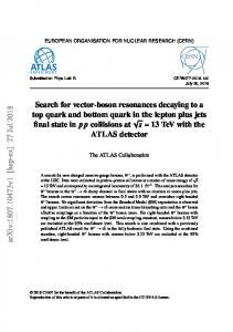
For large collaborations like the ATLAS experiment common data objects and modular algorithms have been designed to ensure easy maintenance and coherence of the experiment’s software platform over a long period of time. The ATLAS EDM improves commonality across all tracking detector subsystems in the inner detector and muon spectrometer. Following the proposals in [1, 2] it has been designed to suit the needs of the high-level trigger, offline track reconstruction, and combined event reconstruction. In addition it was given enough flexibility to allow reconstruction of other data than LHC collisions, for example test-beam and cosmic ray tracks. In practice an object oriented approach has been chosen for the description of the detector data, designed to have one common data flow for all of the above applications and all tracking detectors in ATLAS. This commonality is mainly achieved by formalising the access to data which is present in a similar form in every sub-detector, such as the mathematical representation of measurements, geometry information and handles to access objects from earlier reconstruction stages. The ATLAS inner detector consists of the Pixel detector, the semi-conducting tracker (SCT), and the transition radiation tracker (TRT) [3]. The data flow in the reconstruction is sketched in Fig. 1 and can be summarised as follows. The data acquisition delivers the readout from every sub-detector in form of a byte stream. This byte stream is subsequently converted into data objects by the byte stream converters. The raw data objects are prepared for the track finding by forming clusters, drift circles and space points using information from the detector positions and calibrations. The next step is the track finding and track fitting, during which further calibration corrections to the position and measurement error are applied. The output objects are the final measurements-on-track, which are held by the track objects from the Tracking EDM [4]. A post-processing of those tracks leads to the physics-level description of the measured charged particles and their associated production vertices. The goal of the inner detector EDM is to ensure simple and uniform interfaces between the processing stages of the data and between the reconstruction tools which implement the reconstruction in a modular design. The classes described in this document correspond to the ATLAS offline software release 13.0.30 Byte Stream Conversion
Trackfinding and Fitting
Preparation
Postprocessing
Tools
Services
Figure 1: The schematic inner detector data flow.
1.1
Tracking Information from the Inner Detector
Pixel detector, SCT and TRT employ different charged particle detection techniques and therefore differ in the data they provide. 2
• The Pixel detector is arranged in cylindrical layers and disks fitted with silicon sensors. Each sensor is subdivided into pixels and hence provides a two-dimensional hit position on the module. Together with the surface constraint the Pixel detector provides fully three-dimensional space points. In addition, a time-over-threshold information is read out which is proportional to the deposited charge. A matrix of two by 8 read-out chips are connected directly to the back face of the sensor module. To avoid dead regions, pixels not covered by the readout chips are ganged together electrically with near-by pixels, creating an ambiguity. • The SCT is a similar arrangement of silicon modules, but its sensors are divided into strips and each module consists of two sensor planes glued together back-toback with 1 mm distance. In the barrel the strips are parallel while in the end-cap modules have radially oriented strips. Consequently the measurement provided by a single sensor constrains only one of the two local position coordinates. A small stereo angle of 40 mrad between the two sensor planes provides sensitivity to the position along direction of the strips. Unlike the Pixel detector, the SCT does not provide a charge deposit measurement. • The TRT is an arrangement of small drift tubes of 4mm diameter, its genuine measurement is therefore a drift radius. Once the direction of the particle is known, this drift radius translates into a closest distance to the wire with an ambiguity (which side of the wire the particle passed by). Since the full measurement frame is not defined without a track direction, the measurements are expressed on a line surface associated to each wire. The amount of transition radiation is connected to the type of particle passing through the TRT; the TRT therefore reports additional information such as the time over threshold and a second, high-level discriminator signal.
1.2
From Raw Data to Event Data
The differences in the way how the sub-detectors measure hit position information makes it necessary to store the data in different objects – or at least different child classes of one common object. In addition the subsequent reconstruction levels change the meaning and content of the measurement information by combining and calibrating measurements and associating them to tracks. Different classes are therefore provided also for each of those stages. An inner-detector specific design is chosen for the first stage, the InDetRawData objects (RDO). They are an object version of byte steam data as coming from the DAQ ReadOut Drivers (RODs). The raw data model is described in detail in Section 2.1. There is a difference between LVL2 and Event Filter/Offline in the processing chain from byte stream to raw data. In the LVL2 the RDOs are not produced at all, but directly cluster and drift circle objects are constructed, thus saving the RDO creation and access time. The next stage involves tracking input and output objects which derive from base classes shared with the ATLAS muon spectrometer software. This common tracking EDM and the structure of the base classes are described in detail in [4]. Briefly, the idea behind this design is to apply tracking code on hits from both tracking systems and thus reduce code duplication and allow combined fits across the whole ATLAS detector. Measurements in the inner detector, the clusters and drift circles, are described by objects inheriting from PrepRawData. They are created once by the clustering and drift circle creation 3
algorithms and can not be modified later. This ensures that different versions or stages of the tracking can be run without interfering with each other. To correct PrepRawData further using the track candidate’s position and incidence angle, the track finding and fitting algorithms create a different type of object which inherits from a common base class MeasurementBase. This class carries the information from one or several hits, depending on the needs of the track reconstruction code in use. The class representing a single PrepRawData is called RIO OnTrack1 . Objects of type MeasurementBase are assigned to a track by means of object ownership and form part of the reconstruction’s persistent output stream. The concrete implementations of the inner detector tracking classes are described in Sections 2.2 and 2.4. During the last stage of event reconstruction, information from the inner detector and other ATLAS detectors is used to reconstruct tracks, vertices and physics objects. They usually do not need an inner-detector specific object implementation and are hence designed not to be an exclusive part of the inner detector EDM. Where relevant the inner detector instanciation of such ATLAS-wide objects is described.
2
Event Data Model Objects
The commonality in the data model for track measurements from the inner detector and muon spectrometer is established by allowing each subsystem to access and implement the generic information but disallow any link to the specific information of the other system. Technically, the generic structures of the tracking EDM are organised in a separate CVS repository under offline/Tracking, and defined in a separate namespace Trk::. They are documented in detail in ref. [4]. Inner-detector specific objects (including the inner detector implementation of classes derived from the tracking EDM) are hosted by the offline/InnerDetector repository and defined in the InDet:: namespace. No compile-time dependency between inner detector and muon spectrometer or of the tracking EDM on any of the two systems is allowed. From the computing aspect this approach has helped maintaining object type safety and has considerably improved the stability of the software. Although the raw data objects are implemented in a similar way in the inner detector and muon spectrometer, they are the only objects in the track reconstruction data flow which do not need a common base class and therefore do not share one. The inner detector EDM follows the ATLAS policy of providing only minimal algorithmic content, thus making the objects lightweight The detector geometry follows a similar approach of distinguishing between generic and inner-detector specific entities, but is not an integrated part of the inner detector EDM. Here the ATLAS software framework separates strictly between event and nonevent data, the latter being managed by the DetectorStore instead of the transient event store, StoreGate [5]. Detector data classes can nevertheless be accessed from the EDM objects through their pointers to detector elements and surfaces. 1
An early name proposal for the PrepRawData object was ReconstructionInputObject. Its successor in the data flow, RIO OnTrack, still bears witness of this.
4
2.1
Raw Data Objects
The InDetRawData object (RDO) is a data class designed to store the hit information given by the RODs of the different sub-detectors. It represents uncalibrated data and depends on the output of the particular detector technology (Pixels, SCT or TRT). The byte stream converters are responsible for decoding the different ROD event fragments and creating a raw data object for each recorded signal. The result is a Pixel RDO per fired pixel cell, an SCT RDO per consecutive group of strips or individual strips with signal (depending if the ROD is configured to run in condensed or expanded mode), and a TRT RDO for each straw which has been hit. The RDO contains an offline identifier of the corresponding pixel cell, SCT strip or TRT straw. The BS converter uses the so-called cabling service to map the ROD channel numbers to the module part of the hierarchically structured offline identifier [6]. Additional information contained in the byte stream is also stored in the RDO: For the Pixels, a 32-bit word encoding the time the signal was over threshold and for timing studies the Level 1 and bunch crossing identifiers as well as the Level 1 accept in case several bunch crossings are triggered. For the SCT, a 32 bit word contains the information of the number of consecutive strips with signal, the time-bin pattern corresponding to the information recorded in three consecutive bunch crossings and the error type if present. The TRT RDO contains a 75 ns, 24 bit, time digitization of the output of the discriminator in the front end electronics and whether the high threshold was crossed for each of the 25 ns clock cycles. This enables the RDO class to compute the raw drift time and time over threshold. For the case in which the trigger is not synchronized with the detector readout clock, which is the case of test beam and cosmic rays data, the time difference between the trigger and the next clock edge is also stored in the TRT RDO to allow for a drift time correction. Figure 2 shows the structure of the present raw data objects. For Pixels a single concrete implementation is used for all different data types (LHC, cosmic rays and test beam data). This is also the plan for the SCT which is still using SCT1RawData for the case of simulated raw data. For the TRT two different concrete classes will remain: one for the LHC data in which the bunch crossing is synchronized with the readout clock (TRTLoLumRawData) and another one for the random case (TRTTB04RawData). The classes are located in the code repository under InDetRawData [7].
2.2
Clusters and Drift Circles
The RDOs can not be used directly in the reconstruction but have to be “prepared”, that is translated into a position measurement, assigned an error matrix, positioned with respect to the other detectors and checked for bad channels. The PixelCluster, SCT Cluster and TRT DriftCircle classes are the PrepRawData objects of the inner detector. The first two are meant to store the output of the online and offline clusterisation processes. During this process neighbouring silicon hits are joined into clusters (taking into account bad channels and ganged pixels) and the position of the resulting cluster is computed. For the TRT, the drift time is translated into a drift radius making use of the R–t straw calibration. In both cases an error is added to the measured position. The calculated local cluster position or local drift radius is expressed with respect to a measurement surface from the detector geometry, so that the measured position is known also in the global inner detector frame, including alignment corrections. Although the data class holds a two-dimensional 5
InDetRawData const Identifier m_rdoId const unsigned int m_word Identifier identify() const unsigned int getWord() const
PixelRDORawData int getToT() const = 0 int getBCID() const = 0 int getLVL1A()const = 0 int getLVL1ID()const = 0
SCT_RDORawData
TRT_RDORawData
int getGroupSize() const = 0 int getStrip() const = 0
Pixel1RawData
SCT1_RawData
int getToT() int getBCID() const int getLVL1A() const int getLVL1ID() const
int getGroupSize() const int getStrip() const
bool highLevel() const=0 double timeOverThreshold() const=0 int driftTimeBin() const=0
SCT3_RawData float m_errorCondensedHit[20] int getGroupSize() const int getStrip() const int getTimeBin() const int getErrors() const bool OnTime() const bool SyncronizationError() const bool PreambleError() const bool LVL1Error() const bool BCIDError() const bool FormatterError() const bool FirstHitError() const bool SecondHitError() const float *getErrorCondensedHit()
TRT_LoLumRawData ~TRT_LoLumRawData() bool highLevel() const double timeOverThreshold() const int driftTimeBin() const
TRT_TB04_RawData unsigned int m_timeword ~TRT_LoLumRawData() bool highLevel() const double timeOverThreshold() const int driftTimeBin() const unsigned int getTrigType() const
Figure 2: The inner detector classes for raw data objects, the offline representation of byte stream data from the read-out drivers. LocalPosition member, not every measurement is truly two-dimensional. The SCT barrel modules and the TRT provide a one-dimensional measurement with the second coordinate set to the centre of the module, resp. wire. The SCT end-cap modules are special because the radial orientation of the strips inside a module necessitates a rotation from the strip frame to the module frame. The measurement of the second √ co-ordinate in the strip’s frame is assumed to be the strip centre with an error of 1/ 12·strip length. Two dimensions are already given by the Pixels at this level. The class diagram is shown in Figure 3. To exploit the common characteristics of the silicon detectors, an intermediate class SiCluster is used from which PixelClusters and SCT Clusters inherit. For the ATLAS offline release 13 the TRT DriftCircle class has been overhauled to provide all properties of the original drift tube signal in addition to the drift radius measurement. For that purpose it stores the bitted word from the ROD driver and provides methods to decode its content on the fly. All inner-detector specific classes are maintained in the package InDetPrepRawData [8].
2.3
Silicon Space Points
The SpacePoint class represents three-dimensional information of detector responses. It is an abstract base class. For the representation of silicon detector hits two classes are derived from the SpacePoint class: the PixelSpacePoint class and the SCT SpacePoint class, held by the package SiSpacePoint [9]. The SpacePoint class itself is derived from the MeasurementBase abstract base class. This enables SpacePoint objects to be handled by the Track class. The SpacePoint class provides basic access functionalities for e.g. global position or local parameter information. Additionally, it provides a private method to calculate the errors of the global position from the errors of the local parameters of a measurement. Error matrices are not calculated automatically on instantiation of a SpacePoint for performance reasons, but set up on request and buffered thereafter in the object. As an alternative option, an 6
Trk::PrepRawData m_clusId : Identifier m_localPos : const Trk::LocalPosition* m_rdoList : std::vector m_localErrMat : const Trk::ErrorMatrix* PrepRawData &operator=(const PrepRawData &) PrepRawData(Id : const Identifier&, locpos : const Trk::LocalPosition*, rdoList : const std::vector&, locerr : const Trk::ErrorMatrix*=0) identify() : Identifier localPosition() : const Trk::LocalPosition& rdoList() : const std::vector& localErrorMatrix() : const Trk::ErrorMatrix& setErrorMatrix(Trk::ErrorMatrix* locErr) detectorElement() : const TrkDetElementBase*
InDet::SiCluster m_width : const InDet::SiWidth* m_globalPosition : const Trk::GlobalPosition* m_gangedPixel : bool m_detEl : const InDetDD::SiDetectorElement* SiCluster(const SiCluster&) SiCluster(Id : const Identifier&, lp : const Trk::LocalPosition*, rdoList : const std::vector&, width : const InDet::SiWidth*, detEl : const InDetDD::SiDetectorElement*, locErr : const Trk::ErrorMatrix* = 0) width() : const InDet::SiWidth& globalPosition : const Trk::GlobalPosition& gangedPixel() : bool setGangedPixel(bool ganged) detectorElement() : const InDetDD::SiDetectorElement*
InDet::PixelCluster m_omegax : float m_omegay : float PixelCluster( ... , omegax : float = -1.0, omegay : float = -1.0) ~PixelCluster() omegax() : float omegay() : float
InDet::TRT_DriftCircle m_word : int m_detEl : const InDetDD::TRT_BaseElement* TRT_DriftCircle(Id : const Identifier&, r : const Trk::LocalPosition*, rdoList : const std::vector&, errDR : const Trk::ErrorMatrix*, highLevel : bool, TOT : double, detEl : const InDetDD::TRT_BaseElement*, word : int = 0) getWord() : unsigned int driftTimeBin() : int trailingEdge() : int highLevel() : bool firstBinHigh() : bool lastBinHigh() : bool timeOverThreshold() : double rawDriftTime() : double driftTimeValid() : bool detectorElement() : const InDetDD::TRT_BaseElement* setDriftTimeValid() isNoise() : bool
InDet::SCT_Cluster SCT_Cluster( ... )
Figure 3: The inner detector classes representing clusters and drift circles at the level of PrepRawData. The default and copy constructors and the destructors are omitted in the diagram.
7
already calculated global error matrix can be provided to the constructor. The formation of a PixelSpacePoint object is straight forward. The two-dimensional measurement of the pixel cluster’s local coordinates together with the constraint of the detector surface result in a three-dimensional global position. Therefore, a PixelSpacePoint object can be instantiated with only the cluster information (a PrepRawData object) and the IdentifierHash of the corresponding detector module. The global position is derived from this information on creation. An SCT SpacePoint represents the combination of information from two different SCT modules, which are glued back to back with their sensitive strips rotated with respect to each other by 40mrad. This small rotation allows for the combination of the two one-dimensional measurements together with the constraints from the surface boundaries into a three dimensional global position. This combination is done by the SiSpacePointMakerTool. With s1 and s2 as vectors along the two strips and c1 and c2 as vectors pointing from the initial vertex to the centers of the two strips, any position on a strip can be written as pi = ci + mi · si , where mi is a real number between -0.5 and 0.5. In order for two strips to be hit by the same track, the two positions and the initial vertex have to lie in a common plane, i.e. p1 has to be orthogonal to c2 × s2 . From this condition m1 can be obtained: c1 · (c2 × s2 ) . (1) m1 = − s1 · (c2 × s2 ) m2 is obtained correspondingly. If both, m1 and m2 are in the allowed range [-0.5;0.5], the combination is valid and the combined position is obtained by inserting m1 into the definition of p1 . In order to account for deviations of the track’s perigee from the initial vertex, a tolerance to the allowed range is given, which is typically 1% for tracks from proton collisons, but can be chosen larger when processing cosmic tracks. The resulting space point is always located on the surface of one of the two contributing modules. To instantiate an SCT SpacePoint three pieces of information are required: a Standard Template pair containing the IdentifierHashes of the two contributing detector modules, a pair with the two combined PrepRawData objects as well as the combined global position. The local position is taken from the transformation method of the corresponding Surface object. Due to the nature of an SCT SpacePoint as a combined global position, the error of the global position would be the primary error from which the error matrix for the local parameters would have to be derived. However, this would either introduce unwanted dependencies into the code or require to calculate the global error matrix always before instantiation, which is too time consuming. Therefore, an estimate for the error matrix of the local parameters is made and the error matrix of the global parameters is derived from this via a transformation. Assuming a tilting angle of α = 40mrad between the two strips, the covariance matrix for the local coordinates is Cov =
1 cot α cot α cot2 α + (cot α cos α + sin α)2
!
2
∆x '
1 25 25 1250
!
∆x2
(2)
where the first coordinate is directly measured by the module and the second is derived from the combination of the hits on both modules. ∆x represents the resolution of an SCT wafer along its sensitive coordinate and is usually assumed as 20µm. However, this leads to an error on the second coordinate of ∼ 700µm which is slightly below the realistically expected value of 800µm. To account for this, the lower right entry of the covariance matrix is corrected to 1600. This estimation is sufficent to fulfill the requirements of all present SpacePoint clients. 8
Trk::SpacePoint mutable const std::pair *m_clusList Trk::LocalParameters* m_locPar std::pair m_elemIdList const Trk::GlobalPosition* m_position mutable const Trk::ErrorMatrix* m_globalErrMat static unsigned int s_numberOfInstantiations virtual SpacePoint* clone() const = 0 virtual const ErrorMatrix& localErrorMatrix() const = 0 virtual MsgStream& dump( MsgStream& out ) const virtual std::ostream& dump( std::ostream& out ) const =0 const Surface& associatedSurface() const const GlobalPosition& globalPosition() const const LocalParameters& localParameters() const const Trk::ErrorMatrix& globErrorMatrix() const const std::pair& elementIdList() const const std::pair& clusterList() const double eta(double z0=0) const double r() const double phi() const static unsigned int numberOfInstantiations() const ErrorMatrix* setupGlobalFromLocalErr() const
InDet::PixelSpacePoint virtual SpacePoint* clone() const virtual const Trk::ErrorMatrix& localErrorMatrix() const virtual MsgStream& dump( MsgStream& out ) const virtual std::ostream& dump( std::ostream& out ) const
Trk::MeasurementBase virtual MeasurementBase* clone() const = 0 virtual const ErrorMatrix& localErrorMatrix() const = 0 virtual MsgStream& dump( MsgStream& out ) const = 0 virtual std::ostream& dump( std::ostream& out ) const = 0 virtual const Surface& associatedSurface() const = 0 virtual const GlobalPosition& globalPosition() const = 0 virtual const LocalParameters& localParameters() const = 0
InDet::SCT_SpacePoint mutable const Trk::ErrorMatrix* m_localErrMat virtual Trk::SpacePoint* clone() const virtual const Trk::ErrorMatrix& localErrorMatrix() const virtual MsgStream& dump( MsgStream& out ) const virtual std::ostream& dump( std::ostream& out ) const const Trk::ErrorMatrix* SetupLocalErrMatSCT() const
Figure 4: Inner detector space points.
2.4
Measurements on Track
Once the inner detector tracking algorithms have decided that a certain set of measurements (PrepRawData) belongs to a track candidate, the measurements are converted into a new type of object associated to the track through ownership. The most common of these object types are the RIO OnTracks which like the PrepRawData represent a single hit position measurement. Once more an inheritance scheme with one child class per sub-detector is used, extending the RIO OnTrack abstract base class to either PixelClusterOnTrack, SCT ClusterOnTrack or TRT DriftCircleOnTrack. Their structure is shown in Fig. 5 and allows to carry over technology-dependent information from PrepRawData to RIO OnTrack, thus removing the need to store PrepRawData objects along the tracks. More important, it allows to re-calculate the measurement position and uncertainty taking information from the direction and intersection of the track candidate at the tracking surface into account. For TRT DriftCircleOnTrack the track intersection point is used to solve the inherent left/right ambiguity or to replace the drift-time measurement with a less precise wire or tube hit. The exact calibration process is in the hands of the sub-detectors and therefore not described in full detail here. InDetRIO OnTrack is the package holding these classes [10].
2.5
Competing Measurements on Track
Special track reconstruction algorithms like the Deterministic Annealing Filter use fuzzy assignments of measurements to a track. The base class CompetingRIOsOnTrack (cp. [4]) therefore represents a group of mutually exclusive hits which are nevertheless all included on a track based on assignment probabilities.
9
Trk::MeasurementBase MeasurementBase() ~MeasurementBase() clone() : MeasurementBase localParameters() : const LocalParameters& localErrorMatrix() : const ErrorMatrix& associatedSurface() : const Surface& globalPosition() : const GlobalPosition&
Trk::RIO_OnTrack m_localParams : const LocalParameters* m_localErrMat : const ErrorMatrix* m_identifier : Identifier RIO_OnTrack() ~RIO_OnTrack() clone() : const RIO_OnTrack localParameters() : const LocalParameters& localErrorMatrix() : const ErrorMatrix& associatedSurface() : const Surface& globalPosition() : const GlobalPosition& prepRawData() : const PrepRawData* idDE() : const IdentifierHash detectorElement() : const TrkDetElementBase* identify() : Identifier setValues(detEl, PRD) : void
InDet::SiClusterOnTrack m_idDE : IdentifierHash m_globalPosition : Trk::GlobalPosition* SiClusterOnTrack() ~SiClusterOnTrack() globalPosition() : const Trk::GlobalPosition& iDE() : const IdentifierHash setValues(detEl, PRD) : void
InDet::PixelClusterOnTrack m_rio : ElementLink m_hasClusterAmbiguity : bool m_detEl : const InDetDD::SiDetectorElement* PixelClusterOnTrack() ~PixelClusterOnTrack() clone() : PixelClusterOnTrack* associatedSurface() : const Trk::Surface prepRawData() : const PixelCluster* detectorElement() : InDetDD:SiDetectorElement* hasClusterAmbiguity() : bool setValues(detEl, PRD) : void
InDet::TRT_DriftCircleOnTrack
InDet::SCT_ClusterOnTrack m_rio : ElementLink m_detEl : const InDetDD::SiDetectorElement* SCT_ClusterOnTrack() ~SCT_ClusterOnTrack() clone() : SCT_ClusterOnTrack* associatedSurface() : const Trk::Surface prepRawData() : const SCT_Cluster* detectorElement() : InDetDD:SiDetectorElement* setValues(detEl, PRD) : void
m_globalPosition : const Trk::GlobalPosition* m_rio : ElementLink m_idDE : IdentifierHash m_status : Trk::DriftCircleStatus m_highLevel : bool m_timeOverThreshold : double m_detEl : const InDetDD::TRT_BaseElement* TRT_DriftCircleOnTrack() ~TRT_DriftCircleOnTrack() clone() : TRT_DriftCircleOnTrack* globalPosition() : const Trk::GlobalPosition* associatedSurface() : const Trk::Surface prepRawData() : const SCT_Cluster* idDE() : const IdentifierHash detectorElement() : InDetDD:TRT_BaseElement* side() : Trk::DriftCircleSide status() : Trk::DriftCircleStatus highLevel() : bool timeOverThreshold() : double setValues(detEl, PRD) : void
Figure 5: The classes for the Pixel, SCT and TRT measurements at the stage when they are assigned to tracks. Handled by the track object and used by tracking algorithms is MeasurementBase while its extension RIO OnTrack denotes a single-measurement representation. Only the inner detector objects can be instantiated, so that the track object always stores the full inner detector measurements. The m rio pointer member allows access to the original, unmodified PrepRawData input and in practice is an ElementLink, a class allowing re-creation of pointers after reading event data from file.
10
In analogy to the standard RIO OnTrack, the package InDetCompetingRIOsOnTrack holds the inner detector specific implementations which derive from CompetingRIOsOnTrack [11]. A CompetingPixelClustersOnTrack for example contains a group of PixelClusterOnTrack on the same Pixel module which compete against each other in being assigned to a track. Similarly represents CompetingSCT ClustersOnTrack a group of f SCT ClusterOnTrack on the same SCT wafer. The calculation of the weighted mean m f (and its covariance matrix V) of the competing measurements {mi }i=1,...,n using their assignment probabilities {pi }i=1,...,n according to f−1 = V
f= m
f V
X
pi Vi−1
i
X
pi Vi−1 mi
i
(3) !
(4)
is simple for Pixel and SCT clusters because the measurements are expressed on the same surface, namely the silicon wafer. Hence CompetingPixelClustersOnTrack and CompetingSCT ClustersOnTrack can employ the general base class implementation for these calculations in lazy initializition. The TRT case is more complicated though, because each TRT straw is mapped on a f surface of its own in the Tracking Geometry. Lazy initializition of the weighted mean m f and its covariance matrix V is not possible for CompetingTRT DriftCirclesOnTrack and those objects have to be passed by the constructor. If only a single straw is considered – yielding two competing TRT DriftCircleOnTrack corresponding to the “left” and “right” solution of the ambiguity – the weighted mean measurement can be expressed to the related surface. If more than one straw compete against each other, the measurements can be projected onto a single straw in the barrel TRT, but for the end cap TRT a disc surface is chosen as a common reference frame for the competing measurements. Special AlgTools exist in the package InDetCompetingRIOsOnTrackTool for the creation of the various CompetingRIOsOnTrack objects.
2.6
Inner Detector Segments and Tracks
The inner detector reconstruction eventually provides tracks and vertices. While the data model for the latter is described in a separate document, the Track object used by the inner detector is the common ATLAS Track class as described in [4]. It stores the inner detector hits and reconstructed track parameters as link to their common ATLAS base classes, so that information specific to the inner detector and the surface geometry can be accessed via run-time type identification. The TRT seeded track finding, for example, uses TrackSegments to store its output, indicating that they are only a section of an ID trajectory and that some of their track parameters will remain unconstraint. If those segments can not be extended sufficiently back into the silicon detectors, the pattern recognitions adds a PseudoMeasurementOnTrack with the a crude estimate for the missing parameters in order to integrate these tracks seamlessly into the subsequent track fitting and analysis.
3
Monte Carlo Truth Objects
Validation and performance studies in the track reconstruction itself as well as in the physics analyses of the reconstructed event require access to the truth information on 11
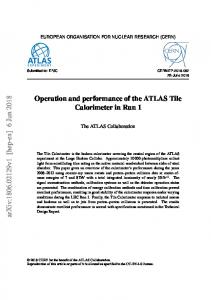
simulated data. The ATLAS EDM prohibits a direct link between the EDM object and the underlying truth particle, but established the relation between the two through an associative container. This association is done independently on each stage of the reconstruction, as explained in Figure 6: on the level of RawDataObject, PrepRawData, Track and finally the Particle objects entering the physics analyses. Several Algorithms and AlgTools exist which establish the association between each container of EDM objects and the truth, depending on what parts of the reconstruction are executed in a given job. Of course they are only executed if the reconstruction chain runs over simulated data.
Identifier
InDetSim Data GenEvent m ap
InDetSim DataCollection m ap
InDet Sim Data
InDetRawData
points to
owns 1...n
PRD_MultiTruthCollection m ultim ap
GenParticle
points to HepMcParticle Link
Trk::Prep RawData
TrkTruthData
1...n
Detailed TrackTruth
1...n
points to Trk::Space Point
DetailedTrackTruthCollection m ultim ap
Truth Trajectory
Track TruthKey
points to
Trk::Track
TrackTruthCollection m ap
InDetSim Event TRT_Uncom pressedHit
Trk::RIO_ OnTrack
owns 1...n
Track Truth
SiHit
points to
points to Particle Particle Truth
ParticleTruthCollection m ap
Rec::Track Particle
Figure 6: Truth objects in the Inner Detector. The link between true and reconstructed particles is made solely via the -TruthCollection container classes and their associative links to both true and reconstructed hits, tracks or particles.
Truth association at hit level As described in [4] there are different sources which can lead to a detector hit, i.e. a signal over the simulated thresholds in each detector. This leads to two possible situations in the truth association: • There is a SimulatedDataObject (SDO) associated to an RDO. Each SDO contains one or more links (HepMcParticleLink) to the truth particle(s) which is/are responsible for the given hit. • An RDO has no corresponding SDO, or the SDO has no valid HepMcParticleLink. This RDO is produced by a low-energy particle (from either signal or pile-up event) or is pure noise. There are differences in treatment of the different sub-detectors: 12
• Pixels: there is one RDO, and possibly one SDO, per cell which contains a signal. • SCT: There is one RDO per group of consecutive strips with a signal (in order to emulate the output of the ROD when working in condensed mode). However there may be an SDO per each of the strips contained in the RDO. • TRT: There is one RDO, and possibly one SDO, per fired straw. The TRT digitization has implemented additional cuts on kinetic energy, below which SDOs are not produced. The package InDetSimData provides the underlying classes [12]. For the following reconstruction stages after the formation of PrepRawData by clustering and calibration, the precise information about the underlying truth is fully retained by the PRD MultiTruthCollection, which is the default for the Inner Detector. Truth association at track level Also for the track level, the Inner Detector reconstruction provides detailed truth information as described in [4] and shown in Figure 6. Here the ambiguity (that a track corresponds to more than one generated particle) arises mainly from close-by tracks and from inelastic interactions or decays, where the true particle type changes along the trajectory. This ambiguity is fully retained by the DetailedTrackTruthCollection which allows linking to more than one true track and uses the TruthTrajectory object to describe particle type changes.
4
Transient and Persistified Objects
This document describes the transient inner detector event data model, that is the data classes which all reconstruction algorithms work with when they create and access event data in memory. The same event data, however, also needs to be stored (“persistified”) on disk and read back. This has several serious implications on the class structure which have led to the decision in ATLAS to separate the transient and persistent data model: • pointers to data and detector geometry objects are replaced by an ATLAS-specific object reference and identification scheme in the persistent model; • object embedding and inheritance are replaced by a flat structure on the persistent side; • the transient data model can evolve while compatibility with old persistent data is maintained; • adapting the bit depth to the significance of measured quantities allows further compression, e.g. use float instead of double for those data members; • the sets and vectors of (persistent) EDM objects can be re-organised to speed up file access. ATLAS uses POOL as an interface to read/write data to root files [5]. Data is being copied between transient and persistent objects before writing and after reading by a set of conversion methods. When this conversion method reads in EDM objects which have pointers, these pointers have to be re-directed to the current memory 13
address of the objects pointed at. This re-direction usually necessitates access to the EDM object’s pointer member, which is by design not allowed to the reconstruction algorithms. The transient-persistent converters therefore have private set-methods inside the EDM classes, see for example Figure 5. An example for the current sizes of the inner detector data objects on disk is given in Table 1 for simulated pp → t¯t (t → blν) events with on average 80 reconstructed tracks per event. The actual data size per event will vary strongly with many different factors, such as the type of event, luminosity as well as further improvements on the persistent data model and number of events per file (i.e. fraction of file structure overhead). Two alternatives for storing Tracks are available: as full tracks with the complete trajectory estimate (a RIO OnTrack, TrackParameters and FitQuality at every detector surface) and as “slimmed” Tracks with the fit results retained only at beginning and end of the track. Using the latter saves a lot of space but drops information which is usually needed by detailed track studies. This information can be fully recovered by fitting the slimmed tracks once more. Object PixelClusters SCT_Clusters TRT_DriftCircles TrackSegments (TRT) Tracks (full) Tracks (slim) TrackParticles PRD_MultiTruth (Pixel) PRD_MultiTruth (SCT) PRD_MultiTruth (TRT) DetailedTrackTruth TrackParticleTruth
Size [kB] in memory 65 150 278 174 954 496 45 10 27 83 7 2
Size [kB] on disk 20 51 75 35 478 102 15 4 10 20 1.3 0.3
Table 1: Persistified inner detector objects and their compressed sizes on disk for simulated t¯t events (MCatNLO, ≥ 1 lepton). Reconstruction was performed and ESD written with release 13.0.30. The per-event size was obtained from averaging over 100 events. The sample contains in total 8044 tracks.
References [1] S. Armstrong (ed), Requirements for an inner detector event data model, ATLAS note ATL-INDET-2002-014 [2] V. Boisvert et al, Final Report of the ATLAS RTF, ATLAS note ATL-SOFT-2003-010 [3] F. Dittus, S. Haywood (eds), ATLAS Inner Detector TDR, CERN/LHCC/97-16 and ISBN 92-9083-102-2.
14
[4] F. Akesson et al, The ATLAS Tracking Event Data Model, ATLAS note ATL-SOFT-PUB-2006-004 T. Cornelissen et al, Updates of the ATLAS Tracking Event Data Model, ATLAS internal ATL-COM-SOFT-2007-008 [5] ATLAS Collab., ATLAS Computing TDR, CERN-LHCC-2005-022 [6] RD Schaffer et al, Definition of Offline Readout Identifiers for the ATLAS Detector, ATL-SOFT-2001-004 [7] http://isscvs.cern.ch/cgi-bin/viewcvs-all.cgi/offline/?cvsroot=atlas : InnerDetector/InDetRawEvent/InDetRawData [8] http://isscvs.cern.ch/cgi-bin/viewcvs-all.cgi/offline/?cvsroot=atlas : InnerDetector/InDetRecEvent/InDetPrepRawData [9] http://isscvs.cern.ch/cgi-bin/viewcvs-all.cgi/offline/?cvsroot=atlas : InnerDetector/InDetRecEvent/SiSpacePoint [10] http://isscvs.cern.ch/cgi-bin/viewcvs-all.cgi/offline/?cvsroot=atlas : InnerDetector/InDetRecEvent/InDetRIO OnTrack [11] http://isscvs.cern.ch/cgi-bin/viewcvs-all.cgi/offline/?cvsroot=atlas : InnerDetector/InDetRecEvent/InDetCompetingRIOsOnTrack [12] http://isscvs.cern.ch/cgi-bin/viewcvs-all.cgi/offline/?cvsroot=atlas : InnerDetector/InDetRawEvent/InDetSimData
15