VOL. 12, NO. 16, AUGUST 2017
ISSN 1819-6608
ARPN Journal of Engineering and Applied Sciences ©2006-2017 Asian Research Publishing Network (ARPN). All rights reserved.
www.arpnjournals.com
AUDIO SIGNALS PROCESSING WITH DIGITAL FILTERS IMPLEMENTATION USING MYDSP Ruthber Rodríguez Serrezuela1, Adrián Fernando Chávarro Chavarro2, Miguel Ángel Tovar Cardozo1, Adriana Gisela Rey Caicedo1 and Carlos Arturo Cabrera1 1
Faculty of Biomedical, Electronic and Mechatronics Engineering, Universidad Antonio Nariño (UAN), Bogota, Colombia 2 Department of Electronic and Telecommunications, Tecnoparque SENA, Bogota, Colombia E-Mail:
[email protected]
ABSTRACT In this document, a software application for Digital Signal Processing is implemented with a MyDAQ device; in the designed application, audio signals from MP3 Files are used as input data. A Labview based software tool GUI is developed for this porpoise to visualize frequency spectrum response. Two specific filters as the Finite Impulse Response (FIR) or (IIR) Infinite Impulse Response were implemented and compared. The procedure and simulation are designed in Matlab to understand the process carried out by the Digital Signal Processor (MyDSP) from National Instruments as a study case in educational activities. Keywords: digital filters, FIR, IIR, Labview, DSP.
INTRODUCTION Advances in technology related to integrated circuits have reached an important impact on technical areas as medicine, aerospace, radar, communications [1] and others [2], [3], [4], applied techniques of digitized signal processing and hardware are widely developed [5]. A deep knowledge of the fundamentals techniques of digital analog signal processing is essential for anyone whose is a needed fordigital application. Applications in digital signal processing have increased since more and are more powerful possibilities offered by modern digital technology [6]. Few years ago, it was unimaginable to have various types of services involving audio signals, but the rise of new technologies is allowing this [7]. Networks integrating voice and data, dialogues between man and machine, transcription of text of a speaker, synthesis from text, identification and verification of speakers, activation or deactivation voice are some examples of the achievements of the digital audio signal processing today [7]. Modern microprocessors are each time faster for being used in more complicated and demanding work [8]. Hence the unavoidable need to develop applications that allow implementing real-world situations to consolidate the acquired knowledge [9]. For a given digital signal processing the procedure begins with the analysis of discrete time system signals, including sampling, discretization and convolution procedures using difference equations, the z-transform, and discrete time Fourier Transform most of the cases An emphasis is made on the differences and similarities in discrete time for Z-transform, and Discrete Fourier Transform [10], important for practical development, research and used as base background knowledge in computer and engineering sciences. This work develops infinite response digital filters with the use of didactic digital signal processor as it is: MyDSP. It can be conclude that with the filter-based
design and a discussion made on the Fourier transform in fast to process digital signals based on the algorithms in Labviewin order to calculate discretely the Fourier transform. PROBLEM FORMULATION Characterization of a filter: impulse response and transfer function In time domain, the impulse response is obtained as an invariant linear system attribute in time, it appear in the output when the input is an impulse signal. A digital filter consists of the discrete between the input and its impulse response system representation is performed. This relationship can be described by the following equation: ∞
[ ] = [ ] ∗ ℎ[ ] = ∑
=−∞
ℎ[ ] [ − 𝐾]
(1)
One of the main advantages of a linear invariant filter describe that it can be determined by the time domain impulse response and transfer function over the Z domain. Only SLTI filters check the superposition property: based on this we can say SLTI that filtering an addition of audio signals is equal to add each separately filtered signal. Moreover, the properties of causality and stability permit the filter to be done. Thus, with the estimated values of Z in its domain, the transfer function H(z) relates the system input to the output of LTI, which is given for this case. Thus the impulse response is equal to the result of a transfer function in the Z transform: 𝑇. .
[ ] = [ ] ∗ ℎ[ ] → =
= ∑∞ 𝑛= ℎ[ ]
=
(2)
−𝑛
(3)
Finally if we refer to the frequency domain, which is part of Z domain, which represents the frequency
4848
VOL. 12, NO. 16, AUGUST 2017
ISSN 1819-6608
ARPN Journal of Engineering and Applied Sciences ©2006-2017 Asian Research Publishing Network (ARPN). All rights reserved.
www.arpnjournals.com response will correspond to the discrete Fourier transform sequences (TFSD) of the impulse response: − 𝜋 𝑛 = ∑∞ (4) 𝑛= ℎ[ ]
Within filters, the transfer functions as well as the impulse response have determined the following:
𝐴
The gain (G (f)) is determined as the amplification of the signal which is located it the input related to the output. If the amplification is negative, we talk about attenuation: =
|𝐻
𝐻𝑟
|
|
(6)
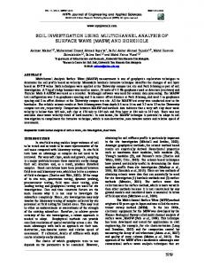
The amplitude response of an ideal filter is 1 on the passband and 0 respectively to the attenuation of the band Figure-1.
𝜃
In filter, The phase in the transfer function response is defined as the phase of the impulse response =∠
The frequency response areas are determined in |and phase𝜃ℎ . detail by the module| | 𝜃ℎ . In this case, if we have =| the input signal frequency and the previous filter, so the same module characterized and the output phase signal they are as follows:
(5)
A filter in question amplitude response is specified as the modulus of the frequency response of the filter: =|
ranges outside the attenuation step determine the maximum limit of the passband and are called stopband. If we find ideal filters, attenuation and frequency step equally match the cutoff frequency.
(7)
𝜃
=
= 𝜃ℎ
∗
(8) +𝜃
(9)
|refers to the filter gain, phase The module| 𝜃 determines how much a filter is delayed. A very important property of the filter related to the phase is group delay: 𝜏 =−
𝑑𝜃
(10)
𝜋𝑑
The output signal is evaluated with each group delay, which is initially the input by samples for each frequency. Thus, it is important to evaluate the overall delay that logically a signal experiences logically. If it is constant the group delay it means that the phase will be linear (so that the frequencies will delay). In case the group delay is different depending on the frequency, a distortion occurs in the respective signal spectrum. Specifying the input-output of a filter: finite difference equations A practical way of exposing the correlation between the input and output of the casual filter is with the equation in finite differences in order to use it. The equation is described by the detailed formula for the sample n output samples that only depends on present and past input. A general finite difference equation is as follows:
Figure-1. Ideal response for low pass filter, Source: Author. The number of coefficients in the transfer function indicates the order; in addition input signals in relation to the previous output are used to compute y [n]. However, the order of a filter is obtained by defining as the order of the impulse response. And, the order of a given polynomial is referred as the highest value of the exponent of the same polynomial. The opportunity to be a rational function is defined as the maximum in the relation of numerator and denominator polynomial orders.
In the passband filter, the frequency range that passes from input to output without being attenuated; so the attenuated band is complementary. The frequencies
y[n] = b x[n] + b x[n − ] + ⋯ + b x[n − M] − a y[n − ] − ⋯ − a y[n − N]
(11)
That represented in summations is: [ ]=∑ =
[ − 𝑖] − ∑ =
[ − 𝑖]
Where [ ]is the discrete signal belong to entry, [ ] is the output signal, andconstants 𝑖 = , , , … and 𝑖 = , , , , … are the number or fixed number of coefficients filter. The transfer function is obtained by analyzing the equations in the domain Z:
4849
VOL. 12, NO. 16, AUGUST 2017
ISSN 1819-6608
ARPN Journal of Engineering and Applied Sciences ©2006-2017 Asian Research Publishing Network (ARPN). All rights reserved.
www.arpnjournals.com 𝑇. .
[ ] = [ ] ∗ ℎ[ ] →
=
=
(13) (14)
We know that: T.Z.
y[n] = ∑ bi x[n − i] − ∑ a y[n − i] ⇒ y z = ∑ bnX z z −n − ∑ an Y z z −n
So,
i=
i=
.[ + ∑
Thus,
=
𝑛=
∑𝑁 𝑛=
𝑛
[ +∑𝑁 𝑛=
𝑛
𝑛
−𝑛
] =∑
−𝑛
𝑛=
n=
𝑛
that reason, they are called FIR filters (finite impulse response, or finite impulse response).
n=
−𝑛
RESULTS With results values achieved by simulating in Matlab, two digital filters were implementedin a Labview software application. The Figure-3 shows the front panel composed by two meter type digital controls. These indicators clearly show the R.M.S value of 𝑖 and 𝑖 . Input signals from themy DAQ. and labelsappearwith [Vrms], both use logarithmic scale 0.001 to 1, with DBL numeric data type, respectively.
(15)
−𝑛 ]
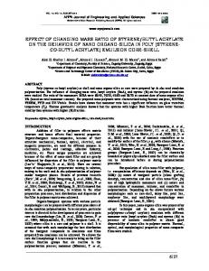
The transfer function can be written in terms of roots in the polynomials as follows: H z =
∑n= bn z −n Y z b ∏n= = = −n X z [ + ∑n= a n z ] a ∏Pk=
− zk z − − pk z −
Where zeros in the numerator,and the poles in the denominator corresponds to the transfer function is infinite equal.
Figure-3. Labview user interface application for digital filter implementation., Source: autor.
Figure-2. Example diagram of poles and zeros, Source: Author. There are two different types of filters that can distinguish a filter finite difference equation: Recurring Filters: these filters have an infinite number of different samples of the impulse response zero for those reasons are rated as IIR (or infinite impulse response or infinite impulse response).
Similarly, there are two displays in a graphical control type Waveform Chart which show the input signals in real time directly from myDAQ. Its label: Signals in the time domain. There is another type Wave graphical control chart figure, which is tagged: Complete set. This shows the signals from the block that converts the signals in the frequency domain using the fast Fourier transform complex FFT. Through two graphical types, add a Magnitude of the frequency spectrum, which show signals from (R.M.S) block fast Fourier transform as a result. In the final part is a graphic wave graph type control, which is labeled: IIR Lowpass filter Butter work, which shows the output filtered signals.
Recurring Filters: these are filters in which the coefficients are zero and therefore depend on the indicated input signal. It has a finite number of samples other than zero impulse response filter for
4850
VOL. 12, NO. 16, AUGUST 2017
ISSN 1819-6608
ARPN Journal of Engineering and Applied Sciences ©2006-2017 Asian Research Publishing Network (ARPN). All rights reserved.
www.arpnjournals.com
Figure-4. Control panel for the Labview user interface in audio processing.Source: Author. It was set up by the DAQ Assistant leaving and as inputs ports with a signal range +10 volts to -10 volts. The acquisition mode is continuous, with a number of samples 10,000 and at a rate of 50 KHz. Filter design was used to calculate que IIR and FIR filters, frequency response in amplitude and magnitude, Phase and impulse response can be represented by graphical analysis represented in Figure-5.
Figure-5. Low pass filter design using Matlab. Source: Author. Spectral Measurements are set up by selecting the extent (R.M.S.) in decibels (dB) with Hamming window type. The windows simply deduce that mathematical functions are frequently used in the analysis, development and signal processing in order to avoid discontinuities at the end and beginning of the diagram blocks. Deduced transfer function can be observed in Figure 6 where poles and ceros are located in complex plane, using matlab functions.
Figure-6. Poles and ceros used to represent IIR and FIR filters. Source: Author.
CONCLUSIONS Audiosignals for being invariant, nonlinear and in homogeneous signals have the peculiarity that are difficult to characterize, nowadays due to the advancement of new electronic devices such as MyDSP and development environments Labview can make any kind of treatment signals using simple algorithms. The workcan be easily implemented (using a wizard) broadly mathematical algorithms forscanning, processing and processing of audio signals into digital signals and to parameterize the audio signal in real time. Matlab is very important in the design of any type of filter system, with it can bedesigned and simulated any type of digital filter with simple implementation spareus the same tool. Here the fast Fourier transform is developed because its computational cost is lower. For the implementation of the FIR filter coefficients results in the simulation in Matlab were taken, the MyDSP can handle from 2 to 600 FIR coefficients and to the tenth order. Labview GUI is flexible for programming digital filters and performing for example the Fast Fourier Transform, this can be written in graphical languaje. Matlab is an excellent tool to simulate algorithms and test models obtaining the necessary coefficients for the implementation of the FIR and IIR filters. FIR filters can conclude that this type of filter increase the number of coefficients and significant ly improves the filter response band. When noised signal are analyzed, filtering processattenuates the signal and other components of noise are removed. REFERENCES [1] Kehtarnavaz N. and Kim N. 2011. Digital signal processing system-level design using LabVIEW. Newnes.
4851
VOL. 12, NO. 16, AUGUST 2017
ISSN 1819-6608
ARPN Journal of Engineering and Applied Sciences ©2006-2017 Asian Research Publishing Network (ARPN). All rights reserved.
www.arpnjournals.com [2] Kumar A. 2015. Complementary metal-oxide semiconductor implementation of digital filters for signal processing applications, IET Circuits, Devices and Systems. [3] Gurumurthy S., Senthilkumar, N.C, Ghalob, M.R. 2014. A study of digital signal processing application for remote patient monitoring system using live EEG data transmission, International Journal of Applied Engineering Research. [4] Molina M.G, Cabrera M.A, Ezquer R.G, Fernandez P.M, Zuccheretti E. 2013. Digital signal processing and numerical analysis for radar in geophysical applicaions, Advances in Space Research. [5] Chi N., Wang Y. Wang Y., Li R. Shang H. 2013. Application of digital signal processing in high speed visible light communication systems. Proceeding of SPIE-The International Society for Optical Engineering. [6] Safarian C. Oguntunmi T. Kozacky W.J. Mohanty B.K. 2015. FPGA implementation of LMS-based FIR adaptive filter for real time digital signal processing applications. International conference on Digital Signal Processing. [7] Alan V. Oppenheim, Alan S. Willsky, Signal and Systems 2nd edition, Prentice Hall. [8] Kalantzopoulos A., Karageorgopoulos D. and Zigouris E. 2008. A LabVIEW based remote DSP laboratory. International Journal of Online Engineering (iJOE). 4, p. 36. [9] Yoder M. and Black B. 2006, September. Teaching DSP first with LabVIEW. In Digital Signal Processing Workshop, 12th-Signal Processing Education Workshop, 4th (pp. 278-280). IEEE. [10] Kehtarnavaz N. and Gope C. 2006 May. DSP system design using LabVIEW and Simulink: a comparative evaluation. In Acoustics, Speech and Signal Processing, 2006. ICASSP 2006 Proceedings. 2006 IEEE International Conference on (2: II-II). IEEE. [11] Arellano Mejía M. M., Cabascango R. and Orlando T. 2002. Diseño y construcción de un sistema de programación de DPSs basado en labview (Doctoral dissertation, Quito: EPN, 2002.).
[12] Tabares A. F. G. and Ruiz J. N. V. 2012. Aplicación de procesamiento de señales telefónicas usando Labview. Scientia et Technica. 2(50): 203-210. [13] Bilski P. and Winiecki W. 2002. Virtual spectrum analyzer based on data acquisition card. Instrumentation and Measurement, IEEE Transactions on. 51(1): 82-87. [14] Hercog D., Gergič B., Uran S. and Jezernik K. 2007. A DSP-based remote control laboratory. Industrial Electronics, IEEE Transactions on. 54(6): 3057-3068. [15] Gallardo S., Barrero F. J. and Toral S. L. 2005. Virtual instrumentation laboratory based on LabVIEW. A case study: A DSPs course. Enseñanza. 1, 2. [16] Jamal R. 1994. Graphical object-oriented programming with LabVIEW. Nuclear Instruments and Methods in Physics Research Section A: Accelerators, Spectrometers, Detectors and Associated Equipment. 352(1): 438-441. [17] Gani A. and Salami M. J. E. 2002. A LabVIEW based data acquisition system for vibration monitoring and analysis. In Research and Development, 2002. SCOReD 2002. Student Conference on (pp. 62-65). IEEE. [18] Bansal D., Khan M. and Salhan A. K. 2009. A computer based wireless system for online acquisition, monitoring and digital processing of ECG waveforms. Computers in biology and medicine. 39(4): 361-367. [19] Serrezuela R. R. and Chavarro A. F. C. 2016. Multivariable Control Alternatives for the Prototype Tower Distillation and Evaporation Plant. International Journal of Applied Engineering Research. 11(8): 6039-6043. [20] Azhmyakov V., Rodriguez Serrezuela R., Rios Gallardo A. M. and Gerardo Vargas W. 2014. Approximations Based Approach to Optimal Control of Switched Dynamic Systems. Mathematical Problems in Engineering. [21] Serrezuela, R. R., Chavarro, A. F. C., Cardozo, M. A. T., & Zarta, J. B. R. (2016). An Optimal Control Based Approach to Dynamics Autonomous Vehicle. International Journal of Applied Engineering Research, 11(16), 8841-8847.
4852
VOL. 12, NO. 16, AUGUST 2017
ISSN 1819-6608
ARPN Journal of Engineering and Applied Sciences ©2006-2017 Asian Research Publishing Network (ARPN). All rights reserved.
www.arpnjournals.com [22] Azhmyakov, V., Serrezuela, R. R., & Trujillo, L. G. (2014, October). Approximations based optimal control design for a class of switched dynamic systems. In Industrial Electronics Society, IECON 2014-40th Annual Conference of the IEEE (pp. 9095). IEEE. [23] Carvajal R. J. H., Serrezuela R. R., Quimbayo López J. A. and Roa Perdomo K. L. (2016), LQR Hybrid Approach Control of a Robotic Arm Two Degrees of Freedom, International Journal of Applied Engineering Research, 11(17), 9221-9228. [24] Serrezuela, R. R., Villar, O. F., Zarta, J. R., & Cuenca, Y. H. (2016). The K-Exponential Matrix to solve systems of differential equations deformed. Global Journal of Pure and Applied Mathematics, 12(3), 1921-1945. [25] Rodríguez Serrezuela, R., & Carvajal Pinilla, L. A. (2015). Ecological determinants of forest to the abundance of Lutzomyia longiflocosa in Tello, Colombia. International Journal of Ecology, 2015.
4853