VOL. 10, NO. 22, DECEMBER, 2015
ARPN Journal of Engineering and Applied Sciences
ISSN 1819-6608
©2006-2015 Asian Research Publishing Network (ARPN). All rights reserved.
www.arpnjournals.com
DESIGN, APPLICATION AND COMPARISON OF PASSIVE FILTERS FOR THREE-PHASE GRID-CONNECTED RENEWABLE ENERGY SYSTEMS 1
Mojgan Hojabri1 and Mehrdad Hojabri2
Faculty of Electrical and Electronics Engineering, University Malaysia Pahang, Pekan, Malaysia Electrical Department, Science and Research Branch, Islamic Azad University, Kermanshah, Iran E-Mail:
[email protected]
2
ABSTRACT Second and third-order passive filters (LC and LCL) are interesting filters to use for grid-connected PWM inverters. Because of the stability problems of these filters around resonance frequency, series and damping resistor can be add to an LCL filter. However, the resistor value has impact on the filter respond, voltage and current harmonic distortion and filter power loss. In this paper, the mathematic characteristics of LC, LCL filter, series and parallel damping LCL filters will be described with their design to apply in 3-phase PV grid-connected inverter. And, simulations have down to validate the theoretical analysis of the filters on filter performance, power quality and filter power loss for 3-phase grid-connected renewable energy system application. Keywords: passive filters, LCL filters, filter power loss, harmonic distortion, renewable energy systems.
INTRODUCTION Filters are main parts of a renewable energy system. First- order passive filters are L type, which are generally use for controlling grid-connected inverter. The main disadvantage of this type of filters is their big size. Another type of the passive filters is LC filters (secondorder). Because of the big size of the inductor, the size of this filter is large. Moreover, time delay and resonance frequency are another drawbacks of LC filters. Compared with a first-order and second-order filters, a third-order LCL filter has lower coast and smaller size in applications above several kilowatts. However, resonance frequency is still as a problem of these filters. To repress the resonances of an LCL filter, active damping [1]–[2] or passive damping [3]–[5] can be used. The price of active filter is high due to the additional cost of the sensors and control system. Because of the low cost and simple circuit in a stiff grid application, a passive damping strategy is more preferred. A simple damped LCL filter is an LCL filter with series or parallel resistor with capacitor. By adding a resistor to the filter circuit, the power loss will increase. So, finding the optimum resistor value to decrease the peak resonance of LCL filter is very important. Therefore, in this paper characteristics of LC, LCL filter, series and parallel damping LCL filters will be discussed. Since maintaining a good power quality is important for the reliable operation of the system and loads [6], these filters will be applied to a three-phase PV system. Then, the inverter output will be filtered in order to obtain low voltage and current distortion. And also, the filter impacts on grid current will discussed. Principle of passive filters First, grid-connected converters are the interface to connect renewable energy sources to the power system. To reduce the harmonics injected by the converters a high value of input inductance should be used. However, L filter design is easy but in application
above several kilowatts it becomes expensive because of using large filter reactor. Moreover, the system dynamic response becomes poor. LC filter The filter consists of an inductance in series with the inverter and a capacitance in parallel with the grid (Figure-1). By using this parallel capacitance, the inductance can be reduced, thus reducing costs and losses compare with L filter. By using a large capacitance, other problems such as high inrush currents and high capacitance current at the fundamental frequency or dependence of the filter on the grid impedance for overall harmonic attenuation will appear [7].
Figure-1. Grid-connected LC filter. The LC filter transfer function of grid side voltage and inverter input voltage in grid-connected mode of operation is given by Equation. (1). The bode plot is presented in Figure-2.
G(s)
Ug U inv
1 2
S LC 1
(1)
10691
VOL. 10, NO. 22, DECEMBER, 2015
ARPN Journal of Engineering and Applied Sciences
ISSN 1819-6608
©2006-2015 Asian Research Publishing Network (ARPN). All rights reserved.
www.arpnjournals.com
Figure-2. Bode plot for LC filter.
Figure-4. Bode plot of LCL filter.
LCL filter An alternative and attractive solution of first and second order filter problems is to use an LCL filter as shown in Figure-3. With this solution, optimum results can be obtained in the range of power levels up to hundreds of kilovolt amperes, still using quite small values of inductors and capacitors [15].
LCL filter with series damping resistor From the transfer function of LCL filter it is clear that, at the frequency of it has high gain (infinite ‘Q’). The simplest solution may be the addition of series resistance with the capacitor to reduce the ‘Q’ as the capacitor current is most responsible for resonance in LCL filter. Figure-5 shows the series damping topology.
Figure-3. Grid-connected LCL filter. Compared with a first-order L filter, an LCL filter can better decoupling between filter and power grid. Moreover, excellent attenuation of bode -60 dB/decade to the switching frequency will obtain. But, grid impedance reflected back to the converter side is generally very less. So, if the resonance is excited, the oscillation of that can continue forever and it can make the entire system very vulnerable. This resonance effect can cause instability voltage or current around the resonant frequency. In order to solve this problem, damping resistor can be add to the LCL circuit. The purpose of applying this damper is to reduce the attenuation and damping (Qfactor) at the characteristic resonance frequency, as it is indicated in Figurer-4. The LCL filter transfer function of line side current and inverter input voltage in gridconnected mode of operation is given by Equation. (2).
G ( s)
I2 1 U inv S 3 L1 L2C ( L1 L2 ) S
Figure-5. Grid-connected series damped LCL filter.
It is also clear from the frequency response of capacitor current. It carries basically resonant component and very less fundamental as well as switching component. Transfer function for this filter is shown as (3). G(s)
I2 1 SRC 3 Uinv (L1L2C)S RC(L1 L2 )S 2 (L1 L2 )S
(3)
As it is shown in Figure-6 by increasing the series resistor value in Equation. (3), damping effects to suppress of the peak resonance become well. However, in high frequency the filter respond is better as indicated it Figure-6.
(2)
10692
VOL. 10, NO. 22, DECEMBER, 2015
ARPN Journal of Engineering and Applied Sciences
ISSN 1819-6608
©2006-2015 Asian Research Publishing Network (ARPN). All rights reserved.
www.arpnjournals.com
G(s)
I2 R Uinv (L1L2RC)S3 (L1L2 )S 2 R(L1 L2 )S
(4)
Figure-9 presents the bod plot of the parallel damped LCL filter for different resistors. As it indicated in this figure, in low and high frequency filter has a same action. But, the peak resonance will be increased by increasing the resistors value. So, the filter action is different around resonance frequency with different resistors.
Figure-6. Damping by changing series resistor. The bode plot is given for the line side current Vs inverter output voltage in Figure-7. As it clear from (3) by increasing the value of resister, the damping effect in Figure-5 become well as it is indicated in Figure-6. And, it cause the lower Q factor.
Figure-9. Damping by changing parallel resistor.
Figure-7. Bode plot of LCL filter with series damping resistor. LCL filter with parallel damping resistor Another way to suppress the resonance in LCL filter is using a parallel resistor with the capacitor as it shown in Figurer-8.
Figure-8. Grid-connected parallel damped LCL filter. The transfer function of parallel damped LCL filter is given by(4). And, the bode plot is presented in Figure-10 for this filter.
Figure-10. Frequency response of LCL filter with parallel damping resistor. Filter design A typical low pass LC filter is shown in Figure-1. The LC low pass filter is a second order filter which eliminates all high order harmonics from the PWM output of the inverter so that the input voltage of the grid become a pure sinusoidal wave of 60 Hz. The cut-off frequency (fc) of the low pass filter is selected to get the current THD less than 5% [8]. The attenuation effect of LC filters can be increased by decreasing the filter cut-off frequency against the switching frequency of inverters according to ) as it indicated in Figure-2. However, 40log ( f sw f
cutt
off
the filter cut-off frequency limits the control band-width of
10693
VOL. 10, NO. 22, DECEMBER, 2015
ARPN Journal of Engineering and Applied Sciences
ISSN 1819-6608
©2006-2015 Asian Research Publishing Network (ARPN). All rights reserved.
www.arpnjournals.com inverter systems. Increasing the control bandwidth is important for fast operation of the inverter system and also for precise voltage compensation without a phase delay at higher-order harmonics. Thus, there is a trade-off between the attenuation effect and the control bandwidth in the design of LC filters. Generally, the value of fc is kept below 1/10th of the inverter switching frequency [9]. The selection of the filter inductance, L, should be such that the voltage drop across the inductor is less than 3% of the inverter output voltage [10]. Then, the value of L can be calculated by (5) - (7).
fc
1 f sw 10
I L max (2fL) 0.03U inv
1 (2f c ) 2 L
Qc
Vl (0.05 ~ 0.1)U g
(8)
2. Where Vl is the inductor voltage loss and U g is the line voltage. Typically, the ripple current can be chosen as 0.15 ~ 0.25 of rated current. In this paper, the ripple current is selected as 20% of the rated current. The maximum current ripple can be derived as in (9) [12]: U dc 0 . 2 I rated 8 Lf sw
resonant
10 f1 f res 0.5 f sw
Prated g cos
1 2
(12)
L1 2 0 . 5 f sw L1 L 2 C
(13)
2 3Vrated 3V 2 2 rated 3(2f1 )CVrated 5% Prated Xc (1 ) c
(14)
Where Vrated is the phase voltage (RMS), Prated is the rated power [15]. Qc is the absorbed reactive power by capacitor. Moreover, inverter-side inductor can be considering as 4 to 6 times bigger than the grid-side inductor [11]: (15)
The purpose of the damping is to reduce the Qfactor at the characteristic resonance frequency. It is easy to achieve by inserting a resistor in series or parallel with the capacitor. Its characteristic resonance frequency, res , can be defined by (16) and (17) [12]: res
R
L1 L2 L1 L2 C f
(16)
1 3 res C
(17)
Table-1. Filter parameters.
(9)
frequency should be where f1 is the grid voltage
frequency and f sw is the switching frequency. 4. Let the high order harmonic flow through the capacitance, and the low order harmonic flow through the inductance. 5. Moreover, generally the reactive power absorbed by the filter-capacitor should be less than the rated active power of the system. Then,
Qc Prated
3U
L1= (4~6)L2
1. The voltage drop of the filter inductor is smaller than 5% 10% of the network voltage under the rated circumstances [11].
3. The
I rated
(6)
(7)
(11)
Where,
10 f 1
To design an LCL passive filter several rules should be considered as listed in below.
I L 1 max
(2f1 ) LPrated 0.1U g 3U g cos
(5)
Where I L max is the maximum RMS value of the load current and f is the frequency of the output voltage, U inv . The filter capacitance can be calculated from the resonance frequency as below: C
Where is the reactive power factor and it must be less than 5%. Therefore, by considering the above constraints in this paper:
(10)
SIMULATION RESULTS The SIMULINK in MATLAB software is used to simulate the system which is shown in Figurer-11. In this paper, the simulation for all filter types in a 20 kW PV grid-connected application is designed. In this simulation a 72 volts battery is considered as the output of a PV array. And, a tuned PI controller is implemented to control the grid side voltage. When the load is equal to 41W, the RMS
10694
VOL. 10, NO. 22, DECEMBER, 2015
ARPN Journal of Engineering and Applied Sciences
ISSN 1819-6608
©2006-2015 Asian Research Publishing Network (ARPN). All rights reserved.
www.arpnjournals.com value of phase-phase voltage is 220V, switching frequency is 2kHz and the fundamental frequency is 50Hz.
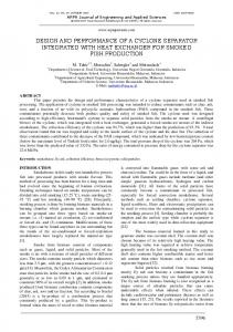
As it clear in Figurer-12, resonant peak is reduced with a series resistor. And also, it is completely suppressed by parallel damping resistor with the same value of resistor. Moreover, in high frequency the damping effect to eliminate the harmonic distortion of parallel resistor is better than series which is clear from the slope of the bod plot in Figurer-12. It can be proving in decreasing the amount of total harmonic distortion of current at gridconnected which is presented in Figurer-13.
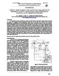
Figure-11. Grid-connected PV system. Choosing the cut-off frequency of 100Hz for a 2kHz switching frequency from (5), the inverter’s expected maximum load current of 200A, the values of L and C determined for the model were 60mH and 42.22µF respectively using (5) - (7) formulas. Referring to the design procedure in the previous part, the parameters of LCL filters are calculated. Total inductor will be calculated between 1.88mH and 4.78mH using (9) – (11) formulas. So, in this paper total inductor is considered as 4.5mH. By considering L1 = 4 L2 from (15), L1 and L2 are defined as 3.6mH and 0.9mH. Capacitor value also is limited between 35 µF and 98 µF from (13) and (14). Therefore, C could be considered as 40µF. In this paper, damping resistor is calculated by (17), and it is equal to 1.41Ω. Filter Types Active power loss(kW) Reactive power loss(var) LC 0.587 -306 LCL 10.75 35 LCL with series R 10.75 35 LCL with parallel R 11.9 7180 Inductor value for LC filter which is calculated before is around 67 times bigger than the inductor of LCL filter. However, increasing the inductor size has many disadvantages like high cost and weight of the filter. Moreover, voltage drop on the inductor will be increased which cause the system power loss. Figurer-12 shows the bode plot of LCL, series damping and parallel damping LCL filters to compare. As it shown in this figure, in high frequency, LCL filter decreases with 60dB/decade which can eliminate highorder harmonic effectively compare with damping filter. However, there is a resonant peak with high amplitude which will distort the grid current seriously. With passive damping method, the resonant peak can be suppressed with a resistor. But in high power system, it will cause unacceptable losses. Modern control theory indicates that the stability of a system greatly depends on its state and control the state variants properly can stabilize the system.
Figure-12. Bode plot comparison of LCL, series and parallel damped LCL filters. For this case study, the same damping resistor is used in both series and parallel damping LCL filter. Current THD for all filters’ application is shown in Figurer-13. As it clear, total harmonic distortion for the LC filter is less than the LCL filter. But, the voltage THD will increase by 0.02%. By adding a damper resistor, the current THD become reduce. The current THD will be equal to 0.27% and 0.16 respectively. By calculate the input and output power of the filters, the filter power loss can be obtain. The active and reactive power loss for all filters is presented in Table-2. Based on these data, LCL filter with series damping has 99.5 percent less reactive power compare to the LCL filter with parallel damping resistor.
Table-2. Filter power loss.
10695
VOL. 10, NO. 22, DECEMBER, 2015
ARPN Journal of Engineering and Applied Sciences
ISSN 1819-6608
©2006-2015 Asian Research Publishing Network (ARPN). All rights reserved.
www.arpnjournals.com harmonic injection to the grid and filter power loss, LCL filter with series damping resistor is the best choice for grid-connected renewable energy systems.
REFERENCES [1] Y. Tang, P. PLoh, P. Wang, F. Choo and F. Gao. 2012. Exploring inherent damping characteristic of LCL-filters for three-phase grid-connected voltage source inverters. IEEE Transactions on Power Electronics. Vol. 27, No. 3, pp. 1433– 1443. [2] R. Dannehl, M. Liserre and F. Fuchs. 2011. Filterbased active damping of voltage source converters with LCL filter. IEEE Transactions on Industrial Electronics. Vol. 8, No. 8, pp. 3623–3633. [3] R., Turner, S. Walton and R. Duke 2010. Stability and bandwidth implications of digitally controlled grid-connected parallel inverters. IEEE Trans. Power Electron. Vol. 57, No. 11, pp. 3685–3694. [4] A.A. Rockhill, V. Liserre, R. Teodorescu R. and R. Rodriguez R. 2011. Grid-filter design for a multimegawatt medium-voltage voltage-source inverter. IEEE Transactions on Industrial Electronics. Vol. 58, No. 4, pp. 1205–1217. [5] P. hannegowda and V. John. 2010. Filter optimization for grid interactive voltage source inverters. IEEE Transactions on Industrial Electronics. Vol. 57, No. 12, pp. 4106–4114. [6] M. Hojabri and A. Toudeshki. 2013. Power quality consideration for off-grid renewable energy systems. Energy and Power Engineering. doi:10.4236/epe, Vol. 5, No. 5, pp. 377-383.
Figure-13. Current harmonic distortion of (a) LC filter, (b) LCL filter, (c) LCL with series damping filter and (d) LCL with parallel damping filter. CONCLUSIONS A 20 kW three-phase grid-connected inverter with a PI tuned controller is implemented to validate the designed LC, LCL and damped LCL filters and compared their performance. Besides the resonance frequency problem, LCL filters are preferred than LC filters because of their size, weight and price. To overcome on the instability problems of LCL filters, damping LCL filters are recommended. However, LCL filter with series damping resistor can eliminate more harmonic distortions compare to the parallel one. But, the filter power loss for LCL filter with parallel damping resistor is higher than series damping. Then, in conclusion it can be seen by considering the filter size, weight, price, stability,
[7] Antunes F. L. M. and Araujo S. V. 2007. LCL filter design for grid-connected npc inverters in offshore wind turbines. The 7th International Conference in Power Electronics. Daegu, Korea. pp. 1133–1138. [8] H. Kojabadi. 2006. A Novel DSP-based currentcontrolled PWM strategy for single phase grid connected inverters. IEEE Transactions on Power Electronics. Vol. 21, No. 4, pp. 985-993. [9] H. Kim and S.K, Sul. 2011. A novel filter design for output LC filters of PWM inverters. Journal of Power Electronics. Vol. 11, No. 1, pp. 74-81. [10] K.H. Ahmed. 2007. Passive filter design for three phase inverter interfacing in distributed generation. Electric Power Quality and Utilization. Vol. 8, No. 2, pp. 49-58. [11] X. Renzhong, X. Lie, Z. Junjun and D. Jie. 2013. Design and research on the LCL filter in three-phase
10696
VOL. 10, NO. 22, DECEMBER, 2015
ARPN Journal of Engineering and Applied Sciences
ISSN 1819-6608
©2006-2015 Asian Research Publishing Network (ARPN). All rights reserved.
www.arpnjournals.com PV grid-connected inverters. International Journal of Computer and Electrical Engineering. Vol. 5, No. 3. [12] Ye Z., Sinha G., Yuan X. and Wang T. C. 2003. Output filter design for a grid-interconnected threephase inverter, IEEE Annual Conference. [13] Hojabri M., Hojabri M., Toudeshki A. 2015. Passive damping Filter design and application for three-phase PV grid-connected inverter. International Conference on Technological Advances in Electrical, Electronics and Computer Engineering (ICTAEECE). pp. 17-23.
10697