M u s c u l o s k e l e t a l I m a g i n g • Te c h n i c a l I n n ov a t i o n Weiss et al. Augmented Reality MRI-Guided Needle Placement Musculoskeletal Imaging Technical Innovation
Augmented Reality Visualization Using Image-Overlay for MR-Guided Interventions: System Description, Feasibility, and Initial Evaluation in a Spine Phantom Clifford R. Weiss1 David R. Marker 1 Gregory S. Fischer 2 Gabor Fichtinger 3 Antonio J. Machado1 John A. Carrino1
OBJECTIVE. The purpose of this article is to provide a preliminary user assessment of ImageOverlay, an augmented reality system for MRI-guided needle placement, in a spine phantom. CONCLUSION. Image-Overlay can be used to successfully target lumbar facet joints with high accuracy and minimal insertions. This is potentially useful for other interventional MRI applications. Additional clinical assessment is needed.
Weiss CR, Marker DR, Fischer GS, Fichtinger G, Machado AJ, Carrino JA
RI increasingly is being used for interventional procedures because of its unparalleled soft-tissue contrast, multiplanar capabilities, and lack of ionizing radiation [1]. Technologic hurdles to widespread adoption of interventional MRI include the balance between patient access and image quality. Patient access is best in open systems. However, these open systems offer lower field strength, less homogeneity, poorer image quality, and no advanced MRI techniques (such as temperature mapping and metabolic imaging). Conversely, although closed-bore high-field superconducting systems provide the best image quality, these scanners may limit patient access. Augmented reality (AR) systems have the potential to remove the barrier between patient access and high-quality imaging by allowing previously acquired imaging data from the magnet to be projected onto a patient outside the bore. Widespread adoption of AR systems lags because they traditionally require prohibitively expensive and complex equipment. We describe a relatively simple, low-cost AR system (ImageOverlay) for interventional MRI procedures in a spine phantom and conducted preliminary user assessment.
Keywords: augmented reality imaging, interventional radiology, MR-guided interventional procedures, musculoskeletal radiology, spine phantom DOI:10.2214/AJR.10.5038 Received May 22, 2010; accepted after revision August 25, 2010. 1
Musculoskeletal Division, Russell H. Morgan Department of Radiology and Radiological Science, Johns Hopkins University School of Medicine, 601 N Caroline St., JHOC 5165, Baltimore, MD 21287. Address correspondence to J. A. Carrino (
[email protected]).
2 Department of Mechanical Engineering, Worcester Polytechnic Institute, Worcester, MA. 3 School of Computing, Queen’s University, Kingston, ON, Canada.
WEB This is a Web exclusive article. AJR 2011; 196:W305–W307 0361–803X/11/1963–W305 © American Roentgen Ray Society
M
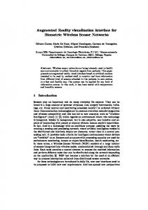
Materials and Methods Image-Overlay System Design Image-Overlay requires a flat-panel display to be aligned with a semitransparent mirror that is mounted just outside the bore of an imaging scanner (Fig. 1). The specifications for the hardware have been previously detailed in studies by Fich-
tinger et al. [2] and Fischer et al. [3]. Axial MR images are displayed on the liquid crystal display (LCD) and visible on the semitransparent mirror projected on the patient outside of the scanner bore. The system hardware components are relatively low in cost: laptop computer ($1,200), MRI-compatible LCD screen (we used a $300 standard LCD outside of the 5 Gauss line but setup changed to $10,000 custom-built, MRI-compatible screen), frame materials and machining costs ($1,000), mirror ($300), and interconnection box with associated wiring, power cords, and laser lights ($500).
System Calibration Calibration is accomplished in three stages [4]. Stage 1: Overlay laser plane and the image display alignment—This is a one-time calibration accomplished during construction. The laser is adjusted such that it passes through the intersection of the LCD and mirror planes while maintaining a fixed angle of 60° with respect to the mirror. Stage 2: Overlay laser plane and MR image plane alignment (hardware calibration) —This stage is performed at the scanner using a marked phantom placed on the scanner table to match the alignment of the overlay with the transverse laser plane of the MR scanner landmarking system. Stage 3: Overlay image and MR image scaling and alignment (software calibration) —Image scaling (Fig. 2) is performed to match the overlay image with the MR image. Variable linear scaling needs to be accomplished between the MR image and the overlay display image to correct the size in the mirror. The pixel size of the display is constant and is either known from the manufacturer’s specifications or measured. The pixel size of the
AJR:196, March 2011 W305
Weiss et al. Mount
Display
Half mirror
Fig. 1—Schematic of Image-Overlay shows concept of 2D image-overlay system. Semitransparent mirror and screen is mounted over patient outside scanner. Angle between screen and mirror is matched to angle between mirror and image plane, in present study at 60°.
Image
Gantry
Table
MR image is extracted from the DICOM header or calculated as the ratio between the field of view (in millimeters) and the image size (in pixels). Subsequently, in-plane rotation and translation are adjusted until each fiducial marker on the phantom coincides with its counterpart in the image.
Validation System A standardized reproducible electromagnetic tracking system (EMTS) (Aurora, Northern Digital) previously validated against postprocedure imaging was used to provide needle tip position and orientation [4] (Fig. 2). This was performed in a laboratory outside the MRI environment with prescanned anthropomorphic phantoms.
Lumbar Spine Phantom Design Lumbar vertebrae and simulated intravertebral disks in anatomic alignment were embedded into 60 mm of a single-layered density gel designed to emulate the thickness and consistency of fat and muscle in an adult (SimTest, Corbin) and placed in an acrylic enclosure. Fiducial markers (MR-Spots, Beekley) were placed on the phantom in precisely positioned laser-cut slots forming a Z-shaped pattern on three sides.
MR Image Registration The validation system registers preacquired MR images and respective preoperative plans to their corresponding physical space tracked with
Fig. 2—Photograph shows laboratory setup of components used in user assessment testing. Two-dimensional MRI slice is selected from images of scanned phantom. After image is rendered on overlay, planning software is used to scale image and then adjust in-plane rotation and translation of image to align with fiducial markers. Components of electromagnetic tracking system validation include EM tracker, tracked needle, tracked lumbar spine phantom, overlay images used for planning, and augmented reality planning software. Aurora manufactured by Northern Digital.
W306
the EMTS [3]. Z-frame registration used the three stereotactic fiducial markers on each of the left, right, and bottom phantom faces. Axial images obtained near the center of the phantom act as the reference with the relative locations of other images derived from the DICOM header. In the selected registration image (typically center), the fiducial markers are segmented by applying an adaptive threshold and morphologic operations to the image. The centroid of each marker is found and the position recorded with respect to the DICOM image into a set of nine points. After the points are identified, transformations from the scanner image space to the phantom (i.e., EMTS) coordinate system are computed.
Phantom Experiments Axial T2-weighted turbo spin-echo images (TR/TE effective, 3,000/90 milliseconds; section thickness, 3 mm; number of signals averaged, 3; and echo-train length, 16) were acquired with a 1.5-T closed-bore MRI scanner. Three physicians in radiology training (junior medical student, senior resident, and interventional fellow) performed 20 spinal needle placements each, targeting the facet joints (Fig. 3). Planning software [5] was used to create insertion and target points and displayed the path as a virtual needle guide on the
Fig. 3—Photographs show operator testing of augmented reality (AR) MR system. These images show how physical phantom, MR image, needle, and insertion plan are rendered in single view using overlay system in validation system configuration. Planned needle track is determined and created using system software (lower right). Once track is defined, 2D MR image is projected below mirror onto phantom (left). AR image appears as if axial cut was made on phantom (upper right). With system, operators had visual guidance during procedure without turning their attention away from operative field. Essentially, system allows operators to use same actions as in conventional freehand procedures, with minimal alteration of normal clinical workflow. Operators used overlay image to control in-plane insertion angle while holding needle in transverse plane marked by laser light. Insertion depth was marked with depth marker or using zebra scale (circumferential marks) on needle.
AJR:196, March 2011
Augmented Reality MRI-Guided Needle Placement TABLE 1: Mean Target Errors for Each Interventionalist
7
Angle Error (°)
6
User 1 User 2 User 3 Linear (User 1) Linear (User 2) Linear (User 3)
5 4
Interventionalist
3
In-Plane Out-of-Plane (mm) (mm)
Total (mm)
Resident
3.72
2.26
4.54
Student
5.40
1.53
5.74
Fellow
3.57
1.32
3.99
2 1 0
0
5
10
15
20
25
Needle Insertion Attempt No.
Fig. 4—Scatterplot shows angle error for interventionalists at each consecutive needle insertion attempt. All three users showed trend toward decreased angle error with experience using Image-Overlay system. Linear analysis of mean angle error for three interventionalists combined as function of number of insertion attempts suggests that there was trend toward average improvement of 0.09 mm with each additional needle insertion attempt.
overlay. The entire insertion attempt was recorded by the EMTS. Insertion, target, in-plane, and outof-plane distance errors were computed.
Results The EMTS successfully recorded 57 of 60 needle placements. Mean planned insertion depth and angle from the vertical were 39.49 mm (range, 23–57 mm) and 25.93 mm (range, 1–43 mm), respectively. Mean total targeting error was 4.67 mm (range, 1.39– 10.01 mm) with mean in-plane error of 4.16 mm (range, 0.65–9.80mm) and mean outof-plane error of 1.66 mm (range, 0.07–3.19 mm) (Table 1). Mean angular error was 2.51° (range, 0.31–5.72°). Mean depth error was 6.07 mm (range, 0.13–21.0 mm). A learning curve was seen because all errors measured had a negative Pearson’s correlation with insertion number (Fig. 4), the greatest being the angular error, which is the primary parameter that overlay was designed to assist (ρ = –0.35, p = 0.007). The workflow included eight steps. Approximate time estimates were system setup (login and preparation, 5 minutes), hardware calibration (3–5 minutes), phantom setup (2 minutes), phantom imaging (10 minutes),
software calibration (3–5 minutes), insertion planning (3 minutes), insertion execution (3–5 minutes), and targeting validation and results analysis (5 minutes). The total was just under 45 minutes. The clinical application of the AR technique will have an altered workflow that should be competitive with current procedural times for CT-guided cases. Discussion Image-Overlay facilitated accurate needle insertion in a spine phantom and has the ability to broaden the scope of interventional MRI, allowing the economic and intuitive use of closed-bore diagnostic MRI systems found in nearly every hospital. Image-Overlay has advantages over non-image-directed and in-bore real-time MRI guidance techniques, showing critical structures potentially near the needle path displayed on the operative field. Patient transfers are minimized by using preacquired images. Longer needles may be placed because the insertion is performed outside the bore. This system is well suited for musculoskeletal interventions because of the relative lack of motion of the target site, such as the spine, between the time of the initial scan and the subsequent projection of the image onto the body of the patient. The lack of a head-mounted display device or needle tracking [6, 7] makes Image-Overlay relatively simple to use and inexpensive. The main disadvantage is the inability to provide real-time imaging. However, incorporation of an iterative “in-and-out” process is not precluded when necessary. Fluoroscopy is commonly used for spine injections and is an easy, quick, reliable, and safe technique for certain structures. We chose a lumbar spine phantom to test the principle of using AR for reaching a well-defined target, such as the joint cavity, and not necessarily as a replace-
ment to fluoroscopy. However, MRI-guided spine injections have been described in the literature and may be useful for complex areas of anatomy, documenting treatment effect, and monitoring for complications [8]. In summary, preliminary assessment of Image-Overlay shows that this AR technique assists percutaneous access to small targets. Additional studies are planned to test the training effect and to further evaluate clinical efficacy. A multidirectional Image-Overlay for performing interventions using oblique sections is being developed, capitalizing on one of the quintessential strengths of MRI. Acknowledgments We thank Jan Fritz for his editorial help and George Kuo for his help in performing the test interventions. References 1. Moche M, Trampel R, Kahn T, Busse H. Navigation concepts for MR image-guided interventions. J Magn Reson Imaging 2008; 27:276–291 2. Fichtinger G, Deguet A, Masamune K, et al. Image overlay guidance for needle insertion in CT scanner. IEEE Trans Biomed Eng 2005; 52:1415–1424 3. Fischer GS, Dyer E, Csoma C, Deguet A, Fichtinger G. Validation system of MR image overlay and other needle insertion techniques. Stud Health Technol Inform 2007; 125:130–135 4. Fichtinger G, Deguet A, Fischer G, et al. Image overlay for CT-guided needle insertions. Comput Aided Surg 2005; 10:241–255 5. Fischer GS, Deguet A, Schlattman D, et al. MRI image overlay: applications to arthrography needle insertion. Stud Health Technol Inform 2006; 119:150–155 6. Wacker FK, Vogt S, Khamene A, et al. An augmented reality system for MR image-guided needle biopsy: initial results in a swine model. Radiology 2006; 238:497–504 7. Das M, Sauer F, Schoepf UJ, et al. Augmented reality visualization for CT-guided interventions: system description, feasibility, and initial evaluation in an abdominal phantom. Radiology 2006; 240:230–235 8. Fritz J, Thomas C, Clasen S, Claussen CD, Lewin JS, Pereira PL. Freehand real-time MRI-guided lumbar spinal injection procedures at 1.5 T: feasibility, accuracy, and safety. AJR 2009; 192:1107; [web]W161–W167
AJR:196, March 2011 W307