(application providers, electronic signature service providers and signing entities) in the manner ensuring the appropriate security level of signing ... syntax and semantics of the form intended to sign, prepares .... digital signature creation.
Jerzy PEJAŚ1, Imed EL FRAY1, Andrzej RUCIŃSKI2 West Pomeranian University of Technology in Szczecin (1), Unizeto Technologies S.A. (2)
Authentication protocol for software and hardware components in distributed electronic signature creation system Abstract. The paper presents the solution enabling to distribute different software and hardware components between public network system users (application providers, electronic signature service providers and signing entities) in the manner ensuring the appropriate security level of signing and verification/validation processes. The essential elements of the presented method are authentication protocols of the software and hardware components. These protocols and supporting hardware components constitute the trusted computing base for the creation and verification of an electronic signature in distributed systems. By the use of proposed protocols it is possible to meet the security requirements defined in the standard PN ISO/IEC 15408 (so called “Common Criteria”) for EAL4+ category. Streszczenie. W artykule przedstawiono sposób rozproszenia różnych komponentów programowych i sprzętowych pomiędzy użytkowników systemu (dostawcę aplikacji, dostawcę usługi podpisu elektronicznego i podmiot podpisujący), pracujących w sieci publicznej, zapewniający odpowiedni poziom bezpieczeństwa procesowi podpisywania lub weryfikowania podpisu. Istotnymi elementmi prezentowanego sposobu są protokoły uwierzytelniania komponentów programowo-sprzętowych. Protokoły te, wraz ze wspierającymi je elementami sprzętowymi, stanowią wiarygodną bazę obliczeniową dla rozproszonego systemu do składania i weryfikacji podpisu elektronicznego. Dzięki zastosowaniu proponowanych protokołów możliwe jest spełnienie wymagań bezpieczeństwa określonych w PN ISO/IEC 15408 (tzw. Common Criteria) dla poziomu EAL4+. (Protokół uwierzytelniania komponentów programowo-sprzętowych w rozproszonym systemie do składania podpisu elektronicznego).
Keywords: electronic signature creation system, authentication protocol, trusted computing base. Słowa kluczowe: system generowania podpisu elektronicznego, protokół uwierzytelniania, zaufana baza obliczeniowa.
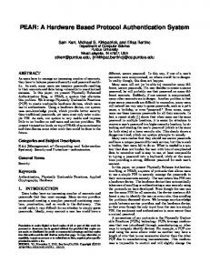
Introduction The structure of distributed electronic signature creation and verification system is presented on Fig.1 (compare [1]). The most expensive and requiring the high level of security and resiliency elements are under the full control of Signature Service Provider (SSP) and Application Provider (AP), while the signing entity has at his disposal Secure Signature Creation Device (SSCD1) only.
Application Provider (AP)
SigReq-STD
Home User’s Domain Home Users’ Domain (hSSP)
SigResp-STD
Signature Service Provider (SSP)
mSigReq-OP mSigResp-OP
SSCD-1 SSCD-2 SSCD-n
Fig.1. Three-parties functional scheme of a distributed Signature Creation System (SCS) in Home Operator Domain
It is assumed that the signing entity uses the standard PC host (his own or available in a public location) connected to the network and equipped with PIN-pad integrated with a smartcard reader; additionally he/she has at his/her disposal an appropriate smartcard with cryptocontroller (as the mobile SSCD). One of the elements of the distributed signature creation system (Fig.1) is a publicly available database of electronic document templates. This base is maintained by AP or the issuers of templates. To sign any document the signing entity should take an appropriate template from the template data base, fills it with the contents and delivers to AP in the secure manner. After the reception of the document AP verifies its compliance with the template and sends to SSP the request to init signature creation process – Standard Sign Request (SigReq-STD). SSP verifies the 1
Alternatively this role could be played by his/her mobile phone and SIM card; both together enable to establish trusted path and channel.
192
syntax and semantics of the form intended to sign, prepares Data To Be Signed (DTBS), presents them to the signing entity, and finally sends Signature Request (mSigReq-OP) to the signing entity (more precisely: to the mobile SSCD). SSCD creates the signature and returns its value to the system of SSP (mSigResp-OP). SSP formats the final form of electronic signature and returns it (SigResp-STD) to AP. The functional diagram from Fig.1 creates so called “home” domain (hSSP). One can imagine many such independent domains. With a large number of independent SSPs such a solution is cumbersome and costly; especially from AP point of view, because they have to perform registration procedure with each SSP and enter to appropriate commercial contracts. In practice, any Signature Creation Application (SCA) should provide the user the opportunity to create an electronic signature in its home domain and in visited domains as well. Such a possibility can be created if SSP can interconnect using another service (e.g. roaming services for electronic signatures) and standard interfaces. This solution significantly simplifies the operation of AP eliminating the need to register in each SSP. The trilateral functional diagram of a distributed signature creation system (presented on Fig.1) consists of the following elements: signature creation system (SCS): it enables to create an electronic signature and consists of SSCD and SCA, where o SSCD: device used for generation or usage of private key needed to create signature (the smartcard can be an example), o (mobile) signature creation application (MSCA/SCA): application within the signature creation system that allows to prepare data for signature creation; MSCA/SCA consists of two sub-applications: one functioning on the end entity side (SCA-EE) and another on the side of the signature service provider (SCA-SSP), end entity (EE): a signing entity (a signer) that creates the signature using SCA-EE application, SSP: entity enabling the generation of signatures by signing entities that authorizes and authenticates each created electronic signature cooperating with
PRZEGLĄD ELEKTROTECHNICZNY (Electrical Review), ISSN 0033-2097, R. 88 NR 10b/2012
application provider (AP), signing entity and its signature creation device (SCD), AP: entity requiring the creation of electronic signature from the signing entity. It results from above that software and hardware components of SCS are distributed between the two main participants in the system: the signing entity and the signature service provider. It is obvious that the way the distribution is done affects the functioning of the system, as well as its safety; the measure may be primarily the degree of confidence in the services provided by the system. Motivation and contribution The SCS working in distributed signature creation environment (SCE) should guarantee the security of a signing act for the signer. In practice no user is able to evaluate himself whether the system, which the signature is created in, is secure or not. Even an expert in electronic signature technology and IT security has to perform relevant investigations and tests to make such an evaluation. Therefore, the following extreme assumptions should be made: (1) a user’s computer or system has to be trusted, (2) a user’s computer or system does not need to be trusted at all. We are sure that high level of SCS security is guaranteed then and only then if SSCD locks the usage of a private key before the successful mutual authentication of crucial SCS components and SSCD. In such a case an interoperability of SSCD is limited to the relevant dedicated SCE. In further part of this paper, under the assumption that a user’s computer or system is untrustworthy, we propose a functional model of distributed signature creation application, a trusted computing base for SCS, and finally, a protocol for the authentication of software and hardware components. The proposed system enables the user to create an electronic signature if and only if the SSCD being at his/her disposal recognizes an offered SCE as a secure one and ensuring the proper protection against different threats (e.g. the malicious codes) attempting to forge electronic signatures. Structure of signature creation application (SCA) Each of the software components involved in the process of signature (e.g. [3, 4]) can be associated with SCA-EE or SCA-SSP (if this is technically feasible and acceptable in terms of functionality and security of the system). Particularly, it is relevant for three essential categories of components used in the system: components responsible for the document and attributes presentation to the signer (category P), components responsible for data to be signed preparation (category S), components responsible for SCD interaction (category D). It is possible to implement different functional models of SCA, which depend on where there are three main categories of components. If we assume (due to the adopted philosophy of building trust in a distributed system of electronic signature creation) that the trusted path and channel (see: [5]) are built between SSCD and a trusted module TRSM (at SSP side), it is worth taking into account only those models in which the components of a category D appear on SCA-SSP side, and additionally the model E as an interesting alternative for integrated application. As the result feasible models of SCA are chosen and presented in Tab.1. The components of category P, S and D can also be seen as three interrelated specialized servers (logical or
physical ones), called further appropriately server P, server S and server D, cooperating with each other, which carry all the features of the SCA. It is obvious that the proper distribution of tasks between SCA-EE and SCA-SSP, and also their proper configuration, allows to obtain any model from those presented in Tab.1. Tab. 1 – Practically feasible models of SCA Model
Part SCA-EE
Part SCA-SSP
P
S
D
P
S
D
model E
yes
Yes
yes
No
no
no
model D
yes
Yes
no
No
no
yes
model PD
no
Yes
no
Yes
no
yes
model DS
yes
No
no
No
yes
yes
model PSD
no
No
no
Yes
yes
yes
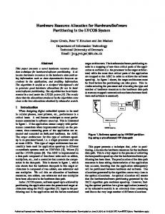
It is assumed that the server P is responsible for interactions with a user, and the server S – for interactions with an application provider. Then the server-based environment for the electronic signature creation has the form shown on Fig.2.
User
Application Provider (AP)
Server S
Server P
Server D MSCA SSCD SCS Signature Creation Environment (SCE)
Fig.2. Model of signature creation environment with servers P, S and D
Further the model DS will be considered only. In this model the server responsible for signed data and attributes presentation (server P) is implemented at the signing entity’s host and both other servers (server D and server S) – on the side of SSP. We assume that all components responsible for a secure entering of signing entity authentication data (e.g. PIN) and other secrets, and ones responsible for SSCD service, are in a hardware module SBB (it is PIN-pad or its equivalent in ATM, etc.). The basic trusted component in the system is TRSM (Tamper Resistant Security Module). From this module is derived the trust for other components of the system, especially for software and hardware components of server P (see below). Trusted computing base for SCS Trust is an intuitive concept, reflecting the degree of belief that someone or something in a particular situation is behaving as expected. The level of this belief is a measure of relationship’s certainty between the relying parties. There are three types of devices (from Fig.3) which have to act as expected: secure signature creation devices (SSCD), hardware cryptographic modules (TRSM, HSM) and PINpads (or equivalent devices intended to enter credentials in secure manner). The trust in a system, like the distributed signature creation system, cannot be built without a reliable (trusted)
PRZEGLĄD ELEKTROTECHNICZNY (Electrical Review), ISSN 0033-2097, R. 88 NR 10b/2012
193
hardware modules built into the devices listed above. Architecture of such modules can be compliant, as an example, with the proposal of Trusted Computing Group, which prepared the industrial standard for such a type of module, named Trusted Platform Module (TPM). TPM consists of components, which operate in accordance with expectations, and the trust to their performance is verified by accredited laboratories evaluating their conformance with ISO/IEC 15408 standard requirements (so called “Common Criteria”). Trust in the case of hardware modules means that they will never operate faulty, and if that happens, it will be easy to detect. This trust (further called „the base trust”) is limited to a particular module or a set of modules, and does not subject to verification (justification). However, form this trust so called “derivative trust” can be derived, which means that the trusted module can ensure reliability of another module (or group of modules, or group of software functionalities). If the trusted module determines that the reliability of another module (or group of modules, or group of software functionalities) is justified, then trust limits are extended and from that moment apply also to above checked components. The process of trust extension can be continued both based on the elements “with the base trust”, as well as on the basis of components whose trust has been verified. Justification of transitive trust in the case of new components requires to define and save within the trusted module some information allowing to extend the trust within a distributed signature creation system. This information includes Data Registration Modules (DRMs) and Cryptographic Keys Modules (CKMs). DRMs allow to store information concerning the current configuration of trusted module. This is important if the current module configuration must achieve a state in which it is possible to perform sensitive operations, such as a digital signature creation. Information concerning the current module configuration is stored in a specially protected register and associated with operations performing with the use of module (requests and appropriate responses), internal module states and parameters (constant or changing during the operation of the module). The varying states of the module, as well as the parameters, are treated as current measurements of the module integrity parameters, and for them the cumulative value of the hash function is calculated. If it is assumed that at the time ti the value of DRM is drmi, then the updated value of DRM at the time ti+1 is: (1) drmi1 h drmi ai ,
where h(...) – a cryptographic hash function, and ai – the current measurement of the module integrity parameters. The module may have more than one register, which is useful if more than one user communicate with the module. The dialogue with the module is always initiated by the user who sends an initiation request with a random challenge. The module reserves one of its register, resets its state and register value, calculates a new register initial value pcr0 based on Eq. (1), where the value of parameter a0 equals the value of random challenge sent by the user. The value pcr0 is sent back to the user, and from this moment the module and the user update its value independently, according to Eq. (1). Each module stores stationary and dynamic/transferable keys. Stationary keys are associated with its module only and cannot be sent from one module to another, nor transferred between them (even if it is possible to store them in an encrypted form outside the module). Inability to transfer stationary keys prevents their "substitution" by
194
dummy keys to simulate a real device. Dynamic/transferable keys can be transferred between modules. This occurs most often in the case of symmetric session keys that are created as a result of the successful mutual authentication of modules. There are the following keys in the trusted module: the stationary pair of asymmetric keys (DK), used for confidential communication to a module of executable code or authentication/authorizing data belonging to the owner of the module, the public key of dynamic/transferable pair of asymmetric keys (CAK), intended to ensure authenticity of executable code or authentication/authorizing data belonging to the manufacturer of the module, the stationary pair of asymmetric keys (AK), of which the private key is used for signing messages exchanged with the environment during the execution of a module authentication protocol module intended to verify its identity, the stationary pair of asymmetric keys (SK), of which the private key is used for signing data whose source of origin is the module only; particularly these data are DRMs. There are no certificates issued for public keys of type DK and CAK. It means that the private key DK (unique for each module) must be protected from disclosure, and the public key CAK must be protected from modification. A combination of keys of type CAK and DK allows for reliable loading of module manufacturer’s executable code to a given module belonging to a particular owner. The other two public keys of type AK and SK are subject to a certification process. Certificates are issued by a domain certification authority, which can be subordinate to the Root CA. The public key of the Root CA is stored within the module protected memory at the time of assigning the module its owner. In the case when keys of type AK and SK are valid for short periods of time, two different key pairs can be replaced in use by the only one pair of keys. During normal operation the module also generates additional dynamic/transferable keys, which can be shared with other trusted modules. However, the transfer of keys can be accomplished after previous mutual authentication of modules. Authentication of software and hardware components In any distributed system, whose correct operation depends on the exchange of information between its distributed components, a reliable identification of both end points of communication lines (i.e. the sender and recipient of information) should be ensured. From the perspective of the overall system security, construction and structure of the end point is just as important as the communication protocol used. It is assumed in the distributed signature creation system that the module with the base trust is always the main point of communication; through this module all messages exchanged between the system components are transmitted and received. Three key endpoints are distinguished in the distributed signature creation system (see: Fig.3): cryptographic module (TRSM) physically connected to the server D; this module is involved in each transaction of an electronic signature creation, authenticating the server P environment and authorizing the signing entity, secure signature creation device (SSCD) with installed private key used by the signing entity for secure signature creation,
PRZEGLĄD ELEKTROTECHNICZNY (Electrical Review), ISSN 0033-2097, R. 88 NR 10b/2012
SD
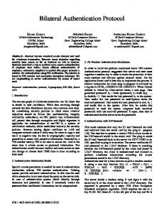
PIN-pad-like device, equipped with a keyboard for secure entry of signing entity authentication data (PIN) and other sensitive data (e.g. responses for TRSM challenges), a smartcard reader and trusted hardware module (component with possibilities similar to SSCD). It is possible, on the base of trusted components built in TRSM, SSCD and PIN-pad, to extend the trust for the whole of device, including the software responsible for device functionality. The trust constructed in this way allows to perform authentication protocols between two communication endpoints in a secure manner and to extend the trust area for each end component of this connection. Components of distributed signature creation system with four distinguished endpoints of communication lines are shown on Fig.3. These connections include communication between: trusted PIN-pad and trusted TRSM (secure connection supported by DAC component), trusted SSCD and trusted TRSM (secure path and secure channel [5] supported by DAC component), server D and server S (software SDAC components are endpoints on both sides of connection), server P and server S, supported by software PAC components.
Fig.3 Trusted path and trusted communication channels with oneway or mutual authentication
The first two connections have trusted modules in their endpoints. Therefore it is possible to build two secure connections between them and to establish the trust in this security. There are: secure communication connection PINpad_TRSM_MutualAuth between PIN-pad and TRSM, created as a result of positive completion of mutual authentication protocol compliant with ISO/IEC 9798-3 standard [8, 9]; authentication and session keys - established in this protocol – are under control of trusted PIN-pad module and TRSM, trusted path and trusted channel SmartCard_TRSM_MutualAuth between SSCD and TRSM, created as a result of positive completion of mutual authentication protocol compliant with ISO/IEC 9798-3; authentication and session keys established at the completion of authentication protocol - are under control of SSCD and TRSM. Two other connections are built without the participation of trusted hardware modules. The trust in the safety of these connections depends in this case entirely on trust in
software components PAC (servers P and S) and SDAC (servers S and D). While in the case of SDAC components (servers S and D) the trust may be justified, the justification for trust in PAC component (server P) is impossible. For this reason the following can be assumed: SDAC_SDAC_MutualAuth between server D and server S is bilaterally secure communication connection, created as a result of positive completion of mutual SSL/TLS authentication at the application level; authentication keys are installed in TRSM and HSM modules respectively; after the completion of authentication session keys are under control of SDAC components in servers D and S respectively, PAC_PAC_OneWayAuth between server P and server S is unilaterally secure communication connection, created as a result of positive completion of unilateral SSL/TLS authentication at the application level, in which server S is authenticated only; authentication keys are installed in HSM module; after the completion of authentication session keys are under control of PAC components in servers P and S respectively. Secure communication connections, trusted paths and channels are created as a result of completion of protocols with the same names. It should be noted that the presentation of a document to be signed and signature creation follows the all protocols and obtaining the state of SM (so called „secure messaging” state, which the trusted channel and path are established in). Obtaining SM state means that each of trusted system components extended its trust with two other items, what is significant because from this moment the signing entity has full guarantees that its SSCD “speaks” only to this PIN-pad, which has the card inside the reader, and only to this TRSM module, which the secure channel and path have been created with. Trusted paths, channels and secure communication connections (PINpad_TRSM_MutualAuth between PIN-pad and TRSM module, and SmartCard_TRSM_MutualAuth between SSCD and TRSM module) are built on the base of authentication keys AK and their certificates. Certificates are issued by certification authorities associated with particular SSP domain (so called – domain certification authorities), which are further denoted as CAi. CAi can be root CA for each of the domains or subordinated to one root CA. CAi and trusted modules (PIN-pads, TRSMs and SSCDs) have unique identifiers assigned to create a general identifier of the unit (OIU) in a domain managed by the i-th SSP. The structure of certificates is similar to this proposed in [7], and additionally in the case of SSCD it is so called card verifiable certificate format compliant with [11]. The mechanism of management of authentication key certificates and secure temporary replacement of those keys described in [11] allows, after establishment of CAs hierarchical structure, to transfer the trust through PIN-pad to TRSM and mutual authentication of SSCD and TRSM. The authentication protocol PINpad_TRSM_MutualAuth is presented below. The authentication protocol SmartCard_TRSM_MutualAuth is more complex, and it is the reason why it is omitted in this paper. Example of PINpad_TRSM_MutualAuth authentication protocol The basic mutual authentication protocol PINpad_TRSM_MutualAuth is performed between PIN-pad (the client) and TRSM module (the server). For the purpose of the protocol the following denotations are fixed:
PRZEGLĄD ELEKTROTECHNICZNY (Electrical Review), ISSN 0033-2097, R. 88 NR 10b/2012
195
K PINpad Manager, further called „the client”, implemented on PIN-pad side, active in mutual authentication and session keys establishment for confidentiality and integrity protection; additionally it controls communication with the server P via SBB driver and A module, A a trusted module associated with PIN-pad (e.g. SIM), T TRSM Manager (TRSM-M), further called „the server”, implemented on TRSM side, active in mutual authentication and session keys establishment for confidentiality and integrity protection; additionally it controls communication with PIN-pad via DAC component and B module, B a trusted module associated with TRSM. PINpad_TRSM_MutualAuth protocol is performed according to the following steps: 1) the server T initiates PINpad_TRSM_MutualAuth protocol, 2) the server T then instructs the cryptographic module B to generate a random challenge RB T B: generate random 3) the cryptographic module B generates the challenge RB and sends it back to the server T B T: RB 4) the server T creates a token TokenB of the form TokenB = RB || TRSM_ID, where TRSM_ID is a type OIU identifier assigned to TRSM, and it is also included in the authentication certificate of this module 5) the server T sends the token TokenB to the client K T K: TokenB 6) the client K initiates PINpad_TRSM_MutualAuth protocol and registers received information included in the token TokenB, 7) the client K then instructs the cryptographic module A to generate a random challenge RA K A: generate random 8) the cryptographic module A generates the challenge RA and sends it back to the client K A K: RA 9) the client K creates a preliminary token preTokenAB of the form preTokenAB = RA || RB || Tekst2, where Tekst2 is of the form Tekst2 = TRSM_ID and TRSM_ID is TRSM module identifier received in step 4 10) the client K sends preTokenAB to the cryptographic module A with the signature creation request K A: preTokenAB 11) the cryptographic module A calculates the digital signature sSA(preTokenAB) and sends it back to K A K: sKA(preTokenAB) 12) the client K creates a token TokenAB of the form TokenAB = RA || Tekst2 || sKA(preTokenAB) || CertPathPINpad, where CertPathPINpad is a complete certification path for PIN-pad’s certificate CertPINpad; PIN-pad is the signatory of information included in preTokenAB (or it is signed on behalf of PIN-pad); the certification path leads from PIN-pad’s certificate to the certificate of domain CAi 13) the client K sends TokenAB to the server T K T: TokenAB 14) the server T verifies TokenAB in the following way: it verifies the signature of client included in TokenAB (it includes the recovery of certification path leading from CertPINpad certificate to CA-
196
root’s public key of and the verification of all certificates included in this path), it checks if the random number RB and TRSM_ID identifier, both transferred to the client in step 5, are the same as the values included in the signed preTokenA 15) the server T next instructs its cryptographic module to generate 56 bytes of key material KAB (this key material is then used to establish three 8-bytes keys of 3DES algorithm, three 8-bytes keys of message authentication algorithm and 8 bytes of initial value for the counter used in CBC ciphering mode) T B: generate random 16) the cryptographic module B generates KAB and sends it back to the server T B T: KAB 17) the server T creates a preliminary token preTokenBA1 of the form preTokenBA1 = RB || RA || KAB || Tekst3, where Tekst3 = PIN_padID and PIN_padID is a type OUI identifier assigned to PIN-pad 18) the server T sends preTokenBA1 to the cryptographic module B with the signature creation request T B: preTokenBA1 19) the cryptographic module B calculates the digital signature sSB(preTokenBA1) and sends it back to T B T: sTB(preTokenBA1) 20) the server T then instructs the cryptographic module B to generate the third random value RC T B: generate random 21) the cryptographic module B generates RC and sends it back to the server T B T: RC 22) the server creates a preliminary token preTokenBA2 of the form preTokenBA2 = KAB || RB || RA || RC || Tekst3 || sTB(preTokenBA1) 23) the server T instructs its cryptographic module to generate 24 bytes of key KEnv (used by 3DES algorithm) T B: generate random 24) the cryptographic module B generates KEnv and sends it back to the server (a nie: client) T B T: KEnv 25) the server T sends preTokenBA2 to the cryptographic module B with a request to encipher this token using the key KEnv and 3DES algorithm T B: preTokenBA2 26) the cryptographic module B enciphers preTokenBA2 and sends it back to the server T B T: eTB(preTokenBA2) 27) the server T then creates a preliminary token preTokenBA3 of the form preTokenBA3 = KEnv || encAlgorithmID || PIN_padID, where PIN_padID is PIN-pad identifier, and encAlgorithmID is the identifier of 3DES algorithm used to encipher preTokenBA2 28) the server T sends preTokenBA3 to the cryptographic module B with the request to create an envelope with the use of client’s (PIN-pad) public key; the envelope is enciphered in OAEP mode – according to PKCS#1 recommendation [12] T B: preTokenBA3
PRZEGLĄD ELEKTROTECHNICZNY (Electrical Review), ISSN 0033-2097, R. 88 NR 10b/2012
29) the cryptographic module B creates the envelope env(preTokenBA3) and sends it back to the server T B T: env(preTokenBA3) 30) the server T creates the token TokenBA of the form TokenBA = PIN_padID || encAlgorithmID || len_eTB || eTB(preTokenBA2) || lenEnv || env(preTokenBA3) || CertPathTRSM, where CertPathTRSM is a complete certification path for the certificate CertTRSM, PIN_padID is PINpad identifier, encAlgorithmID is an identifier of enciphering algorithm used to encrypt preTokenBA2, len_eTB – the length of the ciphertext eTB(...) in nbytes, and lenEnv is the length of envelope env(...) in bytes. 31) the server T sends TokenBA to the client K T K: TokenBA 32) the client K decrypts the envelope firstly, then it checks PIN_padID and, if it is proper one, decrypts TokenAB using the enciphering algorithm with encAlgorithmID identifier; for the purpose of token verification the following is performed: verification of the server’s signature included in TokenieBA (it includes the recovery of certification path leading from CertTRSM certificate to CA-root’s public key of and the verification of all certificates included in this path) checking if the random number RB, transferred to the client in step 5, is the same as the values included in the signed tokens preTokenBA1 and preTokenBA2 checking if the random number RA, transferred to the server in step 13, is the same as the value included in the signed token preTokenBA checking if PIN_padID identifier is its own identifier 33) the client K creates a preliminary preTokenABA of the form preTokenABA = RC || SecretSessionID || TRSM_ID, where SecretSessionID is a secret session identifier, and encrypts this token using the session key determined on the base of key material KAB, TokenABA = eKK(preTokenABA) 34) the client K sends TokenABA to the server T K T: TokenABA When the protocol PINpad_TRSM_MutualAuth is completed, the client (PIN-pad) and the server (TRSM) share a confidential key material KAB (including the counter, which can be used for the numbering of packets sent between the parties). On the base of key material both parties create session keys for messages encryption and authentication. Since the establishment of session keys further exchange of data between PIN-pad and TRSM is performed in a confidential manner (requests/responses frames are encrypted). 4. Conclusions The concepts of trusted modules presented in the paper and authentication protocols designed on that base have been implemented by Unizeto Technologies S.A. in the system proCertum dE-Signature. These protocols unit together with the hardware and software components constitute a reliable calculation basis for the whole system of secure signature creation. This ensures that the operating of proCertum dE-Signature must be preceded by a mutual authentication between PIN-pad-like device and
TRSM, and between SSCD and TRSM, and that after the signing entity call of the proper stage of signature creation further implementation of the protocol depends on the successful completion of mutual authentication between SSCD and TRSM. The security of authentication protocols has been the subject of formal analysis performed by a team from the Technical University of Gdansk. This analysis confirmed the resistance of protocol against known attacks specific for this type of protocols (see [13, 14, 15]). Wydanie publikacji zrealizowano przy udziale środków finansowych otrzymanych z budżetu Województwa Zachodniopomorskiego. REFERENCES [1] ETSI TR 102 203 Mobile Commerce (M-COMM) - Mobile Signatures - Business and Functional Requirements, V1.1.1 (2003-05), Technical Report [2] TCG Specification Architecture Overview Specification, Revision 1.2, 28 April 2004, [3] CEN CWA 14170 Security Requirements for Signature Creation Applications, July 2001 [4] ETSI TR 102 206 Mobile Commerce (M-COMM) - Mobile Signature Service - Security Framework, V1.1.3 (2003-08), Technical Report [5] Dz.U. 2002 nr 128 poz. 1094 Rozporządzenie Rady Ministrów z dnia 7 sierpnia 2002 r. w sprawie określenia warunków technicznych i organizacyjnych dla kwalifikowanych podmiotów świadczących usługi certyfikacyjne, polityk certyfikacji dla kwalifikowanych certyfikatów wydawanych przez te podmioty oraz warunków technicznych dla bezpiecznych urządzeń służących do składania i weryfikacji podpisu elektronicznego (in Polish) [6] Brickell E., Camenisch J., Chen L., Direct anonymous attestation, in Proceedings of 11th ACM Conference on Computer and Communications Security, ACM Press, 2004 [7] EMV2000 Integrated Circuit Card Specification for Payment Systems: Book 2 - Security and Key Management, Version 4.0, December, 2000 [8] RFC 3163 ISO/IEC 9798-3 Authentication SASL Mechanism, August 2001 [9] ISO/IEC 9798-3:1998 Information technology -- Security techniques -- Entity authentication -- Part 3: Mechanisms using digital signature techniques [10 ISO/IEC 9796-2 Information technology -- Security techniques - Digital signature schemes giving message recovery -- Part 2: Integer factorization based mechanisms [11] EN 14890-1:2008 Application interface for smart cards used as secure signature creation devices. Basic services, December 2008 [12] PKCS #1: RSA Cryptography Standard RSA Laboratories, v.2.1, June 14, 2002 [13] Olszewski M., A model-based approach to analysis of security protocols. a case study, in TEHOSS 2005: IEEE International Conference on Technologies for Homeland Security and Safety, Proceedings: Gdansk, Poland, September 28-30, 2005, Gdansk Univ. Technol. 2005, pp. 221-226 [14] Jakubowska G., Dembiński P., Penczek P., Szreter M., Simulation of Security Protocols based on Scenarios of Attacks, Fundamenta Informaticae, Vol. 93 n.1-3, pp.185-203, January 2009 [15] Olszewski M., Cyra Ł., An integrated framework for security protocol analysis, Proceedings of the 2008 ACM symposium on Information, computer and communications security, March 1820, 2008, Tokyo, Japan
Authors: Jerzy Pejaś, PhD eng., Imed El Fray, PhD eng. West Pomeranian University of Technology in Szczecin, Faculty of Computer Science and Information Technology, e-mail: {jpejas, ielfray}@wi.zut.edu.pl; Andrzej Ruciński, Unizeto Technologies S.A., Szczecin.
PRZEGLĄD ELEKTROTECHNICZNY (Electrical Review), ISSN 0033-2097, R. 88 NR 10b/2012
197