(i) compact the layout and nd the con ict graph; (ii) nd the minimum set of edges ..... exactly one vertex from Odd, which we call the center of the Voronoi region,.
Automated Layout and Phase Assignment Techniques for Dark Field Alternating PSM Andrew B. Kahng, Huijuan Wang and Alex Zelikovsky UCLA Department of Computer Science, Los Angeles, CA 90095-1596 fabk, huijuan, alexz g @cs.ucla.edu http://vlsicad.cs.ucla.edu
ABSTRACT
We describe new, e�cient algorithms for layout modi cation and phase assignment for dark eld alternating-type phase-shifting masks in the single-exposure regime. We make the following contributions. First, we give optimal and fast algorithms to minimize the number of phase con icts that must be removed to ensure 2-colorability of the con ict graph. These methods can potentially reduce runtime and/or improve solution quality, compared to previous approaches of Moniwa et al. and Ooi et al. Second, we suggest a new iterative 2-coloring and compaction approach that simultaneously optimizes layout and phase assignment. The approach iteratively performs the following steps: (i) compact the layout and nd the con ict graph; (ii) nd the minimum set of edges whose deletion makes the con ict graph bipartite; and (iii) add a new compaction constraint for each edge in this minimum set, such that the corresponding pair of features will no longer con ict. Third, we describe additional approaches to co-optimization of layout and phase assignment for alternating PSM. Preliminary computational experience appears promising. Keywords: Layout veri cation, manufacturability, alternating phase-shift mask (PSM), compaction, physical design, yield enhancement
1. INTRODUCTION
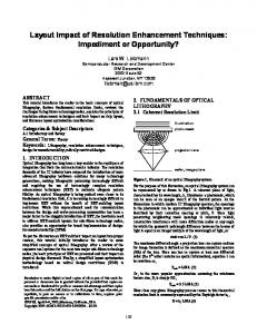
Phase-shifting mask (PSM) technology enables the clear regions of a mask to transmit light with prescribed phase shift. Consider two adjacent clear regions with small separation, and respective phase shifts of 0 and 180 degrees. Light di�racted into the nominally dark region between the clear regions will interfere destructively; the improved image contrast leads to better resolution and depth of focus. All PSM variants employ this basic concept, which was proposed by Levenson et al. in 1982 (see Figure 1). Our work, like that of Moniwa et al. and Ooi et al., pertains to the dark eld, alternating (or Levenson-type) phase-shifting mask technology with negative photoresist. In particular, we seek methods compatible with single-exposure alternating PSM. As in previous work, we use the positive constants to de ne a simpli ed relationship between printability and the distance between two clear regions. The distance between any two features cannot be smaller than without violating the minimum spacing design rule. If the distance between two features is at least but smaller than , the features are in phase con ict.� Phase con ict can be resolved by assigning opposite phases to the con icting features. In other words, de nes the minimum spacing rule when two features have the same phase. If the distance between two features is greater than , there is no phase con ict and the features can be assigned arbitrary phases. Note that the values of and are layer-dependent. We also let � denote the minimum allowed width of any feature on the layer of interest. Finally, we assume that all features are rectilinearly oriented (axis-parallel) polygons. 6
11
8,9
11,12
b < B
b
b
B
B
B
b
B
w
b
The Phase Assignment Problem: Given a layout, assign phases to all features such that no two con icting features are assigned the same phase.
Research at UCLA was supported by a grant from Cadence Design Systems, Inc. precisely, two features are in phase con ict if (i) there is no pair of points, one from each feature, whose separation is less than b; and (ii) there is some pair of points, one from each feature, whose separation is less than B . � More
Conventional Mask
Phase Shifting Mask Glass Chrome Phase Shifter
Apertures
0 E at mask 0
E at wafer
0
I at wafer
0
(a)
(b)
Figure 1. Comparison of di�raction optics of conventional and phase-shifting masks. denotes electric eld and denotes intensity. With the conventional mask (a) light di�racted by two adjacent apertures constructively interferes, increasing the light intensity in the dark area of the wafer between the apertures. With the phase-shifting mask (b), the phase shifter reverses the sign of the electric eld, and destructive interference minimizes light intensity at the wafer in the dark area between apertures. E
I
1.1. The Con ict Graph
For a given layout of polygonal features, the con ict graph = ( ) is constructed by de ning a vertex for each feature, and introducing an edge between two vertices exactly when the corresponding features are in phase con ict. The con ict graph can be constructed in ( log ) time, where is the total number of segments in all polygon boundaries.y In alternating PSM, we can remove all phase con ict by assigning opposite phases to each pair of adjacent vertices in the con ict graph . This is equivalent to 2-coloring the vertices of with phase 0 and phase 180. For this to be possible, must be bipartite, i.e., have no odd cycles. Hence, if the con ict graph is not bipartite, our goal is to delete enough edges such that no odd cycles exist in the remaining modi ed con ict graph. Edge deletion in the con ict graph is achieved by changing the placement of layout features so that they no longer con ict. E�cient algorithms that we give below for removing odd cycles depend on planarity of , an assumption that we now justify. Theorem 1. Assume that (i) the minimum feature size satis es � , (ii) 2 � and (iii) four rectangles which are pairwise (with the possible exception of one pair) in con ict do not have diagonal con icts (see Figure 2(a)). Then, the con ict graph is planar. Proof sketch. For each feature, locate a representative node arbitrarily within this feature. For any two features in con ict choose a pair of closest points on their boundaries and connect each of these points to the other and the the representative node of its respective feature (see Figure 2(b)). In other words, each con ict edge is subdivided into two connections inside features and an outside segment between features. This subdivision does not a�ect planarity. For each feature, the connections between its representative node and all points on the boundary can be routed G
O n
n
V; E
n
G
G
G
G
G
w
w
b
b
B
G
yA
standard construction is as follows. Slice each feature (polygon) into rectangles by vertical cuts through all polygon vertices, maintaining a pointer from each rectangle to its containing polygon. � Bloat each rectangle by distance B=2. � Using sweepline and interval trees, detect con icts between polygons by nding overlapping pairs of rectangles that belong to di�erent polygons. Alternatively, one may detect intersections of bounding boxes of polygons, then check whether the corresponding polygons actually intersect. �
>B
outside segments
connections
w
111 000 0000 0000 1111 0001111 111 0000 1111 0000 1111 000 111 0000 1111 0000 1111 00 11 0001111 111 0000 0000 1111 00 11 00 11 00 11 00 11
b
b
11 00 000 00111 11 000 111
Figure 2. (a) We assume that there are no con icts between diagonal pairs (dashed edges) in a set of four features if at least three other con icts exist. (b) The subdivision of edges of the con ict graph. (c) There is no con ict between the left feature and the right feature because � 2 . B
b
without intersections. Any outside segment is shorter than , therefore, no outside segment can go into a feature and then leave it because it would then have length at least 2 � (see Figure 2(c)). Thus if two con ict edges intersect, their outside segments intersect outside of features. Suppose that ( ) and ( ) are two intersecting outside segments. Assume rst that two points, say and , belong to the same feature. Because ( ) and ( ) intersect, j j + j j j j + j j. Therefore, either ( ) is longer than ( ) or ( ) is longer than ( ), which contradicts the de nition of the outside segment as a closest pair. If all four points belong to di�erent features, then it can be shown that three pairwise distances other than ( ) and ( ) between these four points are smaller than , which contradicts assumption (iii). B
b
a; b
c; d
a
a; b
a; d
a; b
B
c; d
c; d
a; b
c; d > a; d
b; c
b
a; b
c; b
c; d
B
1.2. Outline of the Paper
The remainder of this paper is organized as follows. In Section 2, we review previous approaches to edge deletion in con ict graphs, and then suggest several improvements as well as new approaches. In Section 3 we describe an optimal algorithm for odd cycle elimination; we also describe a fast algorithm based on the Voronoi graph concept. Section 4 describes the implementation of two proposed methods. We conclude with computational experience and directions for future work.
2. APPROACHES TO REMOVING ODD CYCLES FROM THE CONFLICT GRAPH 2.1. Previous Work Moniwa et al. and Ooi et al. rst posed the phase assignment problem and suggested methods of detecting cases when there is no valid phase assignment, i.e., when the con ict graph contains odd cycles. Subsequently, Ooi et al. and Moniwa et al. suggested interactive methods which fully exploit information in the mask layout. The heuristic of Moniwa et al. rst constructs the con ict graph , then creates a list of all odd cycles in using an enumerative approach. The heuristic then iteratively nds and deletes the edge that is in the greatest number of minimum-length odd cycles. Deletion is accomplished by increasing the lower bound on separation between the corresponding features, and then applying a compactor to perturb the shape or position of these features (see Figure 3). This approach may be feasible for the cell layout editing context, but likely does not scale to large instances since the number of odd cycles can be exponential in the size of the layout. Moreover, the heuristic does not necessarily delete the minimum number of edges, nor will it necessarily select edges whose deletion will have minimum impact on the layout. Ooi et al. also suggested a compaction-based method which (i) produces a symbolic layout from the mask layout; (ii) performs phase assignment in the symbolic layout; and (iii) compacts the symbolic layout using minimum spacing design rules consistent with the phase assignment. The advantage of the compaction-based method is that it is fully automated and guarantees to remove all odd cycles from the con ict graph. On the other hand, the phase assignment step is relatively oblivious to details of the mask layout; the ensuing compaction step may not minimize distortion of the original layout. 8
12
11
9
9
12
G
G
Vias
>B
B
Figure 3. Changing a shape without changing positions of vias.
2.2. Proposed Methods
We propose the following approaches to layout modi cation and phase assignment for alternating PSM. Iterative coloring and compaction. Our rst new approach generalizes the approaches of Ooi et al. and Moniwa et al. Initially, we constrain the layout only by the minimum-spacing design rule, i.e., no two features can be less than distance apart. We then iteratively apply the following three steps until the con ict graph becomes bipartite: 12
9
b
G
(i) compact the layout and nd the con ict graph ; (ii) nd the minimum set of edges whose deletion makes the con ict graph 2-colorable; and (iii) add a new constraint for each edge in this minimum set, such that the pair of features connected by this edge must be separated by distance at least ; G
G
B
\One-shot" phase assignment. This is an improvement over the method in Ooi et al. It consists of the following 12
steps: (i) nd the con ict graph ; (ii) nd the minimum set of edges whose deletion makes the con ict graph 2-colorable; (iii) assign phases such that only the con ict edges in the minimum set connect features of the same phase; and (iv) compact the layout with \PSM design rules", i.e., minimum separation between features that are assigned the same phase, and minimum separation between features that are assigned di�erent phases. Splitting. Our third proposed method \splits" su�ciently long features into several parts; this is equivalent to splitting one vertex into several parts in the con ict graph. Introducing partial shifters between these parts allows gradual transitions between 0-phase and 180-phase with no dark edge being formed. Such approaches are used for bright eld PSM with positive photoresists. In the context of dark eld with negative photoresists, splitting allows us to assign di�erent phases to neighboring parts within the same feature.z Notice that if we assign the same phase to neighboring parts of a given feature, we save the cost of the partial shifters between the parts, since no transition is needed. The splitting technique requires a more complicated mask, but has two advantages: (i) it can only decrease the number of odd cycles, and (ii) it does not perturb the layout geometry. Figure 4 shows how splitting can eliminate odd cycles. Splitting can be implemented via an optional preprocessing of that splits vertices corresponding to long features into several disconnected vertices. Spacing. Our next suggestion is to widen the layout at selected coordinates, by inserting vertical or horizontal gaps along the whole layout (see Figure 5). Inserting a gap has the e�ect of deleting all edges of the con ict graph that cross the gap. We observe that if one has already identi ed a set of edge deletions that will remove all odd cycles from , we can nd the minimum number of spacings that will delete these edges. The entire layout can be represented as a 0-1 matrix in which 1's are placed in all the con ict areas corresponding to desired edge deletions. Each column or row in the matrix corresponds to a gap to be introduced. We can nd the minimum number of columns and rows that cover all 1's by applying an ( ) algorithm for minimum matching in bipartite graphs. G
G
B
b
G
G
G
O n
1:5
z Partial shifter technology that allows 60-, 120- or 180-degree phase shifting has been reported by AMD.10 The technology is \free" in the sense that 180-degree phase shifters are in any case built out of several layers of 60-degree phase shifters. Such a mask technology reduces defects because it imposes a \voting" regime: a defect that causes a phase edge or otherwise a�ects the printed image must occur at the same location in two out of the three 60-degree layers.
Figure 4. Splitting a long feature may result in odd cycle elimination. The phase is shifted between 0 and 180 degrees in the shaded areas, using partial shifter techniques.
gap conflicts
Figure 5. Resolving multiple con icts between features by introducing a gap. Layer assignment. Finally, we suggest the use of layer assignment to remove phase con icts, as shown in Figure 6. This is a key degree of freedom that is natural for a routing tool, but unnatural for current mask optimization tools that view a given layer's geometries as immutable. With layer assignment, a problematic wire feature can, quite literally, be replaced by two vias and then transferred to another layer. Of course, such an approach does not apply to device layers.
other layer vias
Figure 6. Resolving con icts by moving the middle wire to another layer.
2.3. Edge Weights in The Con ict Graph
In general, when an optimal phase assignment is found, each con ict edge that separates two same-phase features induces a minimum spacing requirement of between the features. Such a requirement is passed to compaction in the form of a spacing constraint. To fully exploit compaction technology and achieve optimal algorithms for phase assignment with minimum layout distortion, we may assign di�erent weights to di�erent con ict edges. With the B
methods for optimal odd cycle removal that we develop below, even if the con ict edges have di�erent weights it is still possible to nd the minimum-weight set of con ict edges whose deletion makes the con ict graph bipartite. During compaction we may detect spacing constraints (between feature pairs) that are on critical paths, i.e., constraints that when increased will directly increase the size of the layout. We propose to assign larger weight to con ict edges corresponding to such constraints; lesser weight should be assigned to con ict edges that do not lie on critical paths (see Figure 7). Finally, we observe that several methods to delete edges and eliminate odd cycles can be combined. Then, the weight of a given con ict edge should re ect the minimum possible cost of breaking that edge using any of the available methods.
111 000 000 111 000 111 000 111 000 111 000 111 000 111 000 111
11111111 00000000 00000000 11111111 00000000 11111111 00000000 11111111
111111 000000 000000 111111 000000 111111 000000 111111 000000 111111 000000 111111 000000 111111 000000 111111 000000 111111
111 000 000 111 000 111 000 111 000 111
Figure 7. Critical path between leftmost and rightmost features consists of thick edges. Thin edges on non-critical paths may be broken for free.
3. OPTIMAL AND FAST ALGORITHMS FOR ODD CYCLE ELIMINATION IN CONFLICT GRAPHS
We now present optimal and fast algorithms for nding the minimum-cost set of con ict edges whose deletion eliminates all odd cycles.
The Minimum Distortion Problem: Given a planar graph = ( ) with weighted (multiple) edges, nd the minimum weight edge set such that the graph ( ? ) contains no odd cycles. G
M
V; E
V; E
M
3.1. Optimal Algorithm
Hadlock and Orlova et al. proposed the rst exact algorithm for odd cycle elimination. 2
13
Theorem 2. The Minimum Distortion Problem can be solved optimally in polynomial time. Proof sketch. To eliminate all odd cycles it is su�cient to eliminate odd faces of the planar graph (see Figure 2,13
G
8). Consider a graph that is the geometric dual of : all faces of are vertices of (note that there is a vertex of that corresponds to the \outer face" of ), and each edge of intersects with exactly one edge of . The odd faces of correspond to odd-degree vertices of . Any edge elimination in corresponds to edge contraction in ; in particular, we may remove a pair of odd faces from by contraction edges of a (minimum-weight) path between the corresponding odd-degree vertices in . Hence, the minimum distortion set corresponds to minimum weight matching of odd-degree vertices in , which can be found in polynomial time. D
G
D
G
G
G
D
D
G
D
G
D
G
D
D
3.2. Fast Algorithm
The main drawback of the Hadlock and Orlova et al. algorithm is that nding all pairwise distances between odd-degree vertices in is too time- and memory-consuming. We now propose a new fast approach based on the Hadlock and Orlova et al. algorithm, but modi ed using the Voronoi graph paradigm of Mehlhorn. It consists of the following steps: D
7
1. Build a graph 0 which is the geometric dual of . Each vertex in 0 corresponds to a face in . Each edge 0 between two vertices of 0 corresponds to (i.e., \crosses") the edge that separates the two corresponding faces in . The weight of an edge 0 in 0 is equal to the weight of the corresponding edge in . G
e
G
G
G
G
G
e
e
G
e
G
1 0 0 00 0 1 1 0 11 1 00 11 0 1 00 11 0 1 0 1 0 1 000 111 0 1 0 1 0 1 00 11 01 1 0 0 0 10111 0001 0 1 0 0 1 1 01 1 00 11 0 1 00 11 0 1 00 0 11 00 1 11 01
(b)
(a)
0 1 1 0 0 0 1 1 0 1 00 11 00 11 0 11 00 0 1 00 11 11 00 11 1 00 0 1 0 1 0 1 00 0 11 1
(c)
1 0 0 1 1 0 0 1 (e)
(f)
(d)
Figure 8. From the con icts between features (a), the con ict graph is derived (b). The dual graph (c) is constructed.
The vertices of odd degree are matched using paths in the dual graph (d), and the corresponding con ict edges are determined (e). Finally, the minimum set of con icts to be deleted is determined (f). 2. Observe that faces of that are de ned by an odd number of edges correspond to the odd-degree vertices of 0 . We use to denote this set of vertices in 0 . Partition all vertices of 0 into the Voronoi regions of the vertices in , such that: (i) each Voronoi region contains exactly one vertex from , which we call the center of the Voronoi region, and (ii) each even-degree vertex belongs to the Voronoi region whose center is the closest according to shortest-path distance (break ties arbitrarily). 3. Construct the Voronoi graph ( 0 ) in which each vertex represents a Voronoi region, and two vertices and are adjacent if a shortest path in 0 between the corresponding region centers is completely contained in the two regions (see Figure 9). G
G
Odd
G
G
7
Odd
Odd
V or G
R2
R1
G
2
Voronoi regions
Figure 9. The geometric dual graph
(left) and the Voronoi graph of its odd-degree vertices (right). The weight of an edge in ( ) is the total cost of edges in the shortest path (dashed edges) between the centers of the Voronoi regions (black vertices). V or
0 G
G
0
4. Find a minimum weighted matching in ( 0 ). 5. Find edge sets in that correspond to paths in 0 , which in turn correspond to the edges of the minimum weighted matching in ( 0 ). These are the edges to be deleted in the con ict graph. V or G
G
G
V or G
Step 1 can be performed in time ( ), where is the number of features. Construction of ( 0 ) requires time ( log ). Step 4 requires time (j j )), and Step 5 can be done in time ( ). Thus, the total runtime of our algorithm is ( log + j j ). O n
O n
n
O
O n
n
Odd
Odd
n
2
V or G
O n
2
4. IMPLEMENTATION EXPERIENCE
We have implemented the \one-shot" and \iterative" methods from Section 2.2; other proposed methods are in earlier stages of investigation. The ows for the one-shot and iterative methods are shown in Figure 10. Read layout
Read layout
Construct conflict graph
Construct conflict graph
Find minimum set of deleted edges in conflict graph
Find minimum set of deleted edges in conflict graph
Assign phases Generate connectivity and spacing constraints according to phases (x-, y-directions separately) Solve constraint graph with Bellman-Ford (x-, y-directions separately)
If minimum set is empty, output layout Generate connectivity and spacing constraints according to phases (x-, y-directions in alternation)
Output layout
Solve constraint graph with Bellman-Ford (x-, y-directions in alternation)
(a) One-Shot Method
(b) Iterative Method
Figure 10. Flows for the \one-shot" and iterative methods. Note that the one-shot approach applies compaction separately in the - and -directions to enforce the given phase assignment. The iterative approach alternates between - and -compaction, and recomputes the minimum set of deleted con ict edges (and resulting compaction constraints) after each compaction. x
x
y
y
4.1. Software Implementation
Our system has been implemented in C++ on the Solaris 2.6, Sun CC 4.2 platform. Input is (hierarchical) GDSII that is converted to CIF, then read into an internal polygon database. There are two major software elements.
� The phase generator nds a minimum-cost set of con ict edges for deletion, induces a phase assignment, and
generates compaction constraints such that the layout remains consistent with the phase assignment. The code for fast minimum-cost odd cycle elimination uses an imported C code for maximum weighted matching in a general graph, implementing the algorithm of Gabow (1973) and written by Edward Rothberg, which we obtained by anonymous ftp from dimacs.rutgers.edu.
In the one-shot ow, the phase generator creates compaction constraints as follows: if two features are assigned di�erent phases, they have minimum separation ; otherwise, they have minimum separation . In the iterative
ow, constraints are speci ed only for pairs of features corresponding to broken con ict edges. � The graph-based compactor (i) generates constraints between feature edges according to standard design rules and an e�cient sweepline approach, (ii) adds constraints produced by the phase generator, and (iii) stores all constraints as edges of a constraint graph. The compactor then applies the Bellman-Ford algorithm to solve the constraint graph, i.e., obtain optimal -coordinates of all edges of all features. Our implementation generally follows the description of leaf-cell compaction given by Bamji and Varadarajan. We consider three types of constraints: (i) shape constraints x the shape of features which cannot be changed according to design rules; (ii) overlap constraints ensure that features will remain electrically connected after compaction, and/or properly aligned between di�erent layers; and (iii) spacing constraints enforce separation design rules (including PSM-speci c separation rules between features of the same or of the di�erent phase). Note that we perform -compaction the same way that we do -compaction (after temporarily swapping and coordinates). In the one-shot ow, we output the new positions of all features after compacting in and directions. In the iterative ow, we return control to the phase generator and continue the iteration until we obtain a valid phase assignment for all features. b
B
x
1
y
x
x
y
x
y
4.2. Computational Experience
Table 1 summarizes our computational experience with seven layouts of di�erent sizes and densities. All layouts were derived from industry standard-cell layouts. All runtimes are CPU seconds on a 300 MHz Sun Ultra-10 workstation with 128MB RAM, except for Layout 7 results, which are CPU seconds on a 140MHz Sun Ultra-1 with 320MB RAM. We see that our code can handle very large at designs in reasonable time. Test Layout1 Layout2 Layout3 Layout4 Layout5 Layout6 Layout7 # polygons 3769 6914 9778 13796 18252 22954 36227 # rectangles 4549 8691 12971 18325 24255 30625 36227 # nodes 4549 8691 12971 18325 24255 30625 36227 con ict graph # edges 15204 12204 38342 55194 74924 97488 160400 runtime 1 88 1 40 4 76 7 15 19 85 27 22 19 99 # nodes 3250 1650 7348 10634 14642 19341 36926 dual graph # edges 10530 2516 20292 30044 42026 56602 82962 runtime 4 45 0 23 10 12 19 02 80 41 133 75 42 63 # nodes 934 0 1378 2046 2898 3968 2764 Voronoi graph # edges 3232 0 4164 6430 9430 13328 7064 runtime 0 06 0 0 09 0 15 0 47 0 68 0 18 Matching size 1402 0 2562 3529 5197 7289 5672 runtime 11 0 26 1 79 4 91 22 68 63 67 5 96 :
:
:
:
:
:
:
:
:
:
:
:
:
:
:
:
:
:
:
:
:
:
:
:
:
:
:
Table 1. Computational results for phase assignment of layouts with various sizes. In conclusion, we have suggested new, e�cient and optimal algorithms for minimum-cost layout perturbation and con ict elimination in the dark eld (negative photoresist, single exposure) alternating PSM context. Our approach has been integrated with a GDSII reader, polygon database and layout compactor. Our preliminary computational tests show that our code can assign phases to comparatively large designs in reasonable time. Other, potentially more powerful approaches to layout modi cation and phase assignment for alternating PSM are currently under investigation.
ACKNOWLEDGMENTS
We thank P.K. Vasudev for introducing the topic of phase-shifting masks to us in April 1997. We are also grateful to Frank Schellenberg for guidance and encouragement over the past year. Andrew Caldwell, Igor Markov and Devendra Vidhani provided critical assistance in our software development.
REFERENCES
1. C. Bamji and R. Varadarajan, Leaf Cell and Hierarchical Compaction Techniques, Kluwer Academic Publishers, Boston, 1997. 2. F. O. Hadlock, \Finding a Maximum Cut of a Planar Graph in Polynomial Time", SIAM J. Computing 4(3) (1975), pp. 221-225. 3. A. B. Kahng, G. Robins, A. Singh, H. Wang and A. Zelikovsky, \Filling and Slotting : Analysis and Algorithms", Proc. ACM/IEEE Intl. Symp. on Physical Design, 1998, pp. 95-102. 4. A. B. Kahng, G. Robins, A. Singh and A. Zelikovsky, \Filling Algorithms for Layout Density Control", manuscript, April 1998. 5. A. B. Kahng and H. Wang, \Toward Lithography-Aware Layout: Preliminary Litho Notes", manuscript, July 1997. 6. M. D. Levenson, N. S. Viswanathan and R. A. Simpson, \Improving Resolution in Photolithography with a Phase-Shifting Mask", IEEE Trans. on Electron Devices ED-29(11) (1982), pp. 1828-1836. 7. K. Mehlhorn, \A Faster Approximation Algorithm for the Steiner Problem in Graphs", Information Processing Letters 27 (1988), pp. 125-128. 8. A. Moniwa, T. Terasawa, N. Hasegawa and S. Okazaki, \Algorithm for Phase-Shift Mask Design with Priority on Shifter Placement", Jpn. J. Appl. Phys. 32 (1993), pp. 5874-5879. 9. A. Moniwa, T. Terasawa, K. Nakajo, J. Sakemi and S. Okazaki, \Heuristic Method for Phase-Con ict Minimization in Automatic Phase-Shift Mask Design", Jpn. J. Appl. Phys. 34 (1995), pp. 6584-6589. 10. J. Nistler, G. Hughes, A. Muray and J. Wiley, \Issues Associated with the Commercialization of Phase Shift Masks", SPIE 11th Annual BACUS Symposium on Photomask Technology, SPIE 1604 (1991), pp. 236-264. 11. K. Ooi, S. Hara and K. Koyama, \Computer Aided Design Software for Designing Phase-Shifting Masks", Jpn. J. Appl. Phys. 32 (1993), pp. 5887-5891. 12. K. Ooi, K. Koyama and M. Kiryu, \Method of Designing Phase-Shifting Masks Utilizing a Compactor", Jpn. J. Appl. Phys. 33 (1994), pp. 6774-6778. 13. G. I. Orlova and Y. G. Dorfman, \Finding the Maximum Cut in a Graph", Engr. Cybernetics 10 (1972), pp. 502-506.