Automated Realization of * Business Workflow Specification 4†
Guohua Liu
3†
Xi Liu
1
2†
Haihuan Qin Jianwen Su
1,5
Zhimin Yan
1,5
Liang Zhang
1
School of Computer Science, Fudan University, China Department of Computer Science, Univ. of California at Santa Barbara, USA 3 Department of Computer Science & Technology, Nanjing University, China 4 Department of Computer Science & Engineering, Yanshan University, China 5 Fudan-HangZhou Joint Lab. of Digital Real Estates 2
[email protected],
[email protected],
[email protected],
[email protected],
[email protected],
[email protected]
Abstract. Business workflow assembles together a collection of tasks or activities in order to accomplish a business objective. Management of business workflows is facing many significant challenges, including in particular design, making changes, interoperations, etc. A key step in addressing these challenges is to develop techniques for mapping logical workflow specifications into executable workflow systems. In this paper we introduce a new artifact-centric workflow model called Artifact Conceptual Flow (ArtiFlow) and show that automated translation from ArtiFlow to BPEL is achievable. We also discuss technical issues in the translation.
1
Introduction
A business workflow assembles together a collection of tasks or activities in order to accomplish a business objective. It is a natural extension of the production pipeline concept. The goal of business process management (BPM) is to support design, execution, evolution (making changes) of a large number of inter-related business workflows [12] with the same or different schemas. While the BPM problems are not new, they have received significantly increasing interest from research communities over the last decade, due to the rapidly widespread use of computing devices and Internet technology. Indeed, “digitizing” documents and processes has made business workflow to operate effectively and more efficiently. The demand on underlying software systems for managing the digitalized versions has increased significantly. As a result, software systems become much more complex. However, software research has not yet developed mature technology for software system design and management in general and business workflow software in particular. Significant challenges are facing the business workflow application communities in many aspects of business * †
Work supported in part by US NSF grants IIS0145195, CNS0613998, and IIS0812578; and also by NSF of China grant 60873115, the National Basic Research Program (973) grant 2005CB321905. Part of work done while visiting School of Computer Science, Fudan University.
G. Liu, X. Liu, H. Qin, J. Su, Z. Yan, and L. Zhang
workflow management
data management
2
Fig. 1. Automated realization: databases vs. business workflow
workflow, including in particular, design, evolution, interoperation [8]. Technical difficulties include: (1) business process models used by the business managers are drastically different from executable workflows IT engineers develop and maintain, (2) key business performance indicators (KPIs) are hard to, (3) it is extremely difficult to change existing workflows according to the changes made to the corresponding business models, and (4) there is a lack of tools and support for business workflow interoperation. In addition, there are also significant barriers caused by differences between disciplines (business vs. IT) and between cultures (clients vs. managers). In this paper, we make three position statements that outline a general approach for developing necessary technology for BPM challenges. Statement 1: Automated or semi-automated realization of business workflow specifications is the key issue in tackling BPM challenges. Business workflow design starts with modeling to specify how the workflow should function. This step is important and usually done by business managers. The subsequent step is to turn the specification into an executable workflow. In this paper, we refer to this process of turning a business workflow specification into executable workflow as “realization”. Currently, realization is a labor-intensive task and often done in an ad hoc manner. Figure 1 (right) illustrates the two steps. In particular, workflow management happens at the software systems level. But it does not have to be the case. We consider the evolution of database systems as a comparison. Prior to the mid 70’s, mapping logical database design to physical implementation was mostly done by hand. The resulting system naturally embedded many human decisions. The arrival of relational DBMSs in the 70’s brought automation to the design process with a suite of techniques including query optimization, physical data design, etc. (Figure 1, left). Automation of realization means systematic physical design that allows one to address data management problems at the conceptual level rather than implementation level. Figure 1 illustrates a similarity between database and business workflows. Both have the steps of logical designs and physical realizations. The ad hoc nature of workflow realization makes it hard to reason about and maintain workflow systems, and make needed changes. We argue that automated translation of logical workflow
Automated Realization of Business Workflow Specification
3
specification into executable systems will provide a significant help to business workflow management. Statement 2: Artifact-centric models are most suitable for automated realization. In particular, the correspondence between logical models and executable workflows makes it easier to do BPM, in particular, handle KPI and modifications. Automating workflow realization is not easy. Traditional workflow modeling languages emphasize tasks (or activities) and the control flow. The lack of modeling data early makes it impossible to automate realization, since the logical specification concerns only “structural constraints” (tasks and control flow); without data, any workflow specification will not have the complete semantics. Clearly, the semantics has to be a necessary ingredient for automated realization. A recent shift from process-centric to data-centric workflow specification is happening in the BPM arena and has shown promising signs [5, 8]. Conceptual models for data-centric workflow are emerging in business workflows [2], healthcare delivery [4], and digital government [8]. These models elevate the data being manipulated by the workflows to the same level of prominence as given to control flow in conventional models. A leading approach is the artifact-centric workflow models [10, 3, 7]. Business artifacts are the key entities referenced and manipulated in workflows. In particular, the lifecycle, i.e., how an artifact navigates through the workflow is an integral part of artifact. An artifact-centric modeling approach represents business workflows as artifacts (with lifecycle). This modeling approach appears natural to business managers [6] and software engineers [2, 4]. The artifact-centric workflow models made a significant step towards complete specification of workflow semantics at the logical level. The main part of this paper is to demonstrate that it is possible to automate realization of artifact-centric workflows and to establish clear relationships between elements in the specification and executable workflows. There were prior efforts in mapping logical designs to executable workflows [11, 9]. However, these either focus on product design workflows [11], or workflows that composed of functionally independent tasks [9]. And thus they have limited applications. We introduce a new variation of the artifact-centric workflows models, called “Artifact Conceptual Flow” or “ArtiFlow”. The model is used as a specification tool in an actual system being developed for a city government managing real estate transactions and licenses in China. With an example from this application, we illustrate the ArtiFlow model and a mapping approach for ArtiFlow specifications into executable (BPEL) processes. From this exercise, we conclude with the following. Statement 3: Automated realization of artifact-centric workflows needs events for execution control and data services for artifacts. BPEL plus data service wrappers is adequate but not ideal. Also, many technical problems including transactions remain to be solved. Although we are optimistic that automated realization of business workflow is an achievable goal, there are many technical problems to be solved.
4
G. Liu, X. Liu, H. Qin, J. Su, Z. Yan, and L. Zhang
This remainder of the paper is organized as follows. Section 2 illustrates the ArtiFlow model with an example. Section 3 outlines the ArtiFlow to BPEL translation strategy. Section 4 discusses several technical issues associated with the translation. A brief conclusion is included in Section 5.
2 An Artifact Conceptual Flow (ArtiFlow) Example In this section, we introduce the Artifact Conceptual Flow (ArtiFlow) model through an actual workflow in an e-government application conducted in the Real Estate Administration Bureau (REAB) in the city of Hangzhou, China (with a near 7 million population). Being part of the city government, REAB manages all records and permits concerning real estate properties (mostly in type of apartments) within the city territory. In this e-government application, over one hundred workflows have been identified. The example presented here, called Commercial Apartments Preselling Approval (CAPA), is a simplified version of a typical workflow. The need for CAPA is driven by the rapid economic development and a tremendous demand on the housing needs. “Preselling” refers to the practice of selling an apartment (by a developer) before the completion of building construction. Preselling is strictly controlled by the city: a developer must obtain a permit with a formal certificate for preselling a group of apartments, prior to putting the apartments on the market. REAB is the only authority that issues such certificates and CAPA is the workflow used in REAB for the presell approval process. CAPA workflow requires results from several other workflows, including: Estate Preliminary Surveying (conducted by a company) that collects relevant files and sets up a Building List (BL); Property Management Office Confirmation and Demolition Resettlement Houses Verification, both workflows are conducted by other departments in REAB, which may change the category of some apartments to ensure that the buyers’ interests are protected and that the habitants in the demolished structures on the site are properly placed in the buildings being constructed. CAPA workflow also needs data in E-Docs (see below) that exist and are managed outside of REAB. The key information involved in preselling approval process includes the following: • Commercial apartments preselling application form (App-Form) that includes the information and qualification certificates about the developer (applicant) and the details of the apartments: an apartment listing, the total area of preselling, etc. • External documents (E-Docs) from other organizations needed for the approval process that include Planning Permit of Construction Engineering (PPCE), construction progress certification of estate project, grant contract of land use right, permit of national land use, etc. • Building list (BL), a list of apartments with associated information. In particular, each apartment belongs to one of four main categories: Commercial Apartments, Property Management Office (use), Demolition Resettlement Apartment, or Other Public Auxiliaries, and its status will be changed into one of several categories:
Automated Realization of Business Workflow Specification
5
Other REAB workflows Property Management Office Confirmation
Estate Preliminary Surveying
Other Departments
BL
Demolition Resettlement Houses Verification
BL
...
BL
Real Estate Database
E-Docs BL M1: App-Form
BL
PAF
M2: Payment
E1
E2
Receiving App-Form, Preparing file
Preliminary Decision
PAF
PAF
Payment Processing
Final Approval
PAF BL
E3 BL
PAF
PAF
PAF CAP App-Form Received
PAF
Preliminary Approval
PAF
Final Approval & Certificate
Ready for Payment
PAF
BL
M3: AN BL
Secondary Review
PAF
M4: CC
E3
E4
Preparing Certificate
Delivery Certificate (Closing case)
PAF PAF
E4
CAPA Legend: E
E
PAF
Message Producing Consuming Artifact Event Event E
Write (push)
Read (pull)
Read only Repository Database Service Autonomous Service
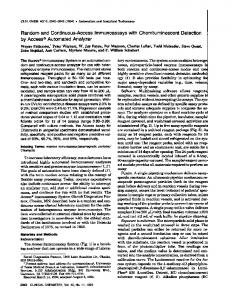
Fig. 2. An ArtiFlow workflow schema for the CAPA Workflow
Presellable, Sealed up by Court, or Frozen by REAB, etc as the application is reviewed. The CAPA workflow is triggered by the submission of an application for preselling by a developer. The REAB receives the application, justifies it according to relevant laws and regulations via a process consisting of automated services and human tasks, changes the status of listed apartments, and finally decided if the preselling application can be approved. An approved application will result in a corresponding Preselling Approval Certificate (PAC) from REAB. The developer can then proceed to sell those apartments listed in PAC. We now briefly outline the key elements in ArtiFlow and then show how the CAPA workflow can be modeled using ArtiFlow. ArtiFlow has four types of basic elements: “(business) artifacts”, “services”, “repositories”, and “events”. An artifact stores the essential information needed for completing a workflow execution including initial input data, temporary data needed during the process, the final results, and the information about the enactment at the current point (e.g., what has been done, context, etc.). An artifact-centric modeling approach starts from
6
G. Liu, X. Liu, H. Qin, J. Su, Z. Yan, and L. Zhang
identifying the artifacts [5]. In ArtiFlow, an artifact type is represented by a name with an associated XML Schema type. Unlike business data or objects, artifacts (types) in artifact-centric models should have their lifecycles specified. In fact, the lifecycles effectively provide a declarative functional specification of the workflow. The ArtiFlow model defines lifecycle specification as a graph, where nodes are either “services” or “repositories” and edges indicate how the artifacts move between services and repositories. A repository may store one or more types of artifacts (instances). In an ArtiFlow graph, a repository is shown as a circle with a unique name indicating the “state” of the processing for artifacts stored in it. In ArtiFlow, a service acts on one or more artifacts, e.g., it could create artifacts, or read the information in the input artifacts, could also access external information sources, and finally modify parts of the input artifacts. Services are shown as rectangles with rounded corners in ArtiFlow. Directed edges in an ArtiFlow graph are between services and repositories where: an edge label indicates the artifact(s) traveling along the direction, the solid end of an edge (either ►or ■) is attached to the actor of sending/fetching the artifact(s). Typically, a solid end is attached a service; when it is attached to a repository, it means that the repository will send it out (e.g., using a trigger). A dashed edge means read-only access of data (or artifacts). A service may be performed by a software system, a hardware device, or human. However, this distinction is not made in ArtiFlow. Instead, our model separates invocable (e.g., typical WSDL, REST) services from non-invocable or autonomous ones. This is because workflow management needs to control the execution: when and what invocable services have to run, and needed artifacts are ready in place for noninvocable services. ArtiFlow manages execution control through the use of “events”; in particular, each invocable service should have at least one associated event. An event in ArtiFlow represents a change either external to or internal in the workflow execution that needs the attention from the workflow manager. Examples of external events include submission of an application form. Internal events are primarily generated by the end of a service execution. An event may have an associated message which records the information of the event. Each event has a handler (shown as a concave pentagon); each internal event also has a producer (shown as a convex pentagon). A handler inside a service indicates that the service should be invoked if the event happens. The bottom of Figure 2 shows the elements and their graphical representation in ArtiFlow. We now present the ArtiFlow model of the CAPA workflow described above. Fig. 2 shows the detailed CAPA workflow that interacts with other workflows in REAB. Two key artifacts identified are • Preselling Approval File (PAF) that maintains necessary information for reviewing and approval. Specifically, it contains the original App-Form received from the developer and (space for) E-Docs. However, only the App-Form will be modified through the workflow, others are just for reference. A PAF artifact is created upon receiving a Presell Approval application from a developer. • Building List (BL) that contains all data about apartments proposed to be sold in the preselling request, such as building number, floor number, purpose, and status.
Automated Realization of Business Workflow Specification
7
The physical properties (e.g., floor number) in a BL remain fixed whereas the purpose and status fields are clarified, checked, and approved as the CAPA reviewing process progresses. Fig. 2 illustrates the CAPA workflow as an ArtiFlow graph and the (names of) three preceding workflows mentioned above. In the AritFlow model, the submission of a Commercial Apartments Preselling Application is modeled as an event E1 whose message contents contain the application form filled out by the developer. The CAPA workflow starts upon this event. Specifically, the handler of the event E1 invokes the service Receiving App-Form, Preparing File. The service creates a new artifact instance of PAF, fetches the necessary documents E-Docs, packages the E-Docs information into the artifact, and finally stores the new artifact in the repository CAP App-Form Received. In general, each artifact during the execution of an ArtiFlow workflow is temporarily stored in a repository. A Preliminary Decision (through the service with the name) is then made and followed by a Secondary Review, both of which need the corresponding artifact BL. Note that these two tasks are not invocable, i.e., they are always running and act on an artifact when it becomes ready. When Secondary Review completes successfully, a payment notification is sent to the applicant. Upon receiving the payment (event E2), the payment is recorded into the artifact, the services Preparing Certificate and Final Approval complete the CAPA workflow, and as a side effect, a certificate is made and the PAF artifact is modified to note this fact. Finally, the certificate is sent to the applicant, and the final PAF artifact is deposited into a shared Real Estate Database so that other workflows can access. Note that the corresponding artifact BL has a different path whose contents are written by the Final Approval process before it is stored back into the share database.
3
Translation of ArtiFlow to WS-BPEL: An Initial Approach
Our goal is to translate automatically an ArtiFlow workflow into an executable workflow. There are many choices for the target executable workflow language. As a starting point, we consider BPEL as the target language. In this section, we outline the key elements for the translation and illustrate it with the CAPA workflow example. We shall discuss several technical issues in Section 4. In the translation, we focus on four primitive constructs of ArtiFlow: services, events, artifacts and repositories. In the translation, we only consider invocable services, since the autonomous ones need no control of their executions. For them, the workflow engine only needs to deposit the artifacts in their input repositories. To simplify the following discussion, we assume a fixed ArtiFlow workflow. Clearly, BPEL does not provide artifacts/repositories. We construct a data (controller) service that handles all artifact-related operations in ArtiFlow, i.e., retrieving, storing an artifact. The service manages a database that stores the contents of all artifact repositories. The data service performs simple tasks: it receives a request and translates it into and executes an SQL command that perform data-related operation in the specified repository.
8
G. Liu, X. Liu, H. Qin, J. Su, Z. Yan, and L. Zhang
Fig. 3. Translated BPEL process (flow controller) of the CAPA workflow
The ArtiFlow workflow graph under question is realized by a BPEL process that we call a flow controller. The flow controller handles all ArtiFlow events and invocation of services including the data service. Services in ArtiFlow are simply mapped to partner links of the flow controller. Events in ArtiFlow control the execution flow and they simply become BPEL events for the flow controller. The event handlers in the flow controller listen to artifact requests and event messages, when an event with a message arrives, the flow controller simply forward it to the corresponding service (or artifact repository) by invoking the service. If the service requests an artifact, it invokes the flow controller, which then invokes the data service. After the data service is completed, the result is converted to a message and sent to the service. The mapping from ArtiFlow primitives to BPEL sample code fragments is shown in Table 1. The translation from ArtiFlow to BPEL is done with the following three steps. 1. Build partner links and interface according to the invocable services in the ArtiFlow workflow. (We assume WSDL services here.) Specifically, for each invocable service, a partner link and a partner link type are constructed. Port types of the services are copied to the associated WSDL of the translated BPEL process, and each port type is mapped to one role in the partner link type definition.
Automated Realization of Business Workflow Specification
9
Table 1. Mapping of ArtiFlow primitives to BPEL ArtiFlow primitive
BPEL sample
Service
WSDL: BPEL:
Event for service enactment
… …
Artifact request and issue
… Artifact repository
Repository
Database operated by Data Controller Service
2. Construct databases for repositories and the data controller service. We use a database for each repository and build the data controller service to perform all necessary data operations in ArtiFlow. We then add the partner link and partner link type for the data controller service. 3. Add the event handlers to the (BPEL) flow controller. The event handlers route each event and message to the corresponding service or repository. If the event enacts a service in BPEL, the service is invoked by forwarding the event message. If the message is a request for an artifact, the event handler sends the request and conditions to the data controller, after the data controller finishes the operation, it replies the service by forwarding the data controller’s reply. Some more actions may be added to the on event branches according to the policies of the ArtiFlow process (such as the actions when no satisfied artifacts can be found). Using the above steps, we can translate the CAPA ArtiFlow graph into BPEL automatically. Fig. 3 shows a part of the translated BPEL process (flow controller) for the CAPA workflow. The Client partner link is the interface of the BPEL process itself, and each service maps to one partner link, each artifact repository maps to one database. All event and message routing are processed in the onEvent branch of event handlers in the BPEL process. “Receive system start” and “Receive system
10
G. Liu, X. Liu, H. Qin, J. Su, Z. Yan, and L. Zhang
end” in a sequence are the only activities in the main process of BPEL which is used for system initiation and system termination. The main process is used to keep the process listening to the coming event and messages until the process terminates. The translated BPEL process can then be deployed on a BPEL engine.
4
Technical Issues and Challenges
The translation described in Section 3 is mostly straightforward as it addresses the core issue of realization without considering many factors in the operating environment, e.g., optimizations, and constraints. In this section, we briefly discuss a range of such issues that a practical operational workflow system must address. 4.1
Management of logical and physical enactments
In this subsection we first describe the enactment of the BPEL process translated using the method described above, analyze its advantages and disadvantages, then give an alternative translation strategy and have a comparison between the two strategies. In Section 3, we outlined a translation of ArtiFlow workflows into BPEL: using a global event handler to deal every arrival event, regardless its target process, so-called global event handler strategy. Using this strategy, the ArtiFlow is realized as a controller over a collection of independent services. The order of the events arrival is unnecessary specified. Thus we can keep the most flexibility of the flow. A glance over the physical enactment of the translated CAPA workflow is given as following. Once the global event handler receives the message Client:E1 upon event E1, the service, Receiving_App-Form_&_Preparing_File (RAFPF) is invoked. The arrival of message Store:PAF from RAFPF will cause invoking service DataController to store the newly created artifact. At the arrival of message Payment_Processing:E3, services Preparing_Certificate is invoked…till an execution of the BPEL flow controller completes. It is easy to find out that there is no explicit relationship between the invoked services, i.e., the same flow controller may invoke two services for two different workflow enactments. Each service is invoked in response of the corresponding message, and the state-change is kept in the related artifacts. The event handler is stateless. The approach is simple and fairly easy to implement with a centralized messaging handling that may be easy to tune for performance. On the other hand, it is hard to trace or monitor a particular enactment of an ArtiFlow workflow because there is a single BPEL flow controller instance for all workflow enactments, and it needs additional mechanism for correlations. An alternative translation strategy may be an enactment aware flow controller— each ArtiFlow enactment corresponds to its own BPEL flow controller instance. Under this approach each new enactment starts a new BPEL flow controller and there is a one-to-one correspondence between flow controller instances and enactments. Such an approach allows easy monitoring and auditing. A central issue is whether physical workflow enactments and logical enactments should correspond and the management of their relationships.
Automated Realization of Business Workflow Specification
11
The notions of pool and lane in BPMN reflect the physical properties (location, agents, etc.) of the services and workflow. The ArtiFlow model does not currently have the corresponding concepts. Clearly, a practical realization should allow the specification of physical properties of services that can be used by translation algorithms. 4.2
Feasible workflow realization
A workflow execution may be distributed geographically over many locations, each of which may manage its own resources including data. Also, the services in a workflow may also have their own access privileges on, especially data in an artifact. We enumerate some of the questions below. Data modeling and management. There are several issues concerning the design of the management mechanism for artifacts (and other documents) in a workflow. One issue is the data modeling for all the data involved, including artifacts. In the following discussion, we assume the use of relational DBMS in storing and access artifacts. On an extreme, one may view an artifact as a tuple and design a relation schema for each artifact class. This might be adequate if the artifact class does not have complex data and the normalization. However, the artifact PAF has a rather complex structure. In particular, it contains information from external sources (this part of information will be read only and not changed throughout the CAPA workflow). In this case, it may be more appropriate to view each PAF artifact as a single database and employ the usual design techniques. To manage multiple artifacts, we could simply attach an artifact id to all tuples in the databases for involved artifacts. There is, however, the need for views. One use of views is to model the part of a PAF artifact that store the external information. The technical question is the design of the view mechanism that involves external data (e.g., from relation databases). Another use of views is that different services should see different parts of the PAF artifact. Such views should be updateable since the changes on the views by a service should be reflected in the artifact. The second class of decisions concern how many database should we have. Clearly, one database per repository is sufficient but may not be optimal since we can always merge the databases into a single one and use tags to identify the repositories they are currently in. This, however, needs to take into consideration of the organizational boundaries and geographical locations (network speed). It would be desirable to develop a technical model for studying this problem. Distributed control flow management. In the ArtiFlow realization outlined in Section 3, the BPEL process is the global event handler: it receives an event/request and dispatches it to an appropriate partner. One would naturally ask if services are distributed over many geographical locations, is it necessary to have multiple event handlers? Or even if all services are geographically co-located, is there a need for more than one event handler from performance considerations? Although the event handler behaves like a receptionist, a global event handler simplifies the execution machinery, but on the other hand, it adds dependencies and thus the cost for maintenance. By reducing the number of services an event handler would interact, the impact of changes to the services would be constrained to only the local handler.
12
G. Liu, X. Liu, H. Qin, J. Su, Z. Yan, and L. Zhang
Operations on workflow execution. In the CAPA workflow, it is very desirable to time service executions (e.g., in order to fulfill SLA for the approval workflow). In this case, if an exceptional situation happens, a service should be permitted to “suspend” the execution. This allows the clock to be stopped and the current context and state of the artifact to be saved. The dual operation would “resume” the enactment. In the current realization, the context only refers to the executing service. It is an interesting question to make the context notion definable for specific workflows. For example, one would allow the context to also include the information about one or more of the following: the number of active Preselling Applications or PAF artifacts at the moment, the current time, the environment for the workflow, e.g., the number of unsold units in previously approved Preselling filings. These issues are worth further investigation. In addition to suspend/resume, there may be other operations on workflow executions. For example, one PAF application may be split into two after the preliminary approval is completed. Also, one may allow execution to proceed until some conditions are met, e.g., a specified time has been reached, or to terminate the workflow.
4.3
Workflow transactional properties
In all business processes, the notion of a transaction is vital. In ArtiFlow, a transaction mechanism has to guarantee to remain in “consistent” states for each workflow enactment. There are at least two categories of transactions, namely database transactions and workflow transactions, and their issues are different. For database transactions, one can use the transaction mechanism provided by an underlying DBMS. Database transactions ensure that what’s written into the database being managed makes (logical) sense, i.e., satisfies the ACID properties. This is a good first step. However, transactional properties in ArtiFlow workflows are different. For instance, artifacts in ArtiFlow are logical business objects; they could be composed of data stored in multiple databases, e.g., a PAF artifact in our running example. As a result, updating an artifact usually requires accessing multiple underlying databases that might be autonomously maintained by many stockholders. Relying only on the individual database transactions may not be sufficient. For example, if two database transactions commit and a third failed on one enactment (one or more artifacts), in what sense redo the failed database transaction is consistent with the workflow execution? Also, from the other angle, a correct workflow enactment may require some committed database transactions to be “compensated” or logically “rolled back”. It is unclear what the right notion of a “workflow transaction” should be, although it is apparent that it is not identical to a (local) database transaction. The workflow transaction issues in ArtiFlow may be related to several WS-* specifications, such as WS-Coordination, WS-Atomic Transaction, and WS-Business Activity developed by OASIS WS-TX TC. However, these proposals concern merely about how to “program” rather than what the logical notion is. The framework provided by the Phoenix project [1] may be a starting point to explore.
Automated Realization of Business Workflow Specification
4.4
13
Safety of workflow executions
The final group of issues concerning realization is on the safety of execution. An ArtiFlow workflow is safe if every execution completes within finite steps. The safety notion is independent of whether the business logic is correctly formulated in the workflow. There are many possibilities that an execution may not complete. For example, if two services executing on different enactments are competing for resources (e.g., artifacts) they may get into a deadlock. Also, if the fetch conditions on artifacts are not properly formulated, some artifacts may forever stay in a repository. Other situations may include live lock, non-terminating executions, etc. It is clear that many of these properties have been well studied. Static analysis or dynamic checking techniques should be included in practical ArtiFlow realization algorithms.
5
Conclusions
In this paper we outline an approach to automatically translate business workflow specification to executable workflows. The possibility of translation is largely due to the use of a data-centric workflow model which describes detailed workflow semantics through data. This translation establishes a nice correspondence between the executable workflow and components and the specification. The use of an artifactcentric model in the translation and the fact artifact-centric models are gaining acceptance in the BPM arena brings a huge potential: workflow management at business level, easy performance (KPIs) management and monitoring, support for interoperation, etc. However, there are many technical obstacles to overcome.
Acknowledgments. The authors are grateful to participants in group discussions that lead to this paper, including Leilei Chen, Weihua Chen, Qi He, Ying Wang, and Yong Yang.
References 1. R. Barga and D. B. Lomet. “Phoenix: making applications robust.” In Proc ACM SIGMOD Int. Conf. on Management of Data, 1999, pages.562-564 2. K. Bhattacharya, N. S. Caswell, S. Kumaran, A. Nigam, and F. Y. Wu. “Artifact-centered operational modeling: Lessons from customer engagements.” IBM Systems Journal, 46(4):703-721, 2007 3. K. Bhattacharya, C. Gerede, R. Hull, R. Liu, and J. Su. “Towards formal analysis of artifact-centric business process models.” In Proc. Int. Conf. on BPM, 2007, pages 288-304 4. K. Bhattacharya, R. Guttman, K. Lyman, F. F. Heath III, S. Kumaran, P. Nandi, F. Wu, P. Athma, C. Freiberg, L. Johannsen, and A. Staudt. “A model-driven approach to industrializing discovery processes in pharmaceutical research.” IBM Systems Journal, 44(1):145-162, 2005
14
G. Liu, X. Liu, H. Qin, J. Su, Z. Yan, and L. Zhang
5. K. Bhattacharya, R. Hull, and J. Su. “A data-centric design methodology for business processes.” In Handbook of Research on Business Process Modeling, 2009 6. T. Chao, D. Cohn, A. Flatgard, S. Hahn, M. Linehan, P. Nandi, A. Nigam, F. Pinel, J. Vergo, and F. Wu. “Artifact-based transformation of IBM global financing.” In Proc. Int. Conf. on BPM, 2009, pages 261-277 7. D. Cohn and R. Hull. “Business artifacts: A data-centric approach to modeling business operations and processes.” IEEE Data Engineering Bulletin, 32(3):3-9, 2009 8. R. Hull and J. Su. Report on 2009 NSF Workshop on Data Centric Workflows, 2009 9. A. Lapouchnian, Y. Yu, and J. Mylopoulos. “Requirements-driven design and configuration management of business processes.” In Proc. Int. Conf. on BPM, 2007, pages 246-261 10. A. Nigam and N. S. Caswell. “Business artifacts: An approach to operational specification.” IBM Systems Journal, 42(3):428-445, 2003 11. H.A. Reijers, S. Limam, and W.M.P. van der Aalst. “Product-based workflow design.” Journal of Management Information Systems, 20(1):229-262, 2003 12. W. M.P. van der Aalst. “Business process management demystified: A tutorial on models.” Systems and Standards for Workflow Management, Lectures on Concurrency and Petri Nets, 2004