CC-101 Screw Feeder. CC-103 Recycle conveyor. M1 Screw Feeder Motor. M8 Bucket Elevator Motor. M1. M2. M3. M4. M5. M6. M7. M8. S Speed Controller.
Multiagent realization of prediction-based diagnosis and loss prevention Roz´alia Lakner1 , Erzs´ebet N´emeth2,1 Katalin M. Hangos2 , and Ian T. Cameron3 1
2
Department of Computer Science, University of Veszpr´em, Veszpr´em, Hungary Systems and Control Laboratory, Computer and Automation Research Institute, Budapest, Hungary 3 School of Engineering, The University of Queensland, Brisbane, Australia 4072
Abstract. A multiagent diagnostic system implemented in a Prot´eg´eJADE-JESS environment interfaced with a dynamic simulator and database services is described in this paper. The proposed system architecture enables the use of a combination of diagnostic methods from heterogeneous knowledge sources. The process ontology and the process agents are designed based on the structure of the process system, while the diagnostic agents implement the applied diagnostic methods. A specific completeness coordinator agent is implemented to coordinate the diagnostic agents based on different methods. The system is demonstrated on a case study for diagnosis of faults in a granulation process based on HAZOP and FMEA analysis.
1
Introduction
For complex multiscale process systems that are difficult to model, a combination of model-based analytical and heuristic techniques is usually needed to develop a diagnostic system [1]. The approach of multiagent systems (MAS) [2] which emerged in AI represents a promising solution for such a diagnosis task, being based on information from heterogeneous knowledge sources [3]. A multiagent system can then be used for describing the system model, the observations, the diagnosis and loss prevention methods with each element being established through formal descriptions. This work investigates the use of the architecture and algorithms of multiagent systems for diagnosing faults in process plants when both dynamic models and heuristic operational knowledge of the plant are available. In particular, we consider a granulation process and the advice to operators in order to reduce potential losses. The significance of this work lies in a coherent fault detection and loss prevention framework based on a well-defined formalization of complex processes and the diagnostic procedures.
2 2.1
Main processes and techniques in fault detection and diagnosis Fault detection, diagnosis and loss prevention
Early detection and diagnosis of process faults while the plant is still operating in a controllable region can help avoid abnormal events and reduce productivity loss. Therefore diagnosis methods and diagnostic systems have practical significance and strong traditions in the engineering literature. The diagnosis of process systems is usually based on symptoms. Symptoms are deviations from a well-defined ”normal behaviour”, such as Tlow = (T < Tmin ) which is defined by using a measurable temperature variable T . In the case of a dynamic system the measurable quantities are time-varied, so the symptoms related to these variables will also change with time. In model-based fault detection and diagnosis one usually assigns a so-called root cause to every faulty mode of the system, the variation of which acts as a cause of the fault. In the case of a fault it is usually possible to take actions in the initial phase of the transient to avoid serious consequences or to try to drive the system back to its original ”normal” state. Dedicated input signal(s) serve this purpose for each separate fault (identified by its root cause) where the preventive action is a prescribed scenario for the manipulated input signal. 2.2
HAZOP and FMEA analysis
The information available for the fault detection and diagnosis task is typically derived from a variety of sources which have varying characteristics. These sources include conceptual design studies and risk analyses as well as detailed dynamic models for parts of the system or for specific operating modes [4]. Heuristic operational experience is often elicited from operators and other plant personnel. The heuristic information can be collected with systematic identification and the analysis of process hazards, as well as the assessment and mitigation of potential damages using so-called Process Hazard Analysis (PHA). There are several methods used in PHA studies such as Failure Modes and Effects Analysis (FMEA), Hazard and Operability Analysis (HAZOP), Fault Tree Analysis (FTA) and Event Tree Analysis (ETA). The Hazard and Operability study is the most widely used methodology for hazard identification. HAZOP [5] is a systematic procedure for determining the causes of process deviations from normal behaviour and the consequences of those deviations. This works on the fundamental principle that hazards and operational problems can arise due to deviations from normal behaviour. It addresses both the process equipment, operating procedures and control systems (in this case, known as CHAZOP). Failure mode and effect analysis (FMEA) [6] is a qualitative analysis method for hazard identification, universally applicable in a wide variety of industries. FMEA is a tabulation of each system component, noting the various modes by
which the equipment can fail, and the corresponding consequences (effects) of the failures. FMEA focuses on individual components and their failure modes. HAZOP and FMEA provide a comprehensive analysis of the key elements that help constitute an effective diagnostic system. The incorporation of failure modes can greatly enhance the tool’s capabilities. 2.3
Prediction-based diagnosis
Prediction of a system’s behaviour is used for deriving the consequences of a state of the system in time that is usually performed in process engineering by dynamic simulation. With the help of prediction, however, the faulty mode of the system can also be detected based on the comparison between the real plant data and the predicted values generated by a suitable dynamic model. This type of fault detection and diagnosis is called prediction-based diagnosis [7]. Because process systems are highly nonlinear and their models can be drastically altered depending on the actual fault mode, simple reduced models are needed for prediction-based diagnosis.
3
Knowledge representation of the diagnostic system
The proposed framework for a multiagent diagnostic system consists of an ontology design tool and a multiagent software system. The domain specific knowledge is represented as modular ontologies using the ontology design tool Prot´eg´e [8]. This knowledge is integrated into a multiagent software system where different types of agents cooperate with each other in order to diagnose a fault. 3.1
Process-specific ontology
The process-specific ontology describes the concepts, their semantical relationships and constraints related to the processes in question, similar to the general ontology for process systems given by OntoCAPE [9]. The process-specific ontology has two different parts, namely the common knowledge of the general behaviour of the process systems and the application-specific knowledge. This description defines the structure of a general process model for the process in question and enables the construction of a concrete process model realization which can be used as a dynamic simulation both in real-time simulation and in prediction-based diagnosis. 3.2
Diagnostic ontology
The knowledge from human expertise and operation about the behaviour of the system in the case of malfunction, together with the reasons, consequences and possible corrections is described here. The diagnostic ontology contains the semantic knowledge on diagnostic notions (e.g. symptoms, root causes), different kind of tools such as FMEA and HAZOP tables and procedures such as reasoning based on FMEA or HAZOP knowledge.
3.3
Real-time database
Both the process-specific ontology and the diagnostic ontology contain timevarying elements such as process variables, actuator variables and their related variables. The values of these variables can be supplied by either a real process or a simulator and can be stored in the real-time database.
4 4.1
The multiagent diagnostic system The main elements of the multiagent diagnostic system
Similar to the ontology classification described above, the agents of the diagnostic system belong to three main categories such as process-related, diagnosticrelated and real-time service related agents. The process agents Process agents assist the user and the other agents in modelling and simulation of the process in question. This can be performed under different, faulty and non-faulty circumstances. Some types of process agents and their main tasks are as follows: – Process output predictors (PPs) provide prediction by using dynamic simulation with or without preventive action(s). – The prediction accuracy coordinator (PAC) checks the accuracy of the prediction result and calls additional agents to refine the result if necessary. – Model parameter estimators can be associated with each of the PPs. The PAC may call this agent by requesting a refinement of the model parameters when the accuracy of the agent is unsatisfactory. The diagnostic agents Diagnostic agents perform measurements, symptom detection, fault detection [7], fault isolation and advice generation for avoiding unwanted consequences. These agents may perform logical reasoning and/or numerical computations. Some types of diagnostic agents and their main tasks are as follows: – The symptom generator and status evaluator is based on non-permissible deviations that checks whether a symptom is present or not. – The state and diagnostic parameter estimators (SPEs) are advanced symptom generators that use several related signals and a dynamic state space model of a part of the process system to generate a symptom. – Fault detectors (FDs) use the services provided by SPEs or PPs to detect the fault(s) by using advanced signal processing methods. – Fault isolators (FIs) work in the case of the occurrence of a symptom to isolate the fault based on different techniques (fault-tree, HAZOP, FMEA, fault-sensitive observers etc.). – Loss preventors (LPs) suggest preventive action(s) based on different techniques that have been used for the HAZID and remedial actions (HAZOP, prediction, etc.).
– The completeness coordinator checks completeness of the result (detection, isolation or loss prevention) and calls additional agents if necessary. – The contradiction or conflict resolver (CRES) calls additional agents in case of contradiction to resolve it. The real-time agents Beside the two main categories, the diagnostic system contains the following real-time agents for controlling and monitoring the process environment: – Monitoring agents access and/or provide data from real world or from simulation. – Pre-processor agents detect the non-permissible deviations which can be the possible symptoms. – Control agents control the process in case of preventive actions. – Corroborating agents act on requests from diagnostic agents and provide additional measured values or information. 4.2
The structure of the multiagent diagnostic system
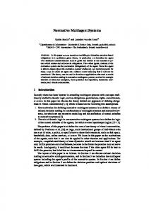
Several agent construction and simulation tools have been proposed in the literature by a number of researchers and commercial organizations. A non-exhaustive list includes: ABLE [10], AgentBuilder [11], FIPA-OS [12], JADE [13] and ZEUS [14]. The JADE (Java Agent DEvelopment Framework) has been chosen as the multiagent implementation tool, that has integration facilities with the Prot´eg´e ontology editor and the Java Expert System Shell (JESS) [15]. The JADE agent platform can be split into several containers which are separate JAVA virtual machines and contain agents implemented as JAVA threads. The communication among the agents is performed through message passing represented in FIPA Agent Communication Language (FIPA ACL). JADE does not support inferencing techniques but it can be integrated with some reasoning systems, such JESS and Prolog. JESS is a rule engine and scripting environment written in the JAVA language. It possesses both a very efficient forward chaining mechanism using the Rete algorithm as well as a backward chaining mechanism. The dynamic models for the simulations are implemented in MATLAB. MATLAB serves to generate real-time data of the simulated process system and it contains the simplified models for prediction. The communication between MATLAB and JADE is solved by the TCP/IP protocol. For storing the huge amount of archive data a MySQL database is used. The connection between JADE and MySQL databases is realized by MySQL Connector/J. The main elements and the software structure of the proposed multiagent diagnostic system implemented in JADE can be seen in Figure 1.
5
Case study
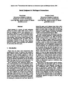
The proposed methods and the prototype diagnostic system are demonstrated on a commercial fertilizer granulation system [16]. The simplified flowsheet of
Real process or real-time simulator
Monitoring Agent
Real-time database
Corroborating Agent
PreProcessor Agent
Control Agent
Real-time agents Based on Real-time database ontology ACL messages Agent Directory Management Facilitator System RMI server (for communication)
Remote Monitoring Agent (GUI)
Diagnostic agents Based on Diagnostic ontology (HAZOP, FMEA)
Model parameter estm i ator
Predcio ti n accuracy coordn i ator
Processoutput predcitor
Contradcio ti nor concifltresovler
ACL messages
Compe l teness coordn i ator
Stateanddiagnostci parameterestma i tor
Losspreventor
Fautslioa l tor
Fautldetector
Symptom generator
ACL messages
Process agents Based on Process-specific ontology
Fig. 1. The structure of the multiagent diagnostic system
the plant with the variables used by the diagnostic system is shown in Fig. 2. The aim of the case study was to investigate the cooperation of the diagnostic agents, therefore we have selected a case when the diagnostic result can only be obtained by a combination of different fault detection and isolation methods.
5.1
Knowledge elements of the granulation diagnostic system
There are two different types of knowledge elements in the granulator diagnostic system. The dynamic process models that contain traditional engineering knowledge of a process plant in the form of a set of differential-algebraic equations and the systematically collected heuristic knowledge that originates from a HAZOP or FMEA analysis. The results of the HAZOP analysis are collected in a HAZOP result table, the structure of which is shown in Fig. 3. It defines logical (static) cause-consequence relationships between symptoms and potential causes that can be traced to root causes of the deviation. The table in Fig. 3 illustrates two related symptoms with at least two different causes each. A possible cause is regarded as a root cause if it refers to a failure mode of a physical component in the system, for example cause (2) in the second row of the HAZOP table. When such a root case is found we can complement or refine the diagnosis result by using the corresponding item from the FMEA table also shown in Fig. 3.
HP-101 Feed Hopper CC-101 Screw Feeder CC-103 Recycle conveyor M1 Screw Feeder Motor M8 Bucket Elevator Motor
T-101 Binder tank P-101 Binder pump PRV-101 Pressure relief
Binder (S3)
T-101
VC-101 Video Camera HE-101 Dryer Bar Heater RD-102 Rotary Dryer VS-101 Vibratory Sieve M3 Rotary Drier Motor M5 Vibratory Sieve Motor V1 Vibrator for shute
RD-101 Granulator CR-101 Roll Crusher CC-102 Belt Weigher/Conveyor M2 Rotary Drum Motor M6 Crusher Motor M7 Belt Weigher Motor V2 Vibrator for recycle shute
HE-102 Air Heater FN-101 Fan M4 Fan Motor
PRV-101 F FT 103
FE 103
FT 102
FE 102
UNAC/PLC Control System
F
P-101
Fresh Feed (S1) S1
FC 103
F FT 101
FC 102
FE 101
HP-101
from ST101 W101
FC 101
S3b
S3a
V 101
S3c
S1
TT 102
HE-101
RD-101
TE 101
V2
S4 M2 S-10
SC 102
M8 SC 107
CC-103
JC 101
M4
3 Phase
RD-102
air From PLC/UNAC
air
V1
SC 101
From PLC/UNAC
S2 M1
SC 104
VC-101
CC-101
Air (S5)
S5 HE-102
S6
M3
FN-101
Trip SC 103
S 105
S7
HT 101
manual
Oversize
S10
FT 104
VS-101
Product (S11)
S11
CR-101
M6
S8
M5
S9 JC 102
Undersize CC-102 Control Legend S Speed Controller T Temperature Controller W Weight Controller ST Tachometer F Flow controller VC Video Camera V Vision system J Power Controller H Humidity Measurement CS Control System P Pressure
ST 101 To PLC/UNAC
M7 S 106
Granulation Pilot Plant From PLC/UNAC
Department of Chemical Engineering The University of Queensland W 101
Date: 17 / 02 / 04 Drawn:
C. Atkinson / I.Cameron
SIZE
FSCM NO
A4 SCALE
DWG NO
REV
GP-1001 NTS
SHEET
3 1 OF 1
Fig. 2. Granulation pilot plant schematic
5.2
Simulation results
In order to illustrate the operation of the proposed agent-based diagnostic system, only a part of the system, namely the diagnostic agent-set, based on logical reasoning is demonstrated. The structure of the agent-system can be seen in the left-hand side of Figure 4. Apart from the built-in main-container’s agents, the agent platform contains three containers: the first for the real-time agents (MonitoringAgent and PreProcessorAgent), the second for the diagnostic agents (SymptomGeneratorAgent, FaultIsolatorAgents - based on both HAZOP and FMEA analysis, CompletenessCoordinatorAgent and LossPreventorAgent) and the third for a process agent (ProcessOutputPredictor). The main behaviour of the diagnostic agents is the logical reasoning based on heuristic knowledge (HAZOP, FMEA) with the help of the JESS rule engine. The communication and the operation of the diagnostic agent sub-system can be seen in the right-hand side of Figure 4. Based on the variable-values supplied by the MonitoringAgent the PreProcessorAgent determines the deviances in the system. In the case of deviance the SymptomGeneratorAgent checks the presence of symptoms and informs the CompletenessCoordinatorAgent. It calls the FaultIsolator- and LossPreventorAgent to determine the possible faults and suggest preventive actions. In case of multiple faults the FMEAFaultIsolatorAgent refines the result. Based on the suggestions of these agents the CompletenessCoordinatorAgent orders the oper-
Guideword Mean Particle Diameter (D50)
Slurry feed flow
Deviation LESS
LESS
Possible causes
Consequences
(1) Decrease in fresh feed size
(2) Decrease/loss of slurry flow (1) operator error in setting the flowrate (2) failure in valve actuator (3) failure in valve causing closure (4) reduced slurry production in preneutralizer
Action required
* decrease in system holdup
a) increase fresh feed size
* change in granulation condition * change in recycle PSD
b) change to original feed type c) increase slurry flow
* reduced liquid phase in granulator * lack of granulation * lower product size range flow from granulator
The structure of a HAZOP result table ComDescripponent tion FCV Slurry flow control valve
Failure mode Stuck
Possible causes maintance failure
Effects Local loss of flow control
Detection System potential product indirectly via quality impacts product quality
corrosion Closed
lower or no flow
Criticality
Action
MEDIUM - review maintenance quality procedures reduction in product
no growth D50 reduces in product
Open
The relevant part of the FMEA table Fig. 3. HAZOP and FMEA result tables
ation of the ProcessOutputPredictor for predicting the behaviour of the system with the preventive action. The diagnostic process performed by the above agents is illustrated on the example of a symptom, when the mean particle diameter (d50 ) is less than a limit value. This situation corresponds to the rows of the HAZOP table seen in Fig. 3. A part of these diagnostic agents’ conclusions can be seen in Fig. 5 where the messages about the operation of the HAZOPFaultIsolatorAgent are listed. The above listed diagnosis and loss prevention results has been refined the diagnostic results based on the FMEA analysis initiated by the CompletenessCoordinatorAgent and the unique root cause "Slurry flow control valve fails Closed" has been deduced.
6
Conclusion and discussion
A novel coherent fault detection and loss prevention framework for process systems is proposed in this paper implemented in a Prot´eg´e-JADE-JESS environment that has clearly shown the advantages of such a technology in building
Fig. 4. The structure and the communication of the agent system
Fig. 5. The HAZOPFaultIsolatorAgent’s conclusion
complex diagnostic systems based on heterogeneous knowledge sources. The process ontology and the process agents based thereon have been designed following the structure of process systems that is first explored in [17] where a Coloured Petri Net-based diagnosis system is described. The diagnostic procedures based
on model-based reasoning have been developed for a G2-based intelligent diagnostic system in [18] where the need for combining the different fault isolation methods to refine the diagnosis has arisen.
Acknowledgements This research has been supported by the Hungarian Research Fund through grants T042710 and T047198, which is gratefully acknowledged, as well as the Australian Research Council International Linkage Award LX0348222.
References 1. Blanke, M., Kinnaert, M., Junze, J., Staroswiecki, M., Schroder, J., Lunze, J., Eds, Diagnosis and Fault-Tolerant Control. Springer-Verlag. (2003) 2. Jennings, N., R.,Wooldridge, M., J.: Agent Technology, Springer-Verlag, Berlin. (1998) 3. W¨ orn, H., et al.: DIAMOND: Distributed Multi-agent Architecture for Monitoring and Diagnosis, Production Planning and Control. 15 (2004) 189–200 4. Cameron, I.T., Raman, R.: Process Systems Risk Management. Elsevier, (2005) 5. Knowlton, R., E.: Hazard and operability studies : the guide word approach, Vancouver: Chematics International Company (1989) 6. Jordan, W.: Failure modes, effects and criticality analyses. In: Proceedings of the Annual Reliability and Maintainability Symposium, IEEE Press (1972) 30–37 7. Venkatasubramanian, V., Rengaswamy, R., Kavuri, S., N.: A review of process fault detection and diagnosis Part II: Qualitative models and search strategies. Computers and Chemical Engineering 27 (2003) 313–326 8. The Prot´eg´e Ontology Editor and Knowledge Acquisition System, (2004) http://protege.stanford.edu 9. Yang, A., Marquardt, W., Stalker, I., Fraga, E., Serra, M., Pinol, D.: Principles and informal specification of OntoCAPE, Technical report, COGents project, WP2. (2003) 10. Agent Building and Learning Environment (ABLE). http://www.research.ibm.com/able 11. Reticular Systems. AgentBuilder - An integrated Toolkit for Constructing Intelligence Software Agents. (1999) http://www.agentbuilder.com. 12. FIPA-OS. http://www.nortelnetworks.com/products/announcements/fipa/index.html. 13. JADE - Java Agent DEvelopment Framework. http://jade.tilab.com. 14. Nwana, H., S., Ndumu D., T., Lee L., C.: ZEUS: An advanced Tool-Kit for Engineering Distributed Multi-Agent Systems. In: Proc of PAAM98, (1998) 377–391 15. JESS, the Rule Engine for the Java platform. http://herzberg.ca.sandia.gov/jess/ 16. Balliu, N.: An object-oriented approach to the modelling and dynamics of granulation circuits, PhD Thesis, School of Engineering, The University of Queensland, Australia 4072. (2004) 17. N´emeth, E., Cameron, I. T., Hangos, K. M.: Diagnostic goal driven modelling and simulation of multiscale process systems. Computers and Chemical Engineering 29 (2005) 783-796. 18. N´emeth, E., Lakner R., Hangos K. M., Cameron I. T.: Prediction-based diagnosis and loss prevention using model-based reasoning. In: Lecture Notes in Artificial Intelligence, Vol. 3533, Springer-Verlag, (2005) 367-369.