ORIGINAL RESEARCH
Automated Spine Survey Iterative Scan Technique1
Institutional review board approval, with waived consent, was obtained to develop a spine-labeling algorithm with retrospectively obtained deidentified HIPAA-compliant data. An automated magnetic resonance (MR) imaging technique to rapidly survey the entire spine and provide definitive numbering of disks and vertebrae was compared with neuroradiologist assignments in 50 cases. Contiguous two-station sagittal fast gradient-recalled-echo sequences with 35-cm fields of view (FOVs) were preprogrammed for full cervical, thoracic, and lumbar spine coverage (combined 70-cm FOV, seven sections, 15 mm left of to 15 mm right of midline, 4-mm section thickness, 1-mm intersection gap, 512 ⫻ 352 matrix, 58/2.0 [repetition time msec/ echo time msec], 30° flip angle, 15.6-kHz bandwidth, 42second acquisition time). In all cases, the neuroradiologist could visualize and definitively number all cervical, thoracic, and lumbar levels on automated spine survey iterative scan technique localizer studies. Automated disk-vertebra detection and numbering were concordant with neuroradiologist assignments in all cases. The entire spine can be surveyed with subminute, submillimeter in-plane resolution MR imaging. Cervical, thoracic, and lumbar vertebrae and disks can be readily identified and definitively numbered by means of visual inspection or semiautomated computer algorithm. 娀 RSNA, 2006
1
From the Center for Imaging Research (K.L.W., J.M.S., R.B.B.), Department of Radiology, Section of Neuroradiology (K.L.W.), Department of Biomedical Engineering (K.L.W., J.M.S., R.B.B.), and Department of Psychiatry (K.L.W.), University of Cincinnati College of Medicine, PO Box 670762, 234 Goodman St, ML 0762, Cincinnati, OH 45267-0762; and the Neuroscience Institute, University Hospital, Cincinnati, Ohio (K.L.W.). Received March 16, 2005; revision requested May 6; revision received June 2; accepted June 22; final version accepted August 12. Address correspondence to K.L.W. (e-mail: kenneth
[email protected]). 姝 RSNA, 2006
Radiology: Volume 239: Number 1—April 2006
255
䡲 TECHNICAL DEVELOPMENTS
Kenneth L. Weiss, MD Judd M. Storrs, BS Richard B. Banto
TECHNICAL DEVELOPMENTS: Automated Spine Survey Iterative Scan Technique
L
imited coverage, spatial resolution, and contrast of conventional magnetic resonance (MR) imaging localizer studies coupled with the high prevalence of spinal variance make definitive numbering of vertebral disks and bodies difficult and may contribute to the risk of performing spinal intervention at the wrong level (1). Only 20% of the population exhibits the classic groupings of seven cervical, 12 thoracic, five lumbar, five sacral, and four coccygeal vertebrae. In 2%–11% of individuals, there is a cephalad or caudad shift of lumbar-sacral transition, which respectively results in 23 or 25 rather than the typical 24 mobile presacral vertebrae (ie, those cephalic to the first sacral vertebra) (2). Numbering difficulties are often heightened in patients referred for spine MR imaging. Such patients are more likely than the general population to have anomalies, acquired pathologic conditions, or prior spinal surgeries that distort the appearance of vertebrae and disks. Moreover, these patients are often unable to lie still within the magnet bore for more than a short period of time because of a high prevalence of back pain and spasms. Resultant intraimaging motion confounds image interpretation, and interimaging motion renders imaging coordinates and positional references unreliable. While data remain somewhat limited, authors report an approximately 2%–5% incidence of wrong level approach in spinal intervention, with most cases involving the lower lumbar interspaces (ie, intervertebral spaces) (3). Although several research techniques have been described to automate spine image analysis, to our best knowl-
Advances in Knowledge 䡲 The entire spine can be effectively surveyed with submillimeter inplane resolution MR imaging in less than 1 minute. 䡲 All cervical, thoracic, and lumbar vertebrae and disks can be readily numbered by means of visual inspection or the ASSIST semiautomated computer algorithm. 256
edge none has successfully addressed the need for accurate and unambiguous numbering (4–7). Computer characterization of a vertebra or disk is of limited clinical value if that structure cannot be accurately identified and named. Thus, the purpose of our study was to develop and test a spine-labeling algorithm by using retrospectively obtained data.
Materials and Methods Patients Institutional review board approval with waived consent was obtained for this Health Insurance Portability and Accountability Act– compliant research study. As part of a revised thoracic spine clinical MR imaging protocol instituted in January 2004 at an outpatient imaging facility, patients underwent MR imaging with a rapid automated spine survey iterative scan technique (ASSIST) with preset parameters with use of Food and Drug Administration–approved sequences to obtain localizer studies. A total of 50 such localizer studies were evaluated in two separate batches: The first batch of 27 studies was evaluated between March 10, 2004, and November 6, 2004, and the second batch (the remaining 23 consecutive studies) was evaluated between December 7, 2004, and February 7, 2005. Lack of ASSIST surface coil correction was the only reason for exclusion in the first batch. No studies were excluded in the second batch, as by then all studies were automatically surface coil corrected. Our study included 18 male and 32 female patients, with a mean age of 55 years and an age range of 17– 82 years. Imaging and Interpretation All studies were obtained with a 1.5-T MR imaging system (Excite; GE Medical Systems, Milwaukee, Wis) with a standard four-channel, six-element quadrature spine coil and surface coil correction algorithm. Contiguous two-station sagittal fast gradient-recalled-echo sequences with 35-cm fields of view (FOVs) were preprogrammed, providing full cervical, thoracic, and lumbar
Weiss et al
spine coverage. The combined sagittal FOV was 70 cm, seven sections were obtained at each station, and parameters were as follows: 15 mm left of midline to 15 mm right of midline, 4-mm section thickness with 1-mm intersection gap, 512 ⫻ 352 matrix, one signal acquired, 58/2.0 (repetition time msec/ echo time msec), 30° flip angle, 15.6kHz bandwidth, and an acquisition time of 21 seconds per station (ie, a total acquisition time of 42 seconds). To facilitate and standardize autoprescriptions, a line was drawn on the spine coil for the technologists to landmark (set as MR imager’s 0 coordinate) rather than have them use a superficial anatomic feature. The coil has a contoured headneck rest, which ensured grossly similar positioning of the craniocervical junction of each patient relative to this landmark. These ASSIST studies were deidentified in batches and were copied to compact disks for subsequent off-line review, computer algorithm development, and testing. A semiautomated disk detection and numbering algorithm was iteratively developed (J.M.S., K.L.W., R.B.B.), and results were compared with neuroradiologist (K.L.W.) assignments. The first 27 surface coil– corrected total spine localizer studies provided were initially assessed with an algorithm developed by using previously ob-
Published online before print 10.1148/radiol.2383050456 Radiology 2006; 239:255–262 Abbreviations: ASSIST ⫽ automated spine survey iterative scan technique FOV ⫽ field of view Author contributions: Guarantor of integrity of entire study, K.L.W.; study concepts/study design or data acquisition or data analysis/ interpretation, K.L.W., J.M.S., R.B.B.; manuscript drafting or manuscript revision for important intellectual content, K.L.W., J.M.S., R.B.B.; approval of final version of submitted manuscript, K.L.W., J.M.S., R.B.B.; literature research, K.L.W.; clinical studies, K.L.W.; experimental studies, K.L.W., J.M.S., R.B.B.; statistical analysis, K.L.W.; and manuscript editing, K.L.W., J.M.S., R.B.B. Authors stated no financial relationship to disclose. Radiology: Volume 239: Number 1—April 2006
TECHNICAL DEVELOPMENTS: Automated Spine Survey Iterative Scan Technique
Weiss et al
Figure 1
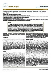
Figure 1:
(a) Abbreviated schematic diagram of the computer algorithm and (b) remaining iterations, as detailed in the Appendix.
tained ASSIST images that were not surface coil– corrected. This algorithm required manual input of two seed points (centroid of first and last interspaces) to achieve greater than 95% accuracy. The algorithm was subsequently modified by using these 27 surface coil– corrected studies as a new training set and as a database to provide normative values for algorithm modification. The modified algorithm, presented in the next section, requires manual input of only a single seed point (C2-3) and was retested on these 27 studies plus 23 subsequent studies. The latter were obtained from consecutive clinical thoracic MR examinations performed between December 7, 2004, and February 7, 2005, as detailed previously. An undergraduate engineering stuRadiology: Volume 239: Number 1—April 2006
dent (R.B.B.) with no previous radiology experience entered all computer algorithm seed points. The neuroradiologist (K.L.W.) was American Board of Radiology–Certificate of Added Qualification certified and had 19 years of experience with spine MR image interpretation. For all 50 studies, the neuroradiologist independently reviewed the seven composite (14 individual) ASSIST sagittal sections on a personal computer workstation configured with an Intel (San Jose, Calif) 2.8-GHz Xeon processor. In addition to numbering all disks and vertebrae, findings on studies that suggested prior surgery, congenital block vertebrae, or an atypical number of mobile presacral vertebrae were noted. Starting with the axis (vertebra C2), the visualized cervical, thoracic, and lumbar vertebrae were consecu-
tively numbered C2 through C7, T1 through T12, and L1 through L5.
Computer Algorithm As shown in the schematic diagram in Figure 1, the automated disk detection and numbering algorithm is a multistep iterative process. Digital imaging and communications in medicine ASSIST images of the cervicothoracic (top half) and thoracolumbar (bottom half) spine are first input into Matlab 7 (MathWorks, Natick, Mass) for digital image processing. Initially, these two data sets are processed separately by using different threshold values and disk constraint parameters (Figs 1a, 2). Image volumes are enhanced with a tophat filter, and background noise is suppressed (8). The posterior edge of the back is then 257
TECHNICAL DEVELOPMENTS: Automated Spine Survey Iterative Scan Technique
identified and search regions (green) are assigned (Fig 2). The program assigns the threshold values and applies a median spatial filter to the search re-
gions. Voxels exceeding threshold values (in orange) are then subjected to additional constraints (Fig 2). Acceptable voxels must extend onto
Figure 2
Figure 3
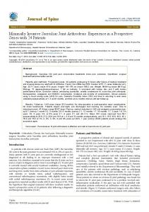
Figure 2: Seven-section sagittal MR imaging projectedvolumes;the35-cmFOVtopandbottomimage halvesofthespineillustratetypicalsearchregions(in green).Voxelsthatexceedthesignalintensitythreshold aredepictedinorange.Thosethatmeetadditionaldisk constraintsaredepictedinwhite.Yellowlinesconnect thecentroidsoftheseputativedisks(white)inthetop andbottomhalves.
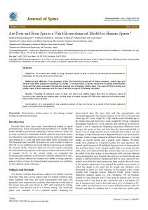
Figure 3: Combined sagittal MR image depicts search paths parallel to the (yellow) line connecting the centroid of C2-3 with the longest disk chains from the top and bottom half images from Figure 2. Dots correspond to filtered local maxima along these paths.
258
Weiss et al
at least two adjacent sagittal sections but not touch the boundary of the search region. They must lie 6 – 80 mm in the cervicothoracic and 8 –100 mm in the thoracolumbar region from adjacent candidate voxels. The centroids of these voxel clusters (candidate disks) are then connected. The angle subtended by the line connecting the centroid of adjacent candidate disks and the major axis of these disks must be between 45° and 135° in both the cervicothoracic spine and the thoracolumbar spine. Furthermore, for a disk (k) to be considered part of a disk chain, its closest superior neighbor must have k as its closest inferior neighbor, and k’s closest inferior neighbor must have k as its closest superior neighbor. The algorithm selects the longest disk chain (white disks connected by a yellow line) in the cervicothoracic and thoracolumbar regions, respectively (Fig 2). The technologist is instructed to approximate (ie, click on) the centroid of C2-3 at any time during or before the aforementioned candidate disk evaluation. The centroid of C2-3 and the longest disk chains in the cervicothoracic spine and thoracolumbar spine are connected with a straight line. By using three-dimensional linear interpolation, the program searches along this (yellow) line and along twelve adjacent parallel lines, although only four of the latter are discernable (different colors) in Figure 3 because of their superimposition in the sagittal projection. After applying Gaussian filters, the algorithm finds local intensity maxima along each path (red dots in Fig 3). Points (red dots) that are less than 7.5-mm apart are grouped into clusters. These clusters are analyzed on the basis of orientation, eccentricity, and spatial relationship relative to other clusters. If 23 disks are selected, the computer autolabels these disks or adjacent vertebrae and stops (Fig 4). Otherwise, search criteria and thresholds are refined based on estimated interdisk height (h) for each disk level (L) by using the following formula: h ⫽
再
0.6M M ⫹ 0.05共L ⫺ 12兲 M
for L ⫽ 1, 2, or 3 for L ⬎ 3,
Radiology: Volume 239: Number 1—April 2006
TECHNICAL DEVELOPMENTS: Automated Spine Survey Iterative Scan Technique
where M represents the disk mean height and is calculated by dividing the length of the line passing through all centroids by 23. If 23 disks are now selected, the program autolabels these disks and stops. Otherwise, the algorithm proceeds to further iterations (Fig 1b) as detailed in the Appendix. For vertebral body approximation and labeling, the computer selects the midpoint between adjacent disks, except in the case of vertebra C2, where a point is selected so that the C2-3 disk is equidistant between the point designated C2 and C3. The algorithm was run on a personal computer (Intel) with a 2.8-GHz Xeon processor. Central processing unit time was measured by using the GNU “time” version 1.7 program (Free Software Foundation, Boston, Mass). The automated spine MR imaging sequencing provided a survey of the entire cervical-thoracic-lumbar spine in a total acquisition time of 42 seconds.
Figure 4
Weiss et al
Figure 5
Comparisons Cervical-thoracic-lumbar computer autolabeling of the first 27 studies by using the initial algorithm and of these same 27 studies plus 23 subsequent studies (n ⫽ 50) by using the modified algorithm were compared (K.L.W., R.B.B.) with the neuroradiologist’s independent assignments. Results In all patients (50 of 50), the neuroradiologist could readily visualize and definitively number all cervical, thoracic, and lumbar levels on the ASSIST localizer studies. In six patients, there was an apparent congenital shift in the lumbarsacral transition: three patients with 23 mobile presacral vertebrae (Fig 5) and three with 25 mobile presacral vertebrae (Fig 6). One patient had a congenital block of vertebrae T2 through T3. In 16 (32%) of 50 patients, there were postoperative cervical, thoracic, or lumbar spine findings that suggested prior diskectomy, laminectomy, bony fusion, or metallic instruments (Fig 7). The initial algorithm tested on the first 27 surface coil– corrected studies Radiology: Volume 239: Number 1—April 2006
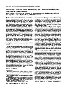
Figure 4: Sagittal MR image shows entire spine with autolabeled intervertebral disks (yellow). The red dot corresponds to the manual assignment of the C2-3 centroid. The vertebrae themselves may also be autolabeled (labeling omitted here for clarity). Additionally, given the three-dimensional coordinates generated by the algorithm, disks or vertebral bodies can also be labeled in any subsequent imaging plane, provided no gross interimaging patient movement has occurred.
Figure 5: Sagittal MR image in a patient with 23 mobilepresacralvertebrae(ie,thosecephalictothefirst sacralizedvertebra),ratherthan24,demonstratesneuroradiologistconcordantautolabelingofthefirst22intervertebraldisks(yellow).ASSISTsoftwaretermsthefirst sevenvertebraeC1throughC7,thenext12vertebraeT1 throughT12,andthesubsequentfivevertebraeL1 throughL5,regardlessofribbearingstatusorpossible sacralization.Alternatively,inthispatientwithonly23 mobilepresacralvertebrae,the22nddiskmaybelabeled L4-S1andtheunlabeleddiminutivediskimmediately caudal,S1-2(23rddiskinthispatient). 259
TECHNICAL DEVELOPMENTS: Automated Spine Survey Iterative Scan Technique
Figure 7
Figure 6
Weiss et al
was concordant with neuroradiologist assignments in 26 (96%) of 27 cases; the single error was related to a severely collapsed vertebra (Fig 8a). The modified algorithm was concordant in all 50 cases (100%), which included the original 27 studies plus the 23 subsequent studies, despite the presence of congenital variations (Figs 5, 6), postoperative changes (Fig 7), and prominent disk or vertebral pathologic conditions (Fig 8b) in this patient population. None of the 50 studies required technologist input of more than a single interspace (disk C2-3), although the algorithm provides such an iterative pathway if necessary (Fig 1b; Appendix). Run on a personal computer with a 2.8GHz processor, the algorithm took 1 minute 47 seconds (⫾ 20 seconds [standard deviation]) of central processing unit time (range, 58 seconds to 52 minutes 47 seconds) to identify and label all intervertebral disks or vertebrae.
Discussion
Figure 6: Sagittal MR image in a patient with 25 potentially mobile presacral vertebrae demonstrates neuroradiologist concordant autolabeling of the first 23 intervertebral disks (yellow). The 23rd disk is labeled L5-S1, with apparent lumbarization noted on this and adjacent sagittal images. The unlabeled 24th disk is prominent and may be termed lumbarized S1-S2 or simply S1-2. 260
Figure 7: Sagittal image in a patient with surgically fused L4-5 interspace and associated artifact from metallic cage demonstrates neuroradiologist concordant labeling of all 23 interspaces (yellow), including a good approximation of the L4-5 disk.
Although the ASSIST algorithm was successful in all 50 patients we studied, the seven-section sagittal acquisition would be expected to fail in patients with severe scoliosis because there would be insufficient spine coverage. As such, if prominent scoliosis is suspected, more sagittal sections could be autoprescribed; the cost of this is proportionately increased imaging time. The automated disk-vertebrae numbering algorithm was designed to accept any number of sagittal sections; however, its accuracy in patients with severe scoliosis is unknown, and parameter modifications might be required. Additionally, ASSIST was designed and tested only on an adult population. As a consequence, the algorithm would likely require additional testing and modifications for optimal performance in a pediatric population. While the disk detection algorithm presently requires manual input of the most cephalic disk, C2-3, we are currently developing computer detection of this interspace to achieve complete automation. The C2-3 disk may be readily discerned, based on several unique feaRadiology: Volume 239: Number 1—April 2006
TECHNICAL DEVELOPMENTS: Automated Spine Survey Iterative Scan Technique
tures, on midline sagittal images of the head with a 22–24-cm FOV or on ASSIST images of cervicothoracic spine with a 35-cm FOV. These unique features include the characteristic shape of the C2 vertebra and the relatively constant relationship to the skull base and cervicomedullary junction. We are also working to optimize the ASSIST algorithm for other magnet platforms. Moreover, we hope to adapt the algorithm for computed tomography (CT), substituting automated sagittal CT spine reconstructions for the direct sagittal MR acquisitions. The foregoing may facilitate automated temporal comparisons, multimodal multiparametric spinal analysis, and optimized intervention. Additionally, autoreformation of volumetric CT or MR spine data along the true sagittal, coronal, or transverse axes of the vertebral bodies and disks may potentially facilitate the radiologist’s image interpretation. As previously suggested for MR imaging and CT of the brain (9,10), direct MR imager or CT scanner integration and related algorithms for computer-assisted diagnosis could eventually enable “real-time” automated spine image analysis and iterative scan prescriptions. For example, optimally angled transverse oblique sequencing could be autoprescribed through all interspaces or disks demonstrating abnormal morphology or signal intensity characteristics on the ASSIST or subsequent sagittal studies (11). By streamlining and converting Matlab code to C⫹⫹, processing time might be substantially shortened. Coupled with an integrated head and spine array coil, rapid computer automated iterative prescription and analysis of the entire neuroaxis may be possible. Our study had limitations. It was retrospective in design, and the sample size was relatively small. The modified computer labeling algorithm was tested on only 23 de nouveau studies, the other 27 having been utilized for algorithm refinement. As such, a larger prospective investigation may be more informative. In conclusion, by using autoprescribed subminute, submillimeter inplane resolution total spine localizer studies, cervical, thoracic, and lumbar Radiology: Volume 239: Number 1—April 2006
Weiss et al
Figure 8
Figure 8: Sagittal MR images in a patient with vertebral planus of T10. (a) Image mislabeled by using the initial algorithm (in first batch of 27 studies). Note the initial algorithm required two seed points (in red). (b) Neuroradiologist concordant autolabeled image after algorithm modifications, including adjustment of Gaussian filters. The modified algorithm required only a single seed point (in red).
vertebrae and disks can be readily identified and definitively numbered by means of visual inspection or semiautomated computer algorithm.
the search line inferiorly on the basis of the estimated position (Ex,y) of the missing disk(s):
E共 xj,yj兲 ⫽ 共xj⫺1, yj⫺1兲
Appendix As diagramed in Figure 1b, if 23 disks are not identified, the program extends
冘
j⫺1
⫹ ha共xj⫺1, yj⫺1兲 䡠
1
hs共x, y兲 , ha共x, y兲 261
TECHNICAL DEVELOPMENTS: Automated Spine Survey Iterative Scan Technique
where ha is the average vertebral height from a 22 subject training set, hs is the vertebral height from the subject in question, and xj and yj are the anteriorposterior and superior-inferior coordinates of the j-th disk. The program searches for local maxima along this line extension and 24 adjacent parallel lines. Iteration continues as long as 23 disks are not selected. If 22 disks are selected, the algorithm will determine whether the last identified level (disk L4-5) satisfies criteria for the terminal presacral interspace suggesting a congenital variant with 23 rather than the typical 24 mobile presacral vertebrae. To be considered a terminal disk, the centroid of the 22nd disk must be less than one-fourth the distance from the centroid of the 21st disk and the estimated position (Ex,y) of the 22nd disk derived from the equation above. Additionally, the centroid must lie posterior to the centroid of the 21st disk, and the slope of the 22nd disk’s major anterior-posterior axis must be positive and greater than that of the 21st disk. If the terminal disk criteria are not met, the position of the 23rd (L5-S1) disk is estimated by using the above equation, and the search constraints are refined. If the 23rd disk is still not identified, the disk is presumed to be severely degenerated or to have under-
262
gone surgery, and the estimated position for disk L5-S1 will be accepted. In reference to Figure 1b, if less than 22 disks are identified with use of the algorithm, the technologist will be instructed to approximate (ie, click on) the centroid of the last disk. The technologist’s selection becomes definitive terminal criteria for the last disk. The “combine data” step from Figure 1a is repeated and, if necessary, the “search for additional disks” step is repeated as well. If at least 22 disks (including the technologist’s selections) are still not obtained, the algorithm prints an error message and notifies the technologist. Acknowledgments: The authors gratefully thank Set Shahbabian, MD, and the fine staff at WestImage MRI Center (Cincinnati, Ohio), especially Lynn Adamson, RTR (MR), for her helpful expertise in ASSIST sequence implementation and for providing consecutive batches of deidentified patient studies.
References 1. Porter RW. Spinal surgery and alleged medical negligence. J R Coll Surg Edinb 1997;42: 376 –380. 2. Bergman R, Afifi A, Miyauchi R. Skeletal systems: peculiar thoracic vertebrae. In: Opus V, ed. Illustrated encyclopedia of human anatomic variation. Iowa City, Iowa: University of Iowa, 2004. 3. Goodkin R, Laska LL. Wrong disc space level
Weiss et al
surgery: medicolegal implications. Surg Neurol 2004;61:323–342. 4. Wilson C, Brown D, Najarian K, Hanley EN, Gruber HE. Computer aided vertebral visualization and analysis: a methodology using the sand rat, a small animal model of disc degeneration. BMC Musculoskelet Disord 2003;4:4. 5. Smyth PP, Taylor CJ, Adams JE. Vertebral shape: automatic measurement with active shape models. Radiology 1999;211:571–578. 6. Summers RM. Road maps for advancement of radiologic computer-aided detection in the 21st century. Radiology 2003;229:11–13. 7. Tench CR, Morgan PS, Constantinescu CS. Measurement of cervical spinal cord crosssectional area by MRI using edge detection and partial volume correction. J Magn Reson Imaging 2005;21:197–203. 8. Gonzalez RC, Woods RE, Eddins SL. Morphological image processing. In: Gonzalez RC, ed. Digital image processing with Matlab. 2nd ed. Cambridge, England: Pearson, 2003; 373. 9. Weiss KL, Storrs J, Weiss JL, Strub W. CT brain prescriptions in Talairach space: a new clinical standard. AJNR Am J Neuroradiol 2004;25:233–237. 10. Weiss KL, Pan H, Storrs J, et al. Clinical brain MR imaging prescriptions in Talairach space: technologist- and computer-driven methods. AJNR Am J Neuroradiol 2003;24: 922–929. 11. Demaerel P, Sunaert S, Wilms G. Sequences and techniques in spinal MR imaging. JBRBTR 2003;86:221–222.
Radiology: Volume 239: Number 1—April 2006