Automatic construction of reactive control systems using symbolic machine learning
CLAUDE SAMMUT Department of Artificial Intelligence, University of New South Wales, Sydney Australia 2052 (email:
[email protected])
Abstract This paper reviews a number of applications of Machine Learning to industrial control problems. We take the point of view of trying to automatically build rule-based reactive systems for tasks that, if performed by humans, would require a high degree of skill, yet are generally performed without thinking. Such skills are said to be sub-cognitive. While this might seem restrictive, most human skill is executed subconsciously and only becomes conscious when an unfamiliar circumstance is encountered. This kind of skill lends itself well to representation by a reactive system, that is, one that does not create a detailed model of the world, but rather, attempts to match percepts with actions in a very direct manner.
1 . Introduction Traditional control theory requires a mathematical model of a physical process to predict its behaviour so that appropriate control decisions can be determined. Unfortunately, many processes are either too complicated to model accurately or insufficient information is available about the process’ environment. In such cases, heuristic methods often prove useful. But where do the heuristics come from? They may be hand-crafted, based on the knowledge of experts, but this is often not possible since many control skills are sub-cognitive, that is, they are performed without thinking and without any conscious knowledge of the skill. For this reason, machine learning plays an important role in building knowledge-based control systems. How a dynamic system is controlled depends very much on the time scales involved. A good example of a highly dynamic system is an aircraft. Suppose we wish to control a large plane, such as a 747. This system is so large that the response time for a control decision may be quite long. Say, for example, that the pilot wishes to lower the flaps on a landing approach. Depending on the angle of the flaps, this may take quite a few seconds. Given the inertia of such a large aircraft, the effect of 1
lowering the flaps is further delayed. In fact, piloting a large commercial aircraft, under normal circumstances, requires a high degree of conscious planning and forethought. On the other hand, suppose we are piloting a highly responsive aircraft, such as a fighter or aerobatics plane. In this case, the aircraft responds to control decisions very quickly and therefore, much of the pilot’s decision making must be correspondingly fast, in fact, so fast that conscious thought is not possible. Many of our skills are sub-cognitive, just like the fighter pilot’s skill. In 1911, the mathematical philosopher A.N. Whitehead wrote: It is a profoundly erroneous truism ... that we should cultivate the habit of thinking what we are doing. The precise opposite is the case. Civilisation advances by extending the number of important operations which we can perform without thinking about them.
In this paper, we are concerned, not with the conscious planning and control that a 747 pilot might engage in, but rather in the subconscious control of a fighter pilot. Such skills are not limited to exotic domains. When we do not have good model of a dynamic system, we usually resort to “seat-of-the-pants” control. As an example, consider a system such as a container crane. Very large gantry cranes are used to transport heavy loads, on a swinging rope, from the dock to a ship and vice versa. Because of their non-linear nature, traditional control theory is unable to provide optimal control strategies to maximise the throughput of these cranes, yet some human operators are known to perform much better than others and better than automated systems. Somehow, they have acquired a skill that enables them to perform very efficiently, yet they are unable to articulate that skill because it is sub-cognitive. Human sub-cognitive skills are “tacit” in the sense that the owner of such a skill is unaware of its mode of operation. However, a skilled human operator of a plant is usually conscious of the goals and sub-goals he or she is attempting to achieve. Each of these goals may be served by a separate sub-cognitive procedure. Machine-executable forms of such sub-cognitive skills can be used to simplify the construction of practical control systems by introducing a “multi-agent” architecture where low-level agents may be regarded as expert solvers for a particular problem. A chairman, who has global access to the problem-solving environment, selectively invokes members of a committee of specialists each of which has access to a different, very limited, part of the environment. The chairman embodies explicit knowledge that is easily articulated and therefore can be hand-crafted. The specialists implement low-level real-time control skills that, in a human, are not performed at a conscious level and therefore cannot be articulated. To create this kind of knowledge, each agent may be separately derived by inductive learning of production rules from recorded human performance of the skilled task. Complex control skills in humans are built of components which their possessors cannot explicitly communicate. However, given sufficient sampling of subarticulate input-output, machine learning programs can construct rules which result in behaviours similar to those of the original exemplars (Michie, 1986). These “clones”, i.e. exemplar-derived agents, are in effect, symbolic representations of subsymbolic behaviours.
2
In this paper, we first look briefly at heuristic control systems and at how control skills can be specified by a symbolic representation. We then review systems that learn such control rules. Note that we confine ourselves to a discussion of techniques for learning symbolic representations. One of the primary aims of the work surveyed is to produce explicit descriptions of sub-cognitive skills that can be read and understood. There are two reasons for this: one is that such explicit representations may shed light on the nature of the skill; the second is that the skill’s description may lead to improved training methods. There is a considerable body of literature on neural, genetic and reinforcement learning for control problems. While much of this work has been extremely productive, we do not include it in our survey since the output from these algorithms are often difficult to interpret.
2 . Reactive Procedures Tacit skills can be represented by “situation-action” rules. We illustrate this with a new formalism developed by Nilsson (1994). A teleo-reactive(T-R) sequence is an agent control program that directs the agent toward a goal (hence teleo) in a manner that takes into account changing environmental circumstances (hence reactive). In its simplest form, it consist of an ordered set of production rules.
Two T-R procedures for controlling a mobile robot are shown below: goto(Loc) position = Loc heading = course(position, Loc) otherwise
→ → →
nil move rotate
amble(Loc) position = Loc clear_path(position, Loc) otherwise
→ → →
nil goto(Loc) amble(new_point(position, Loc))
The left hand side of a production rule consists of tests on sensor data and the right hand side consists of calls to action procedures. The first rule of the goto procedure simply states that if the robot is at the desired location then do nothing. If the heading of the robot is the same as the course required to reach the desired location then move forward, otherwise rotate. These production rules are continuously evaluated in the order they are written. As the robot rotates, the heading is continuously compared with the required course. When they are the same, the second production rule takes priority, so rotation stops and the robot moves forward. If the robot drifts off course then the third rule will be invoked until the heading is correct again. The amble procedure describes a simple plan for obstacle avoidance. If the robot is at the desired location then do nothing. If there is a clear path from the current position to the desired location then go to that location, otherwise determine a new point to one
3
Table 1. Yaw Control Rule Yaw positive Yaw ok Yaw negative
1 thrust 4 1 thrust 2 full thrust Yaw rate very negative
no thrust
1 – thrust 4
1 – thrust 2
no thrust
no thrust
no thrust
1 thrust 2 Yaw rate negative
1 thrust 4 Yaw rate ok
no thrust Yaw rate positive
– full thrust 1 – thrust 2 1 – thrust 4 Yaw rate very positive
side of the obstacle and call amble recursively. Some procedures, either sensor or motor, are built it. For example, the current heading may be determined by reference to an onboard compass which is accomplished by special purpose code. Primitive actions include move, rotate, etc. Actions, whether primitive or user defined, can be used in planning provided that additional information is available, namely, the preconditions necessary for an action to achieve a goal, the postconditions of the action and side effects, such as conditions which become true or false after performing the action. In effect, the current situation is used as an index into a set of pre-arranged action sequences. If the rules cover all possible situations in which an agent can find itself, these plans are said to be universal (Schoppers, 1987). We give a simple, but practical example of a universal plan in the following section. 2.1.
Satellite Control
If the attitude of a satellite in Earth orbit is to be kept stable by means of thrusters, the control system must contend with many unknown factors. For example, although very thin, the Earth's atmosphere can extend many hundreds of kilometres into space. At different times, the solar wind can cause the atmosphere's density to change, thus altering the drag on the space craft. Indeed, the solar wind, itself highly variable, can affect the satellite's attitude. These are factors which earth-bound designers cannot predict, and even after nearly four decades of space flight, attitude control is still a major problem. Sammut and Michie (1991) developed a strategy for firing roll, pitch and yaw thrusters by using a simple table look up, which corresponds very closely to Nilsson’s T-R paradigm. We illustrate this with the yaw table, reproduced in Table 1. Pitch and roll have similar control strategies. Using a high-fidelity simulator of a space craft, Sammut and Michie found that although roll, pitch and yaw are coupled, the control systems for each can be separated. Each axis is discretised so that when the state variables indicate that the system falls in a particular table entry or box, the appropriate action is taken. Roll, pitch and yaw are treated independently, but even though a torque in one direction can cause precession in another, the rules implicitly correct for interactions. Originally, Sammut and Michie used pure bang-bang control. While this was able to control the satellite, it wasted fuel
4
and caused unnecessary accelerations. The strategy shown in Table 1 is fuel efficient and relatively smooth. Discretisation of the state space was a trivial matter. The designers of the spacecraft indicated regions of optimum performance; acceptable performance and unacceptable performance. These specifications were used to set the boundaries of the boxes. This application illustrates some advantages of a reactive control system. Because system builders are often unable to predict variations in environment, a system may be designed so that it responds in reaction to the current situation rather than following a pre-defined plan which may become inappropriate when conditions change. The attitude control problem is one in which it is relatively easy to cover all expected situations, provided that all the thrusters are operating normally. Later we will discuss how failures can be handled. In this example, it was possible to write comprehensive control rules, however, an obvious difficulty with reactive control systems, especially universal ones, is that number of rules required may become impossibly large in some domains. How can we anticipate all possible circumstances? Where will all of these rules come from? Machine Learning provides one answer.
3 . Learning Situation-Action Rules by Behavioural Cloning Behavioural cloning seeks to build situation-action rules by learning from the traces of a skilled operator’s behaviour. Thus, if a human is capable of performing some task, rather than ask him or her to explain how the task was performed, we ask to be shown how. Machine learning is used to create a symbolic description of the skill where introspection by the human operator fails because the task is performed without thinking. The first demonstration of behavioural cloning was by Michie, Bain and Hayes-Michie (1990) on the task of pole balancing. Since then, a number of practical applications have been developed. The method of behavioural cloning is best understood by looking at some of these applications. 3.1.
Learning to Fly
Sammut, Hurst, Kedzier and Michie (1992) modified a flight simulation program to log the actions taken by a human subject as he or she flies an aircraft. The log file is used to create the input to an induction program. The quality of the output from the induction program is tested by running the simulator in autopilot mode where the autopilot code is derived from the decision tree formed by induction. The central control mechanism of the simulator is a loop that interrogates the aircraft controls and updates the state of the simulation according to a set of equations of motion. Before repeating the loop, the instruments in the display are updated.
5
3.1.1. Logging Flight Information The display update was modified so that when the pilot performs a control action by moving the control stick or changing the thrust or flaps settings, the state of the simulation is written to a log file. Three subjects each ‘flew’ 30 times. At the start of a flight, the aircraft points North, down the runway. The subject is required to fly a well-defined flight plan that consists of the following manoeuvres: 1. Take off and fly to an altitude of 2,000 feet. 2. Level out and fly to a distance of 32,000 feet from the starting point. 3. Turn right to a compass heading of approximately 330˚. The subjects were actually told to head toward a particular point in the scenery that corresponds to that heading. 4. At a North/South distance of 42,000 feet, turn left to head back towards the runway. The scenery contains grid marks on the ground. The starting point for the turn is when the last grid line was reached. This corresponds to about 42,000 feet. The turn is considered complete when the azimuth is between 140˚ and 180˚. 5. Line up on the runway. The aircraft was considered to be lined up when the aircraft's azimuth is less than 5˚ off the heading of the runway and the twist is less that ±10˚ from horizontal. 6. Descend to the runway, keeping in line. The subjects were given the hint that they should have an ‘aiming point’ near the beginning of the runway. 7. Land on the runway. During a flight, up to 1,000 control actions can be recorded. With three pilots and 30 flights each, the complete data set consists of about 90,000 events. The data recorded in each event are: on_ground g_limit wing_stall twist elevation azimuth roll_speed elevation_speed azimuth_speed airspeed climbspeed E/W distance altitude N/S distance fuel rollers elevator rudder thrust
boolean: is the plane on the ground? boolean: have we exceeded the plane’s g limit boolean: has the plane stalled? integer: 0 to 360˚ (in tenths of a degree, see below) integer: 0 to 360˚ (in tenths of a degree, see below) integer: 0 to 360˚ (in tenths of a degree, see below) integer: 0 to 360˚ (in tenths of a degree per second) integer: 0 to 360˚ (in tenths of a degree per second) integer: 0 to 360˚ (in tenths of a degree per second) integer: (in knots) integer: (feet per second) real: E/W distance from centre of runway (in feet) real: (in feet) real: N/S distance from northern end of runway (in feet) integer: (in pounds) real: ±4.3 real: ±3.0 real: not used integer: 0 to 100% 6
flaps
integer: 0˚, 10˚ or 20˚
The elevation of the aircraft is the angle of the nose relative to the horizon. The azimuth is the aircraft’s compass heading and the twist is the angle of the wings relative to the horizon. The elevator angle is changed by pushing the mouse forward (positive) or back (negative). The rollers are changed by pushing the mouse left (positive) or right (negative). Thrust and flaps are incremented and decremented in fixed steps by keystrokes. The angular effects of the elevator and rollers are cumulative. For example, in straight and level flight, if the stick is pushed left, the aircraft will roll anti-clockwise. The aircraft will continue rolling until the stick is centred. The thrust and flaps settings are absolute. When an event is recorded, the state of the simulation at the instant that an action is performed could be output. However, there is always a delay in response to a stimulus, so ideally we should output the state of the simulation when the stimulus occurred along with the action that was performed some time later in response to the stimulus. But how do we know what the stimulus was? Unfortunately there is no way of knowing. Human responses to sudden piloting stimuli can vary considerably but they take at least one second. For example, while flying, the pilot usually anticipates where the aircraft will be in the near future and prepares the response before the stimulus occurs. Each time the simulator passes through its main control loop, the current state of the simulation is stored in a circular buffer. An estimate is made of how many loops are executed each second. When a control action is performed, the action is output, along with the state of the simulation as it was some time before. How much earlier is determined by the size of the buffer. 3.1.2. Data Analysis Quinlan’s C4.5 (Quinlan, 1993) program was used to generate flight rules from the data. Even though induction programs can save an enormous amount of human effort in analysing data, in real applications it is usually necessary for the user to spend some time preparing the data. The learning task was simplified by restricting induction to one set of pilot data at a time. Thus, an autopilot has been constructed for each of the three subjects who generated training data. The reason for separating pilot data is that each pilot can fly the same flight plan in different ways. For example, straight and level flight can be maintained by adjusting the throttle. When an airplane’s elevation is zero, it can still climb since higher speeds increase lift. Adjusting the throttle to maintain a steady altitude is the preferred way of achieving straight and level flight. However, another way of maintaining constant altitude is to make regular adjustments to the elevators causing the airplane to pitch up or down. The data from each flight were segmented into the seven stages described previously. In the flight plan described, the pilot must achieve several, successive goals, corresponding to the end of each stage. Each stage requires a different
7
manoeuvre. Having already defined the sub-tasks and told the human subjects what they are, the learning program was given the same advantage. In each stage four separate decision trees are constructed, one for each of the elevator, rollers, thrust and flaps. A program filters the flight logs generating four input files for the induction program. The attributes of a training example are the flight parameters described earlier. The dependent variable or class value is the attribute describing a control action. Thus, when generating a decision tree for flaps, the flaps column is treated as the class value and the other columns in the data file, including the settings of the elevator, rollers and thrust, are treated as ordinary attributes. Attributes that are not control variables are subject to a delay, as described in the previous section. C4.5 expects class values to be discrete but the values for elevator, rollers, thrust and flaps are numeric. A preprocessor breaks up the action settings into sub-ranges that can be given discrete labels. Sub-ranges are chosen by analysing the frequency of occurrence of action values. This analysis must be done for each pilot to correctly reflect differing flying styles. There are two disadvantages to this method. One is that if the sub-ranges are poorly chosen, the rules generated will use controls that are too fine or too coarse. Secondly, C4.5 has no concept of ordered class values, so classes cannot be combined during the construction of the decision tree. An event is recorded when there is a change in one of the control settings. A change is determined by keeping the previous state of the simulation in a buffer. If any of the control settings are different in the current state, a change is recognised. This mechanism has the unwanted side-effect of recording all the intermediate values when a control setting is changed through a wide range of values. For example, the effects of the elevator and rollers are cumulative. If we want to bank the aircraft to the left, the stick will be pushed left for a short time and then centred, since keeping it left will cause the airplane to roll. Thus, the stick will be centred after most elevator or roller actions. This means that many low elevator and roller values will be recorded as the stick is pushed out and returned to the centre position. To ensure that records of low elevator and roller values do not swamp the other data, another filter program removes all but the steady points and extreme points in stick movement. Control engineers are familiar with this kind of filtering. In their terms, the graph of a control’s values is differentiated and only the values at the zero crossings of the derivative are kept. 3.1.3. Generating the Autopilot After processing the data as described above, they can be submitted to C4.5 to be summarised as rules that can be executed in a controller. Decision tree algorithms are made noise tolerant by introducing pruning. If the data contain noise, then many of the branches in a decision tree will be created to classify bad data. The effects of noise can be reduced by removing branches near the leaves of the tree. This can either be done by not growing those branches when there are insufficient data or by cutting back branches when their removal does not decrease classification accuracy.
8
The flight data are very noisy, so decision trees are generated using conservative setting for pruning and then tested in the simulator. Pruning levels are gradually increased until the rule ‘breaks’, ie. it is no longer able to control the plane correctly. This procedure results in the smallest, and thus most readable, rule the succeeds in accomplishing the flight goal. 3.1.4. Linking the Autopilot with the Simulator To test the induced rules, they are used as the code for a autopilot. A post-processor converts C4.5’s decision trees into if-statements in C so that they can be incorporated into the flight simulator easily. Hand-crafted C code determines which stage the flight has reached and decides when to change stages. The appropriate rules for each stage are then selected in a switch statement. Each stage has four, independent if-statements, one for each action. When the data from the human pilots were recorded, a delay to account for human response time was included. Since the rules were derived from these data, their effects should be delayed by the same amount as was used when the data were recorded. When a rule fires, instead of letting it effect a control setting directly, the rule’s output value is stored in a circular buffer. There is one for each of the four controls. The value used for the control setting is one of the previous values in the buffer. A lag constant defines how far to go back into the buffer to get the control setting. The size of the buffer must be set to give a lag that approximates the lag when the data were recorded. Rules could set control values instantaneously as if, say, the stick were moved with infinite speed from one position to another. Clearly this is unrealistic. When control values are taken from the delay buffer, they enter another circular buffer. The controls are set to the average of the values in the buffer. This ensures that controls change smoothly. The larger the buffer, the more gentle are the control changes. 3.1.5. Flying on Autopilot An example of the rules created by cloning is the elevator take-off rule generated from one pilot’s data: elevation > 4 : level_pitch elevation 114 : right_roll_1 = 585 if Y1 >= 5865
One of the immediate benefits of this analysis was that it revealed that many of the measure variables were irrelevant to determining the yield of the plant. The next step was to work out the correct settings for the control variables so that they achieve the values of the measured variables that result in high yield. It was found that only three measured variables were significant in determining yield. Training examples were collected for each of these three variables. The attributes of the examples were the values of the eleven control variables for the plant and the class value was the measure variable. Thus, decision trees were built which would predict the value of each measured variable, given the control settings for the plant. An example of the decision tree for Y1 is shown below. if (C4 < 172.5) if (C2 < 134.5) if (C7 < 294.5) Y1 = low else Y1 = ok else Y1 = ok else if (C2 < 127.5) Y1 = low
15
A
X
B C
Y
D
Z
F
Controls
X
Goals Y
Z
A B C D F
0.8 0.0 0.0 0.4 0.1
0.1 0.4 0.7 0.4 0.2
0.2 0.4 0.2 0.0 0.6
Effector set allocations SET
X
Y
Z
UE
—
—
—
ME
A
C
F
SE
D,F
B,D,F,A
B,A,C
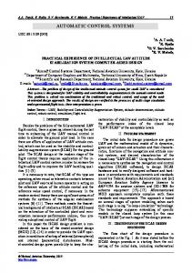
Figure 4. (a) An example of a plant (b) perceived influences between control inputs and output goals (c) agent’s effector view of system else if (C8 < 143.5) if (C2 < 131.0) Y1 = low else Y1 = ok else Y1 is ok
Note that the Y1 values have been discretised into the ranges ‘low’, ‘ok’ and ‘high’. Again, the decision tree is converted into a set of rules: Y1 Y1 Y1 Y1 Y1 Y1 Y1
= = = = = = =
low ok ok low low ok ok
if if if if if if if
C4 C4 C4 C4 C4 C4 C4
< 172.5 & C2 < 134.5 & < 172.5 & C2 < 134.5 & < 172.5 & C2 >= 134.5 >= 172.5 & C2 < 127.5 >= 172.5 & C2 >= 134.5 >= 172.5 & C2 >= 134.5 >= 172.5 & C2 >= 134.5
C7 < 294.5 C7 >= 294.5 & C8 < 143.5 & C2 < 131 & C8 < 143.5 & C2 >= 131 & C8 >= 143.5
We now have two sets of rules. The first tells the control system the desired values of the plant outputs (or measured variables). The second set of rules tells the control system the values of the plant inputs (or control variables) required to obtain the desired outputs. From these, it is relatively straight forward to build the complete control system. Leech’s work demonstrates that goal-directed behaviour for reactive systems can be learned. However, the method used for the chemical plant cannot be directly applied to other control tasks such as flying or driving container cranes, since the concept of “yield” is not present. In the next section, we describe a semi-automatic method for building goal-directed controllers. 4.2.
CHURPS
CHURPS (or Compressed Heuristic Universal Reaction Planners) were developed by Stirling (1995) as a method for capturing human control knowledge. Particular emphasis was placed on building robust controllers that can even tolerate actuator failures. Where behavioural cloning attempts to avoid questioning an expert on his or here behaviour, Stirling’s approach is to obtain from the expert a starting point from which a
16
controller can be generated automatically. The expert is asked to supply “influence factors”. These are numbers in the range 0 to 1 which indicate how directly a control input affects an output goal. This is illustrated in Figure 4. Here, control action, A, has an influence of 0.8 on goal variable, X. This means that, A, is the main effector that influences that value of the measure variable, X. Action, A, also has lesser effects on variables Y and Z. A is also classed as the main effector for goal variable X. From the influence matrix, control actions are grouped into three sets for each goal variable: A Unique Effector (UE) is the only effector which has any influence on a goal variable. A Maximal Effector (ME) has the greatest influence over a particular goal variable. However, other effectors may have secondary influence over that goal variable. Secondary Effectors (SE) are all the effectors for a goal variable, except the main effector The UE, ME and SE sets are used by Stirling’s Control Plan generator CPG algorithm to generate operational control plans. The algorithm assigns appropriate effectors to control various output goals in order of importance. Informally, the CPG algorithm is: Create an agenda of goals which consist of output variables whose values deviate from a set point. The agenda may be ordered by the importance of the goal variable. while the agenda is not empty select the next goal if deviation is small then attempt to assign an effector in the order, UE, SE, ME. if deviation is large then attempt to assign an effector in the order, UE, ME, SE. examine influencee’s of the effector that was invoked and add them to the agenda. remove selected goal
The selection of an effector is qualified by the following conditions: • A controller which is a UE of one goal should not be used as an ME or SE for another goal. • When choosing an SE, it should be one that has the least side-effects on other goal variables. This procedure tells us which control actions can be used to effect the desired change in the goal variables. However, the actions may be executed in a variety of ways. Stirling gives the following example. Suppose variables X, Y and Z in Figure 4, are near their desired values. We now wish to double the value of Y while maintaining X and Z at their current levels. Following the CPG algorithm: 1. Y initially appears as the only goal on the agenda. 2. Y had no unique effector and since the required deviation is large, we try to apply an ME, namely, C. 3. Since C also affects Z, Z is appended to the agenda.
17
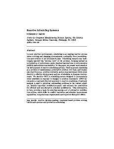
Influence Matrix
CPG Plans
C4.5
PD Controller
Figure 5. CHURPS Architecture 4. Since Y is the current goal and an effector has successfully been assigned to it, Y is removed from the agenda. 5. Z becomes the current goal. Let us assume that the deviation in Z is small. 6. We attempt to assign as SE to control Z. B is selected since C is already assigned to control Y. A could have been selected, but it would have a side effect on variable X, causing a further expansion in the agenda. 7. The agenda is now empty and terminates with the assignments {Y/C, Z/B}, which can be read as “control goal Y to its desired state via effector C and control goal Z to its desired state via effector B”. This plan can be executed sequentially, by first using C to bring Y to its desired value and then using C to bring Z to its desired value. A loop would sample the plant at regular intervals terminating each phase when the desired value is reached. Alternatively, both actions could be executed in parallel. The first strategy corresponds to one that might be followed by a novice, whereas experts tend to combine well practised behaviours since they do not have to think about them. As a model of human sub-cognitive skill, the CPG method does not capture the notion that pre-planning is not normally carried out. That is, a skilled operator would not think through the various influences of controls on outputs, but would act on the basis of experience. This is usually faster than first trying to produce a plan and then executing it. To try to simulate this kind of expert behaviour, Stirling used the CPG algorithm as a plan generator which exhaustively generated all combinations of actions for different possible situations. This large database of plans was then compressed by applying machine learning to produce a set of heuristics for controlling the plant. The architecture of this system is shown in Figure 5. To create the input to the learning system (Quinlan’s C4.5) each goal variable was considered to have either a zero, small or large deviation from its desired value. All combinations of these deviations were used as initial conditions for the CPG algorithm. In addition, Stirling considered the possibility that one or more control action could fail. Thus plans were also produced, for all of the combinations of deviations and all combinations of effector failures. In a style somewhat similar to Leech’s, Stirling devised a “goal centred” control strategy in which learning was used to identify the effectors that are required to control particular goal variables. Thus if there is a deviation in goal variable Y, a decision tree is built to identify the most appropriate control action, including circumstances in which some control actions may not be available due to failure. An example of a tree for goal variable X, is shown below: if (control A is active)
18
if (deviation of X is non-zero) use control A else if (control D is inactive) use control A else if (control F is active) use control D else use control A else if (control D is active) use control D else use control F
Once the control action has been selected, a conventional proportional controller is used to actually attain the desired value. The CHURPS method has been successfully used to control a simulated Sendzimir cold rolling mill in a steel plant. It has also been used to control the same aircraft simulation used by Sammut et al. Like that work, the flight was broken into seven stages. However, one major difference is that CHURPS required the goals of each stage to be much more carefully specified than in behavioural cloning. For example, the original specification of stage 4, the left turn was: At a North/South distance of 42,000 feet, turn left to head back to the runway. The turn is considered complete when the compass heading is between 140˚ and 180˚
In CHURPS this is translated to At a North/South distance of 42,000 feet, establish a roll of 25˚ ±2˚ and maintain pitch at 3 ±5˚, airspeed at 100 knots ±40 knots and climb speed at 1 ft/sec ±5 ft/sec. When the plane’s compass heading is between 140˚ and 180˚, return the roll to 0˚ ±2˚ and maintain all other variables at the same values.
Recalling that the influence matrix was constructed by hand, CHURPS requires much more help from the human expert than behavioural cloning. However, so far, CHURPS have produced smoother and more robust controllers. The question arises, can some combination of behavioural cloning and the CHURPS method used to produce robust controllers requiring minimal advice from the expert? In preliminary experiments, Bain (Bain & Sammut, 1995) has shown that it is possible to use induction on behavioural traces to produce a controller similar in style to CHURPS and Leech’s method. The purpose of the influence matrix is to determine which control inputs should be assigned to which goal outputs. Suppose we have a behavioural trace of a pilot flying an aircraft, rather than try to map situations to actions directly, an induction algorithm can be applied to determine the effect of controls on output variables. For example, if we wish to know how to control climb speed, we may preprocess the behavioural trace to distinguish changes in climb speed as the class variable that we wish to predict. The control actions available become the attributes of the example (along with the other measured variables). The result is a decision tree which tells us which control to apply to affect a change in climb speed under different circumstances. The CPG algorithm can then proceed as before.
19
A more difficult problem, which is still being investigated is how the goal structure of a complex task can also be learned by induction.
5 . Conclusion In this paper, we have reviewed recent research in the application of symbolic machine learning techniques to the problem of automatically building controllers for dynamic systems. By capturing traces of human behaviour in such tasks, it is possible to build controllers that are efficient and robust. This type of learning has been applied in a variety of domains including the control of chemical processes, manufacturing, scheduling, and autopiloting of diverse apparatus including aircraft and cranes. Learning control by observing expert behaviour is best suited to tasks where there is little articulated knowledge about the problem but there is a source of tacit knowledge in the expert. This approach contrasts with other systems that can learn control tasks but which assume that background knowledge is available. For example DeJong’s (1994, 1995) Explanation-Based Control system builds a controller by using a domain specific theory of qualitative physics to explain an observed trace and then generalise to a control strategy. Behavioural cloning starts with no such knowledge. Pure behavioural cloning attempts to capture simple situation-action rules from traces. However, situation-action rules have their limitations in that there must be a rule for every likely situation, otherwise the control will not be robust. One of the major directions for future research is the coupling of goal-directed behaviour with pure cloning. This has the effect of breaking a complex task in to more manageable subtasks. Several promising methods were for achieving this synthesis were discussed but it remains for future research to demonstrate their success.
References Arentz, D. (1994) The Effect of Disturbances in Behavioural Cloning. Computer Engineering Thesis, School of Computer Science and Engineering, University of New South Wales. Bain, M., & Sammut, C. (1995). A framework for behavioural cloning. In K. Furukawa, D. Michie, & S. Muggleton (Eds.), Machine Intelligence 15. Oxford: Oxford University Press. Benson, S., & Nilsson, N. J. (1995). Reacting, planning and learning in an autonomous agent. In K. Furukawa, D. Michie, & S. Muggleton (Eds.), Machine Intelligence 15. Oxford: Oxford University Press. DeJong, G. (1994). Learning to plan in continuous domains. Artificial Intelligence, 64(1), 71-141.
20
DeJong, G. (1995). A case study of explanation-based control. In A. Prieditis & S. Russell (Ed.), International Conference on Machine Learning, (pp. 167-175). Tahoe City, California: Morgan Kaufmann. Kerr, R.M. & Kibira, D. (1994). Intelligent reactive scheduling by human learning and machine induction. IFAC Conference on Intelligent Manufacturing Systems. Vienna. Leech, W. J. (1986). A Rule Based Process Control Method with Feedback. In Proceedings of the ISA/86. Research Triangle Park, NC 27709: The Instrumentation Society of America. Michie, D. (1986). The superarticulacy phenomenon in the context of software manufacture. Proceedings of the Royal Society of London, A 405, 185-212. Reproduced in D. Partridge and Y. Wilks (1992) The Foundations of Artificial Intelligence, Cambridge University Press, pp 411-439. Michie, D., Bain, M., & Hayes-Michie, J. E. (1990). Cognitive models from subcognitive skills. In M. Grimble, S. McGhee, & P. Mowforth (Eds.), Knowledge-base Systems in Industrial Control. Peter Peregrinus. Michie, D., & Camacho, R. (1994). Building symbolic representations of intuitive realtime skill from performance data. In K. Furakawa, D. Michie, & S. Muggleton (Eds.), Machine Intelligence 13. (pp. 385-418). Oxford: The Clarendon Press, OUP. Nilsson, N. J. (1994). Teleo-Reactive programs for agent control. Journal of Artificial Intelligence Research, 1, 139-158. Quinlan, J. R. (1993). C4.5: Programs for Machine Learning. San Mateo, CA: Morgan Kaufmann. Sammut, C., & Michie, D. (1991). Controlling a ‘Black-Box’ simulation of a spacecraft. AI Magazine, 12(1), 56-63. Sammut, C., Hurst, S., Kedzier, D., & Michie, D. (1992). Learning to fly. In D. Sleeman & P. Edwards (Ed.), Proceedings of the Ninth International Conference on Machine Learning, Aberdeen: Morgan Kaufmann. Schoppers, M. J. (1987). Universal plans for reactive robots in unpredictable domains. In Proceedings of IJCAI-87. San Francisco: Morgan Kaufmann. Stirling, D., & Sevinc, S. (1992). Automated operation of complex machinery using plans extraced from numerical models: Towards adaptive control of a stainless steel cold rolling mill. In Proceedings of the 5th Australian Joint Conference on Artificial Intelligence, Stirling, D. (1995) CHURPs: Compressed Heuristic Universal Reaction Planners. Ph.D. Thesis, University of Sydney.
21
Urbancˇicˇ, T., & Bratko, I. (1994). Reconstructing human skill with machine learning. In A. Cohn (Ed.), Proceedings of the 11th Europena Conference on Artificial Intelligence, John Wiley & Sons. Whitehead, A. N. (1911). An Introduction to Mathematics.
22