scheduling, wired and wireless communication, local clocks, ... to simulation of the wireless communication at the radio .... The drawback is that infrastructure.
Proceedings of the 44th IEEE Conference on Decision and Control, and the European Control Conference 2005 Seville, Spain, December 12-15, 2005
MoA14.4
Simulation of Wireless Networked Control Systems ˚ en Martin Andersson, Dan Henriksson, Anton Cervin and Karl-Erik Arz´ Department of Automatic Control Lund University Box 118, SE-221 00 Lund, Sweden {mandersson,dan,anton,karlerik}@control.lth.se Abstract— Embedded systems are becoming increasingly networked and are deployed in application areas that require close interaction with their physical environment. Examples include distributed mobile agents and wireless sensor/actuator networks. The complexity of these applications make cosimulation a necessary tool during system development. This paper presents a simulation environment that facilitates simulation of computer nodes and communication networks interacting with the continuous-time dynamics of the real world. Features of the simulator include interrupt handling, task scheduling, wired and wireless communication, local clocks, dynamic voltage scaling, and battery-driven operation. Two simulation case studies are presented: a simple communication scenario and a mobile robot soccer game.
I. I NTRODUCTION Sensor/actuator networks and mobile robots are application areas for embedded real-time systems where wireless communication plays a vital role. The computing and communication resources in these types of applications are often severely limited, making integrated design approaches important. Another common characteristic of these systems is that they interact with their environment. One example is a sensor network that monitors the presence of moving objects in some environment. Other examples are mobile robots moving around in the environment or sensor/actuator networks that implement networked control loops. Simulation is a powerful technique that can be used at several stages of system development. In order to support the applications at hand, co-simulation facilities are crucial. It should be possible to simultaneously simulate the computations that take place within the nodes, the wireless communication between the nodes, the sensor and actuator dynamics, the dynamics of the mobile robots, and the dynamics of the environment, including the physical systems under control. In order to model the limited resources correctly, the simulation model must be quite realistic. For example, it should be possible to simulate the timing effects of context switches and interrupts in a multi-tasking real-time kernel implementing the control logic of the nodes. It should also be possible to simulate the effects of collisions and contention in the wireless MAC layers. Due to simulation time and size constraints, it is at the same time important that the simulation model is not too detailed. For example, simulating the computations on a source code level, instruction for instruction, would be overly costly. The same applies to simulation of the wireless communication at the radio
0-7803-9568-9/05/$20.00 ©2005 IEEE
interface level or on the bit transmission level. There are a number of simulation environments available for networked systems, see the related work section at the end for an overview. However, the majority of these only simulate the wireless communication and the node computations. Hence, something more is needed. TrueTime [1], [2] is a cosimulation tool that has been developed at Lund University since 1999. By using TrueTime it is possible to simulate the temporal behavior of computer nodes and communication networks that interact with the physical environment. The network support has so far been restricted to wired networks. In this paper the new wireless network block is presented. This, in combination with the already present features, makes it possible to concurrently simulate all the aspects described above. This opens up a wide range of new application types for simulation, e.g., teams of collaborating or competing mobile robots interacting with their environment. Another example could be sensor networks with mobile or stationary nodes communicating via wireless ad-hoc networks internally and through a gateway node to back-end servers using wired networks. A. Outline of the paper Section II gives a brief overview of TrueTime. The new wireless network block is described in Section III. At the time of writing this only supports IEEE 802.11b WLAN communication. However, it is currently being extended to also support Bluetooth (IEEE 802.15) and Zigbee [3]. Section IV describes two other new simulator features, local clocks and modeling of battery-driven operation. Two simulation case studies are presented in Section V. The first is a simple wireless communication scenario. The second shows how a mobile robot soccer game can be simulated, inspired by the well-known RoboCup [4]. An overview of related work is given in Section VI, and the paper concludes with Section VII. II. T HE T RUE T IME S IMULATOR TrueTime is based on Simulink [5], the graphical simulation environment of MATLAB, and consists of computer and network blocks as shown in the block library in Figure 1. The TrueTime blocks are connected with ordinary Simulink blocks to form a real-time control system. The main feature of TrueTime is the possibility of co-simulation of the interaction between the real-world continuous dynamics and
476
A. Modeling of a Wireless Network
Fig. 1.
The TrueTime block library.
the computer architecture in the form of task execution and network communication. The TrueTime computer block executes user-defined tasks and interrupt handlers representing, e.g., I/O tasks, control algorithms, and network drivers. The scheduling policy of the individual computer blocks is arbitrary and decided by the user. Execution times of tasks and interrupt handlers can be modeled as constant, random, or data-dependent. Furthermore, TrueTime allows simulation of context switching and task synchronization using events or monitors. The TrueTime network blocks distribute messages between computer nodes according to a chosen network model. Communication models supported by the wired network block are: CSMA/CD (e.g. Ethernet), CSMA/AMP (e.g. CAN), Round Robin (e.g. Token Bus), FDMA, TDMA (e.g. TTP), and Switched Ethernet. Only the properties related to the communication timing are modeled, i.e., the simulation is not performed on bit level. The focus of this paper is on the wireless network modeling and simulation. For more details on the computer and wired network blocks, see [1], [2]. TrueTime 1.3 (including the new features) is available for download at http://www.control.lth.se/˜dan/truetime. III. T HE T RUE T IME W IRELESS N ETWORK There are many differences between wireless and wired networks in general, all of which make it interesting to simulate the timing characteristics of a wireless network as compared to a wired one. Some notable differences are related to the physical medium and attenuation of radio signals, and various amounts of interference from other nodes. Wireless devices are also often limited in that thay can not send and receive at the same time. The following sections will describe the wireless network modeling, the implementation of the IEEE 802.11b WLAN standard, and the interface of the wireless block within TrueTime. Again it should be noted, that the scope of the wireless block (and the TrueTime environment as a whole), is to simulate the main properties related to the timing characteristics and not to be a full fledged wireless network simulator. Consequently, the simulation of network messages is not done on the bit or radio interface level.
Wireless networks can be divided into two groups, infrastructure based networks and ad-hoc networks. Infrastructure based networks are very common in WLANs of today. Typically all communication takes place between nodes and access points and there is no direct communication between nodes. This makes it easy for the access point to control the medium access, in a manner similar to switched Ethernet. It is also rather straight-forward to let the access point perform routing between different networks when the node is not within its signal reach. The drawback is that infrastructure based networks are not so flexible. Ad-hoc networks on the other hand are very flexible, and do not need any infrastructure at all to work. In such networks, nodes can communicate directly to each other and there is no need for access points. This on the other hand makes routing a bit harder because no central intelligence exists. In a wireless network, radio is often used as the physical transportation layer for the signal, and then an antenna is needed. There exists a number of different antenna models. One often used theoretical model of an antenna is the isotropic one. This is simply a point in space which radiates equal amounts of power in all directions. In reality though, all antennas have more or less directive effects and many antennas are even designed to have such effects. It is common that radio stations are built such that they can not send and receive at the same time. As a consequence, it is not possible for a sending station to hear if another station starts to send during its own sending. Duplex stations can be built, but it requires more complex hardware. In a wireless network there is always the question of pathloss. The signal power is always much lower in the receiver than in the sender. Parts of this comes from the fact that they do not have a guarded medium and therefore the radio signal power is spread in all or some directions depending on the antenna being used. Obstacles such as buildings, trees, fog, snow and rain will also affect the signal level in the receiver. In a wireless network, the air can be considered a shared medium and therefore interference from other terminals must be taken into account. It can also happen that nodes that are not able to hear each other when they are sending, disturb each others transmissions in a receiving node. This is often referred to as the problem with hidden terminals. B. Modeling of the IEEE 802.11b Protocol Currently, the TrueTime wireless network block simulates medium access and packet transmission, i.e., the medium access control (MAC) sub-layer of the IEEE 802.11 reference model. 802.11b is used in many laptops and mobile devices of today, and is because of its heavy use a good candidate to include in a simulator. The 802.11b standard is quite complex and is described in [6] and [7]. A more condensed presentation can be found in [8]. The MAC schemes of 802.11b are the same as in ordinary 802.11, therefore the simulation model presented here is valid for 802.11 as well. The model presented simulates:
477
Direct sequence spread spectrum (DSSS) physical layer (PHY). Other non-supported PHY layers of 802.11 are frequency hopping spread spectrum (FHSS) and infrared (IR). • Ad-hoc wireless networks, as opposed to infrastructurebased ones. • Isotropic antenna. • Unable to send and receive at the same time. 1 • Path loss of radio signals modeled as da where d is the distance in meters and a is a suitably chosen parameter to model the environment. • The mandatory basic access method based on CSMA/CA. • Interference from other terminals (shared medium). • ACK messages on the MAC protocol level. A package transmission is modeled like this: The node that wants to transmit a packet checks to see if the medium is idle. The transmission may proceed, if the medium is found to be idle, and has stayed so for a time specified in the standard (50 µs when using DSSS). If, on the other hand, the medium is found to be busy, a random back-off time is chosen and decremented in the same way as when colliding (described in the end of this section). When a node starts to transmit, its relative position to all other nodes in the same network is calculated, and the signal level in all those nodes are calculated according to the path-loss formula d1a . The signal is assumed to be possible to detect, if the signal level in the receiving node is larger than a configurable threshold (receiver signal threshold). If this is the case, then the signal-to-noise ratio (SNR) is calculated and used to statistically find the block error rate (BLER). Note that all other transmissions add to the background noise when calculating the SNR. The BLER, together with the size of the message, is used to calculate the number of bit errors in the message and if this number is lower than another threshold (error coding threshold), then it is assumed that the channel coding scheme is able to fully reconstruct the message. If there are (already) ongoing transmissions from other nodes to the receiving node and their respective SNRs are lower than the new one, then all those messages are marked as collided. Also, if there are other ongoing transmissions which the currently sending node reaches with its transmission, then those messages may be marked as collided as well. Note that a sending node does not know if its message is colliding, therefore ACK messages are sent on the MAC protocol layer. From the perspective of the sending node, lost messages and message collisions are the same, i.e., no ACK is received. If no ACK is received during a certain configurable time, the message is retransmitted after waiting a random back-off time within a contention window. The contention window size is doubled for every retransmission of a certain message. The back-off timer is stopped if the medium is busy, or if it has not been idle for at least a time specified by the protocol (50 µs when using DSSS). There are only a certain configurable number of retransmissions before the sender gives up on the message and it is not retransmitted anymore. •
C. The TrueTime Wireless Block Interface The structure of the wireless block as seen from a user point of view is very similar to the wired network block. The main difference between the wired network block and the wireless one is that the x and y coordinates of the simulated computers are made available to the wireless block with two vector input ports as seen in the block library in Figure 1. The wireless block is event-driven, i.e., when a node tries to transmit a packet, the packet is put in an input buffer and a trigger signal is sent to the block on the Snd port. When the simulated transmission of the package is finished, the packet is put in a buffer at the receiving node and a new trigger signal is sent to the receiving node on the Rcv port. A packet contains information about the sending and receiving computer node, arbitrary user data, and the packet length. The wireless block is configured through a block dialogue. The available options consist of: Network number. A unique identifier for the wireless network block. Number of nodes. Number of nodes connected to the network, affects the size of Snd, Rcv and Schedule inputs and outputs of the wireless block. Data rate. Transmission speed of the network. Minimum frame size. A message shorter than this number will be padded. Transmit power. According to the standard this is limited to a maximum of 1000 mW in USA, 100 mW in Europe and 10 mW in Japan. Receiver signal threshold. If the received energy is above this value, then the medium is regarded as busy. Path-loss exponent. The number a in d1a . ACK timeout. The time a sending node will wait for an ACK message before retransmiting it. Retry limit. The maximum number of times a node will try to retransmit a message before giving up. Error coding threshold. A number in the interval [0, 1] which defines the percentage of block errors in a message that the coding can handle. For example, certain coding schemes can fully reconstruct a message if it has less than 10% block errors. IV. OTHER N EW S IMULATION F EATURES A. Local Clocks Having independent clock representations with respect to a global time will facilitate simulation of problems related to clock drift in asynchronous systems and failure in the clock synchronization for synchronized systems. The local clocks are manipulated by specifying time offsets and drifts, which is typically done during the initialization phase for each node. An ideal clock is obtained by choosing those values to be zero. The timing primitives in TrueTime that are affected by the change in clock representation are; ttSleep, ttSleepUntil, ttCurrentTime, and ttCreateTimer, which all operate on the local clocks in the node.
478
B. Power Consumption The power constraints of networked embedded systems make it desirable to model power consumption. Therefore, we have recently incorporated models of power devices (batteries) into the TrueTime framework. This makes it possible to model and evaluate power management strategies at different levels of the system for energy-efficient implementations. This includes dynamic voltage scaling algorithms and energy-aware scheduling and communication protocols. As a means for this TrueTime also supports the possibility for dynamic changes of the CPU speed in the different nodes. Each node has its own battery block which is connected in a feedback loop with the computer block. The inputs to the battery block are the CPU speed, transmission and receiving activity, and sensor and actuator power. The battery itself is modeled as an integrator, fed by the sum of the battery inputs. The output of the battery is fed to the computer block, and as this level drops to zero all node activity stops.
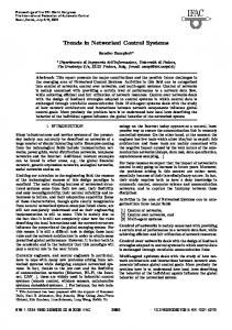
a)
b)
Fig. 2. The two configurations considered in the example of Section V-A. Node 1, 2, and 3 all send to node 4. Node 1 is too far away to reach the destination in the first setup, whereas in the second setup all three sending nodes interfere. The circles around the nodes show the distance at which the transmitted signal is no longer possible to detect (receiver signal threshold). Transmission schedule (high=sending, medium=waiting, low=idle) 3.5
Node 3 3
V. S IMULATION C ASE S TUDIES
2.5
Node 2
The TrueTime simulation environment for networked embedded systems will now be demonstrated in two simulation scenarios. The first simple scenario is intended to demonstrate the wireless communication model and the impact of interfering nodes and physical locations on the communication timing. The other example is more elaborate and show the use of TrueTime in a research areas that is currently receiving much attention in the real-time systems community, distributed control of mobile agents.
2
1.5
Node 1 1 0.015
0.02
0.025
0.03
a)
Time (s) Transmission schedule (high=sending, medium=waiting, low=idle) 3.5
Node 3 3
A. A Simple Communication Scenario 2.5
This setup contains four nodes communicating over the wireless network. The example is intended to show how the distance between sender and receiver and interference from other sending nodes affect the communication timing. Two situations will be described with the geographic locations of the nodes displayed in Figure 2. In the first setup (labeled a) in the figure), node 1 is far away from the others and therefore its signal level will be too low to receive in the other nodes. This also means that node 1 will not be able to disturb the transmissions of the other nodes. The circle around each node denotes the distance at which the power of the original signal has been reduced to the threshold value. In this simulation, the transmit power was 100 mW, the threshold 2 mW and the path loss exponent was set to 2. In the second setup, node 1 has moved considerably closer and is now within the reach of all other nodes. In both setups, nodes 1, 2, and 3 send periodic messages to the receiver node (node 4). Closeups of the resulting network schedules can be seen in Figure 3. The network schedule has the following representation. Low means that the node is idle and has nothing to send. Medium corresponds to that the node is waiting to transmit, but for some reason has not started yet, i.e., the net is busy or it is counting down its back-off timer from previous collisions. And finally, high means that the node is sending. Note that a node does not
Node 2 2
1.5
Node 1 1 2.315
2.32
2.325
Time (s)
2.33
b)
Fig. 3. Close-ups of the network schedules corresponding to the two configurations described in Figure 2.
know that its message has collided until it does not receive an ACK message from the receiver. The top plot of Figure 3 shows the transmission in the first setup. At time 0.02 all three nodes start to send at the same time, and at the time when they have finished sending +ACKtimeout they conclude that for some reason their messages were not received properly. All nodes then choose a randomized back-off time (according to the CSMA/CA policy) and nodes 2 and 3 both manage to get their messages sent to the receiver without further collisions. Node 1, however, is trying to send its message over and over again. This depends on the fact that it is too far away from the intended receiver node and therefore does not get an ACK message back. So it sends its message, waits the ACKtimeout and then it tries to send again after waiting
479
an additional back-off time. This behavior continues until the maximum retry limit, which is set to five in this example, has been reached and then it drops the message. In the second setup the transmissions of all three sending nodes collide (as seen in the bottom plot of Figure 3), and they all choose random back-off times before re-transmitting and getting their messages through.
A/D
3 Snd
Snd Interrupts Schedule
1 Rcv 2 y
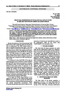
B. RoboCup This setup is inspired by the well-known RoboCup project [4]. This project aims at, by the year of 2050, having a team of fully autonomous robots win against the human world soccer champions. RoboCup 2005 will be held in Osaka, Japan. This soccer cup consists of five leagues: the simulation league, the small size league, the middle size league, the 4legged league, and the humanoid league. This example involves two teams consisting of five players each, playing soccer against each other on a simulated play field. All the players are modeled as TrueTime computer blocks and the communication between them is performed via the new wireless network block presented in this paper. The example shows that TrueTime is a good tool for evaluating high-level strategies in the field of distributed intelligence, autonomous agents and multi-agent collaboration. 1) Mote Modeling: Each soccer playing robot, mote, is modeled by a TrueTime computer and simple dynamics for its planar motion. The Simulink subsystem representing a mote is shown in Figure 4. In this simplified model it is assumed that the mote moves independently in the x- and y-directions. The mote has two D/A outputs representing the currents to the motors. The dynamics between motor current 1 , with and position is given by the transfer function s(s+3.5) 1 s+3.5 being the transfer function between motor current and velocity. By integrating the velocity we obtain the position. It is further assumed that both the positions and the corresponding velocities are directly measurable, and thus the mote has four A/D inputs for these signals. In a more realistic setup, some filtering of the position measurements would have been required to obtain velocity estimates. The Schedule output is used to monitor the execution within the computer, and the mote communicates through the TrueTime wireless network using the Snd and Rcv ports. 2) Visualization and High-level Coordination: The Simulink model of the soccer game consists of ten motes (two teams of five motes each) modeled according to the previous section. The x- and y-coordinates of each mote are also fed into a MATLAB S-function responsible of animating the game using 2D-graphics. Within this framework, it is easy to evaluate different high-level strategies to coordinate the motes in the two teams. Both centralized and distributed intelligence may be considered. In the following we assume a centralized strategy where a master node is coordinating the movements of the motes in each team. The master has full sensing capability of both the ball position and the position of the individual motes. In a real setup this would, e.g., correspond to a camera monitoring the playing field and sending the information to
em
D/A
1 x
Rcv
Monitors
Schedule
TrueTime Kernel 1
1 s
s+3.5
1 s
s+3.5
1
Fig. 4. A model of a mobile robot in TrueTime, consisting of a TrueTime computer for code execution and communication and continuoustime dynamics for its motion.
the master node. The master node sends commands to motes in the team and receives back responses of completed tasks. Commands can be e.g. shoot, pass, dribble etc. 3) Local Sensing and Control: The local intelligence of the individual motes can be chosen to incorporate different true hardware configurations and physical devices. It is, e.g., straight-forward to model sensors such as proximity sensors and on-board vision systems. The controller and its implementation may also be arbitrarily advanced. The implementation in this case is intended to mimic a tiny embedded device without any RTOS support. The position controllers of the motes are implemented in interrupt handlers connected to hardware timers. Simple proportional control is used to follow velocity trajectories to reach reference positions provided by the master node. When a mote has the ball it either dribbles in the direction of the opposing goal or shoots if it is sufficiently close. When dribbling, the mote may also receive commands from the master to pass the ball in the direction of a team mate. Figure 5 shows screen shots from an attacking combination. VI. R ELATED W ORK There exists a large number of general network simulators today. One of the most well-known is ns-2 [9], which is a discrete-event simulator for both wired and wireless networks with support for, e.g., TCP, UDP, routing, and multicast protocols. It also supports simple movement models for mobile applications. Another discrete-event computer network simulator is OMNeT++ [10]. It contains detailed IP, TCP, and FDDI protocol models and several other simulation models (file system simulator, Ethernet, framework for simulation of mobility, etc.). Compared to these simulators, the network simulation part in Truetime is far more simplistic. However, the strength of TrueTime is the co-simulation facilities that makes it possible to simulate the latency-related aspects of the network communication in combination with the node computations and the dynamics of the physical environment. Rather than basing the co-simulation tool on a general network simulator and then try to extend this with additional co-simulation facilities, the approach has been to base
480
Fig. 5.
A sequence of screen shots from a successful attacking combination in the simulated RoboCup application.
the co-simulation tool on a powerful simulator for general dynamical systems, i.e., Simulink, and then add support for simulation of real-time kernels and the latency aspects of network communication to this. An additional advantage of this approach is the possibility to make use of the wide range of toolboxes that are available for Matlab/Simulink. For example, support for virtual reality animation. There are also some network simulators geared towards the sensor network domain. TOSSIM [11] compiles directly from TinyOS code and scales very well. Network in a box (NAB) [12] is another simulator for large-scale sensor networks. Antoher example is J-Sim, a general compositional simulation environment that includes a generalized packet switched network model that may be used to simulate wireless LANs and sensor network [13]. Again, these types of simulators generally lack the possibility to simulate continuous-time dynamics and to simulate the inner workings of the nodes at the thread and interrupt handler level, that are present in TrueTime. A few other tools have been developed that support cosimulation of real-time computing systems and control systems. RTSIM [14] has a module that allows system dynamics to be simulated in parallel with scheduling algorithms. XILO [15] supports the simulation of system dynamics, CAN networks, and priority-preemptive scheduling. Ptolemy II is a general purpose multi-domain modeling and simulation environment that includes a continuous-time domain, and a simple RTOS domain. Recently it has been extended in the sensor network direction [16]. In [17] a co-simulation environment based on ns-2 is presented. The ns-2 simulator has been extended with an ODE-solver for dynamical simulations of the controller units and the environment. However, this tool lacks support for real-time kernel simulation. VII. C ONCLUSIONS This paper has presented a simulation environment for mobile wireless networked embedded systems. The tool is focused on co-simulation, where the computer architecture in the form of computer nodes and communication networks are simulated in parallel with continuous-time dynamics modeling the physical environment. The paper has described the modeling and implementation of the IEEE 802.11b standard for wireless communication
within the TrueTime framework. Other new features are simulation of local clocks, and power consumption within the individual nodes. Two examples have been presented: a simple communication scenario and a mobile robot soccer game. ACKNOWLEDGMENTS The work has been sponsored by the EU/IST FP6 integrated project RUNES, the EU/IST FP6 network of excellence ARTIST2, the Swedish Foundation for Strategic Research via the program FLEXCON, and the Swedish Research Council. R EFERENCES ˚ en, [1] A. Cervin, D. Henriksson, B. Lincoln, J. Eker, and K.-E. Arz´ “How does control timing affect performance?” IEEE Control Systems Magazine, vol. 23, no. 3, pp. 16–30, June 2003. [2] M. Andersson, D. Henriksson, and A. Cervin, TrueTime 1.3— Reference Manual, Department of Automatic Control, Lund University, Sweden, June 2005. [3] The ZigBee Alliance, Home page, http://www.zigbee.org, 2004. [4] The RoboCup Federation, “RoboCup,” Home page, http://www.robocup.org, 2004. [5] The Mathworks, Simulink: A Program for Simulating Dynamic Systems – User’s Guide. Natick, MA: The MathWorks Inc., 2001. [6] “ANSI/IEEE Std 802.11,” 1999. [7] “IEEE Std 802.11b,” 1999. [8] J. Schiller, Mobile Communications Second Edition. AddissonWesley, 2003, iSBN 0 321 12381 6. [9] “Ns-2,” Home page: http://www.isi.edu/nsnam/ns/index.html, 2004. [10] “Omnet++,” Home page: http://www.omnetpp.org, 2004. [11] P. Levis, N. Lee, M. Welsh, and D. Culler, “TOSSIM: accurate and scalable simulation of entire TinyOS applications,” in Proceedings of the 1st international conference on Embedded networked sensor systems, Los Angeles, CA, USA, 2003, pp. 126–137. [12] “NAB (Network in A Box),” Home page: http://nab.epfl.ch/, 2004. [13] H.-Y. Tyan, “Design, realization and evaluation of a component-based compositional software architecture for network simulation,” Ph.D. dissertation, Ohio State University, 2002. [14] L. Palopoli, L. Abeni, and G. Buttazzo, “Real-time control system analysis: An integrated approach,” in Proceedings of the 21st IEEE Real-Time Systems Symposium, Orlando, Florida, December 2000. [15] J. El-Khoury and M. Trngren, “Towards a toolset for architectural design of distributed real-time control systems,” in Proceedings of the 22nd IEEE Real-Time Systems Symposium, London, England, December 2001. [16] P. Baldwin, S. Kohli, E. A. Lee, X. Liu, and Y. Zhao, “Modeling of sensor nets in ptolemy II,” in IPSN’04: Proceedings of the third international symposium on Information processing in sensor networks. ACM Press, 2004, pp. 359–368. [17] M. Branicky, V. Liberatore, and S. M. Phillips, “Networked control systems co-simulation for co-design,” in Proc. American Control Conference, 2003.
481