O. Yaniv Faculty of Engineering Department of Electrical Engineering Systems, Tel Aviv University, Tel Aviv 69978, Israel e-mail:
[email protected]
M. Nagurka Department of Mechanical and Industrial Engineering, Marquette University, Milwaukee, WI 53201 e-mail:
[email protected]
Automatic Loop Shaping of Structured Controllers Satisfying QFT Performance This paper presents a robust noniterative algorithm for the design of controllers of a given structure satisfying frequency-dependent sensitivity specifications. The method is well suited for automatic loop shaping, particularly in the context of Quantitative Feedback Theory (QFT), and offers several advantages, including (i) it can be applied to unstructured uncertain plants, be they stable, unstable or nonminimum phase, (ii) it can be used to design a satisfactory controller of a given structure for plants which are typically difficult to control, such as highly underdamped plants, and (iii) it is suited for design problems incorporating hard restrictions such as bounds on the high-frequency gain or damping of a notch filter. It is assumed that the designer has some idea of the controller structure appropriate for the loop shaping problem. 关DOI: 10.1115/1.1985441兴 Keywords: Automatic Loop Shaping, Robust Control, QFT, Linear Feedback Systems
1
Introduction
Loop shaping is often a key step in the process of designing a controller. Although the skill can be gained easily, loop shaping is not simple, and many are not familiar with it. Moreover, in complicated applications it may be hard even for one skilled in the art. Automatic loop shaping 共ALS兲 streamlines the design process and offers the possibility of finding a controller faster and better than that obtainable by a knowledgeable person. ALS techniques can be split into two major categories: 共i兲 those based on optimization algorithms, such as convex, nonconvex, and genetic algorithms 共GAs兲, and 共ii兲 those based on calculating a dense set of controllers from which the optimal solution can be chosen. The first approach affords more freedom in the sense that the controller structure is not fixed 共although it is restricted in some way兲. In the second approach the controller structure is fixed and the design challenge is in selecting free parameters that offer optimal performance and satisfy constraints. Researchers have pursued both approaches. An early effort towards the goal of achieving an ALS algorithm was reported by Gera and Horowitz 关1兴. They describe a semiALS process, i.e., an iterative approach in which the designer sequentially adds an element to the open-loop transfer function to force it to pass a given straight line in the Nichols chart. Being semi-automatic, the outcome may be a very high-order controller and the solution may be far from optimal. The technique was automated by Ballance and Gawthrop 关2兴. Chait et al. 关3兴 offer an alternate ALS algorithm. They present a sufficient, constructive condition for converting the original problem into a convex optimization formulation. The main drawback of their technique is that the poles of the controller are fixed and are not part of the optimization process. Thompson and Nwokah 关4兴 proposed a constrained, finite dimensional, nonlinear programming approach that starts from an assumed initial QFT controller. The technique was extended by Thompson 关5兴 to QFT bounds for combined parametric and nonparametric as well as weighted control efforts. A GA for ALS was proposed by Garcia-Sanz and Guillen 关6兴 with the advantage over previous work being that no initial controller is Contributed by the Dynamic Systems, Measurement, and Control Division of THE AMERICAN SOCIETY OF MECHANICAL ENGINEERS for publication in the ASME JOURNAL OF DYNAMIC SYSTEMS, MEASUREMENT, AND CONTROL. Manuscript received: April 22, 2004. Final revision: September 26, 2004. Associate Editor: Yossi Chait.
472 / Vol. 127, SEPTEMBER 2005
needed. However, it suffers from the drawbacks of GAs, such as being computationally demanding 共GAs are inherently parallel algorithms and therefore best suited to multiple-processor machines兲, not guaranteeing a global optimum without unlimited computational effort, and being user intensive 共knowing what one wants helps to setup the problem in a way that increases the chance of getting a better solution兲. ALS algorithms falling into the second category have been pursued by Zolotas and Halikias 关7兴, Besson and Shenton 关8兴, and others. Zolotas and Halikias 关7兴 describe an ALS method for proportional-integral-derivative 共PID兲 controllers based on searching over a dense set of controllers. Their technique is efficient for two parameter controllers and a small number of bounds. Fransson et al. 关9兴 adopted a nonconvex optimization method to design PID controllers for QFT-type problems, while considering the tradeoffs among low, mid, and high frequencies specifications. This paper describes an approach that also fits within the second ALS category. It is based on a noniterative solution for the design of a two-parameter controller. As will be shown, it can be extended to design controllers of more than two parameters by cycling through free parameters two-at-a-time. In practice, it means solving for the optimal controller with two free parameters while fixing all other parameters, and then repeating this process over a reasonable range of values of the fixed parameters. As opposed to the existing optimization techniques, the approach proposed here is based on a set of closed form solutions, giving a set of controllers. Moreover, it can be used for the design of controllers with notch filters and can handle gain uncertainty without additional computational burden. The paper is organized as follows: The problem is defined in Sec. 2 and the design method for two parameter controllers is given in Sec. 3. An extension for the design of controllers having more than two parameters is provided in Sec. 4. Section 5 addresses the design of two degree-of-freedom QFT problems.
2
The Loop Shaping Problems
The QFT loop shaping problem for single-input single-output 共SISO兲 or multi-input single-output 共MISO兲 systems or the sequential QFT loop shaping problem for multi-input multi-output 共MIMO兲 systems can be described as follows: Find a stabilizing
Copyright © 2005 by ASME
Transactions of the ASME
Fig. 1 A MISO feedback system
linear time-invariant 共LTI兲 controller G共s兲 such that the feedback system whose open-loop transfer function, L共s兲 = P0共s兲G共s兲, satisfies L共j兲 = P0共j兲G共j兲 僆 R共兲,
PI controller, G = a共1 / s + b兲. A PD controller augmented with a low-pass filter, G = a共1 + bs兲 / 共1 + s / p兲, is the result of choosing P1 = P / 共1 + s / p兲 and P2 / P1 = s. These and more structures will be used later to design controllers of more than two parameters. The 共a , b兲 pairs satisfying inequality 共4兲 form a set in the twodimensional plane. An analytic algorithm for calculating its boundary was presented by Yaniv and Nagurka 关11兴 for a PI controller and constant M and in Ref. 关12兴 for the open-loop case having the form of Eq. 共3兲 with constant M. The algorithm for M共兲 is developed next. Substituting 共3兲 into 共4兲 gives 共where the dependence on is suppressed for convenience兲 U + a共U1 + bU2兲 + a2共V1 + bV2 + b2V3兲 艌 0,
∀艌0
where P0共s兲 denotes a single plant and R共兲, for any frequency , denotes a set in the complex plane. Moreover, for a given controller structure, an optimal controller can be defined in any way. In QFT the practice is to take the controller whose high-frequencygain 共HFG兲 is minimum. 共The HFG of G共s兲 is k = lims→⬁G共s兲se where e is the excess of poles over zeros of G.兲 It is required to design a controller whose HFG is as close to the optimal controller as possible. For MISO QFT problems, the boundary of the set R共兲 can for some specifications be given by the QFT bounds 共or Horowitz bounds 关10兴兲 of the following problem. Consider the feedback system depicted schematically in Fig. 1 and described by the equations,
where U = 1 − 1/M 2, V1 = 兩P1兩2,
共1兲
where P is an LTI plant known to belong to a set 兵P其, G is an LTI controller, r = 0 and d is a disturbance which may depend on P 僆 兵P其. The problem is to design an LTI controller, G共s兲, such that for any P 僆 兵P其, the system 共1兲 is stable and for a given function, M共 , P兲, the transfer function y共s兲 / d共s兲 is bounded by
冏
∀艌0
and
P 僆 兵P其. 共2兲
R共兲 is the set in the complex plane such that P0共j兲G共j兲 僆 R共兲, if and only if, 共2兲 is satisfied for 共where P0 is a chosen member of 兵P其 and R共兲 depends on P0兲. Note that since M can be a function of the plant, Eq. 共2兲 can represent disturbances at the plant input and disturbances as a function of the plant.
3 Automatic Loop Shaping for a Two-parameter Controller Let P1共s兲, P2共s兲 be a pair of plants known to belong to a set of pairs 兵共P1共s兲 , P2共s兲兲其 and define an open-loop transfer function L共s兲 for the pair P1共s兲, P2共s兲 by L共s兲 = a共P1共s兲 + bP2共s兲兲
共3兲
where a and b are scalars. The design problem is to find the a, b pairs such that
冏
冏
1 艋 M共P1共j兲, P2共j兲, 兲; 1 + L共j兲 ∀艌0
for all pairs
U2 = 2 · Real共P2兲,
V2 = 2 · Real共P1 P*2兲,
V3 = 兩P2兩2 .
˙ + a共U ˙ + bU ˙ 兲 + a2共V˙ + bV˙ + b2V˙ 兲 = 0. U 1 2 1 2 3
u = G共Fr − y兲,
冏
U1 = 2 · Real共P1兲,
For an 共a , b兲 pair which is on the boundary of the allowed 共a , b兲 pairs, there exists and a pair P1,P2 僆 兵共P1 , P2兲其 such that 共5兲 is an equality. 共Otherwise, 共a , b兲 can only be an internal point of the set solving the inequality 共5兲.兲 At that particular , the left-hand side of 共5兲 is zero and minimum, and thus its derivative with respect to is zero. 共The latter observation was also used in Ref. 关13兴 to design a controller for maximum a.兲 Thus, at that particular 共dot denotes derivative with respect to 兲
y = Pu + d
1 艋 M共, P兲, 1 + P共j兲G共j兲
∀ 艌 0 共5兲
P1, P2 僆 兵共P1, P2兲其. 共4兲
In order to identify the open-loop transfer function of the system of Fig. 1, L共s兲 = PG is written as L共s兲 = aP1共s兲共1 + bP2共s兲 / P1共s兲兲. Thus, choosing P1 = P and P2 / P1 = s gives a PD controller, G = a共1 + bs兲; choosing P1 = P / s and P2 / P1 = 1 gives the Journal of Dynamic Systems, Measurement, and Control
共6兲
Solving the equality of 共5兲 and 共6兲 for a gives a=
=
˙ U − UU ˙ − 共− U ˙ U + UU ˙ 兲b U 1 1 2 2 ˙ V − UV˙ + 共U ˙ V − UV˙ 兲b + 共U ˙ V − UV˙ 兲b2 U 1 1 2 2 3 3 A + Bb . C + Db + Eb2
共7兲
Substituting 共7兲 into the equality of 共5兲 gives a fourth-order polynomial equation for b x 4b 4 + x 3b 3 + x 2b 2 + x 1b + x 0 = 0
共8兲
whose coefficients are the following functions of x4 = UE2 + B2V3 − BU2E x3 = 共− U2E + 2BV3兲A − BU1E + 2UDE + B2V2 − BU2D x2 = A2V3 + 共2BV2 − U2D − U1E兲A + B2V1 − BU1D + UD2 + 2UCE − BU2C x1 = A2V2 + 共− U1D − U2C + 2BV1兲A + 2UCD − BU1C x0 = − AU1C + UC2 + A2V1 . The boundary of the allowed 共a , b兲 region can be calculated using the following procedure. 共1兲 Choose a pair P1,P2 僆 兵共P1 , P2兲其. 共2兲 Choose and solve 共8兲 for b. Noting that b has four solutions 共for a given 兲, pick the real solution 共s兲. 共3兲 For each b found in 共2兲, solve inequality 共4兲 to find all a, b pairs for which the resulting closed-loop system is stable and 共4兲 is satisfied for all P1,P2 僆 兵共P1 , P1兲其. The result for each b is one or more intervals since inequality 共4兲 is a set of quadratic inequalities involving a. 共4兲 Repeat the above three steps over a range of frequencies, 兵其, and all P1,P2 僆 兵共P1 , P2兲其. This will give pairs, SEPTEMBER 2005, Vol. 127 / 473
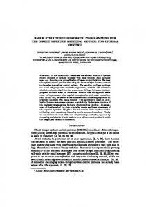
Fig. 2 Boundary of all „a , b… pairs satisfying inequality „4… and „5… for example „1…. The a, b pair for which ab is minimum is marked by „Œ….
共a共兲 , b共兲兲, for each 僆 兵其 having a solution in steps 共2兲 and 共3兲, which form the boundary of the allowed 共a , b兲’s. Some remarks regarding the topology of the 共a , b兲 region can be found in Ref. 关12兴. A QFT optimal controller is a controller for which the HFG is minimum 共see Horowitz and Sidi 关14兴兲. For C共s兲 = a共1 + bs兲 the optimal controller is the one for which ab is minimum. The following lemma states that this optimal controller lies on the boundary of the 共a , b兲 region or is as close to the boundary for the accuracy associated with the frequency grid searched and plant grid searched, given the assumption that P1 and P2 are uncertain. It is therefore sufficient to calculate the boundary of the 共a , b兲 region to find the optimal controller. Lemma 3.1 Let 共a , b兲 denote the set of all controllers solving the problem defined by equations 共3兲 and 共4兲. Suppose this set is not empty and denote by d the infimum of all the multiplications ab’s within the allowed 共a , b兲’s. Then there exists an a0, b0 pair on the boundary of the allowed 共a , b兲’s such that a0b0 = d. Proof. Denote by a1, b1 a pair for which a1b1 is infimum over all allowed 共a , b兲’s 共such finite infimum exists because closed loop stability requires lower bound on a and b兲. If a1, b1 is not on the boundary, then 共5兲 is an inequality, thus, there exists a0 = a1 − ⑀ such that for a0, b1 共5兲 is valid and the system is stable, which contradicts the assumption that a1b1 is infimum. Therefore, a1, b1 must be on the boundary. 䊏 Example 1: Design of a PD Controller. The plant pair P1, P2 as defined in Eq. 共3兲 and the sensitivity upper bound, M, are P1 =
M=
冏
1 −sT e , s2
T = 0.005 s,
P2 = sP1 ,
冏
2s3 , 共s + 10兲2共s + 30兲
s = j .
The open-loop transfer function is L = P1G where G = a共1 + bs兲 is a PD controller. The boundary of the 共a , b兲’s is given in Fig. 2, calculated for 300 frequencies, between = 1 and 700 rad/s. In this and the following examples, frequencies are chosen such that the plant does not change by more than 1 deg and 0.2 dB兲. From inequality 共5兲 for each frequency, , the boundary of the domain where L共j兲 must lie can be calculated. It is possible to 474 / Vol. 127, SEPTEMBER 2005
Fig. 3 Several QFT bounds satisfying inequality „4… and the open-loop transfer function L„s… for the pair a, b for which ab is minimum
draw these boundaries, known as QFT bounds. Figure 3 shows several such boundaries and the open-loop transfer function L共s兲 = P共s兲G共s兲, where G共s兲 = a共1 + bs兲 = 820共1 + 0.0348s兲 is the controller for which the HFG is minimum.
4 Automatic Loop Shaping of More Than TwoParameter Controllers An open-loop transfer function of the two-parameter controller can be written in the form L共s兲 = aP1共s兲共1 + bP2共s兲/P1共s兲兲. Let P denote a plant and choose P1 = PH and P2 / P1 = W, which gives the open-loop transfer function L = PG where the controller is G = aH共1 + bW兲. This observation is the basis for extending the method for the design of a controller of arbitrary structure. For example, consider the design of a lead or lag controller G共s兲 =
a共1 + bs兲 . 1 + s/c
The following algorithm can be used to find suitable 共a , b , c兲 triplets and the triplet whose HFG is the lowest. 共1兲 Fix the pole c. This will reduce the problem of searching the boundary of 共a , b兲 to a two-parameter controller given in Sec. 3. 共2兲 Find the 共a , b兲 boundary and save the best a, b pairs. If the criterion is lowest HFG, it is the pair for which ab is minimum. 共3兲 Repeat steps 共l兲 and 共2兲 for a reasonable range of c values. 共A guideline for how to choose the range of c values is given in example 共2兲.兲 共4兲 From all chosen controllers choose the best one one. If the criterion is lowest HFG, it is the one for which abc is minimum. Remark 4.1 The extension of lemma 3.1 to a three parameter controller is straightforward. Since for each searched c the nearoptimal ac, bc pair is known, it is possible to directly select a global near-optimum solution from all calculated triplets 兵ac , bc , c其. The denser the grid of c, the closer the solution will be to the global optimum. Moreover, for many engineering systems it Transactions of the ASME
Fig. 4 Several QFT bounds satisfying inequality „4… at different frequencies and the open-loop transfer function for the optimal triplet a, b, c for which abc is minimum
is straightforward to choose a frequency grid such that the boundary of all ac, bc pairs is calculated for points that differ by less than a percent, and thus the optimal solution is close to the one taken from the calculated solutions. 4.1 Example 2: Design of a Gain and Lead or Lag Controller. The plant and sensitivity function are the same as of those of Example 1. The frequency where the optimal solution of Example 1 crosses ⫺180 deg below the 0 dB line is 290 rad/s 共that is, c → ⬁ in this example兲. For the pole c to be effective, it should therefore contribute at least 5 deg phase lag at 290 rad/s. Here, the search for the pole c was started at 2900 and its value was decreased by 10% each iteration until it was sufficiently small that no solution existed. The optimal controller, found to be G共s兲 =
768共1 + 0.0535s兲 , 1 + s/155
is shown in Fig. 4, together with several QFT bounds. In comparison to the PD controller of example 共1兲, it shows the same performance with much lower control effort 共i.e., the open-loop transfer function above 0 dB is the same, while at high frequencies it is much lower兲. The main question of this search-type algorithm relates to the computational burden. For this example, the algorithm took 0.17 s. on a 1.6 GHz laptop using MATLAB® v.6.5 where the routine which solves the fourth-order Eq. 共8兲 was written efficiently in C. 4.2 Example 3: Design of a Gain Notch and Lead or Lag Controller. Many mechanical servo applications can be modeled as a load on a motor shaft. A classical model of such a system includes two integrators, a resonance, an anti-resonance whose frequency is lower than the resonant frequency, and a pure delay which may resemble a low-pass filter or a ZOH, that is, 1 s + 2d11s + · s2 s2 + 2d22s + 2
P共s兲 =
21 22
· e−sT .
A suitable controller for many applications of this type includes a lead element, a notch filter and a low-pass filter. The following example investigates a controller with a lead element and a notch filter. The addition of a low-pass filter could readily be included. The controller model is Journal of Dynamic Systems, Measurement, and Control
Fig. 5 Several QFT bounds satisfying inequality „4… and the open-loop transfer function for which the controller HFG is minimum „nominal plant is the one with the largest resonance frequency, here 105 rad/s…
G共s兲 =
冋
a共1 + bs兲 1 + s/c
册冋
1 + 2d33/s + 23/s2 1 + 2d43/s + 23/s2
册
.
Consider the problem of finding the lowest HFG controller, G共s兲, that stabilizes the uncertain plant, P共s兲, whose parameters are: d1 = 0.01, d2 = 0.03, the resonance-antiresonance pair is uncertain being one of the following: 1 = 50 rad/ s, 2 = 90 rad/ s or 1 = 55 rad/ s, 2 = 95 rad/ s, or 1 = 60 rad/ s, 2 = 100 rad/ s, or 1 = 65 rad/ s, 2 = 105 rad/ s and the delay T is 0.005 s or lower. The closed-loop sensitivity performance is defined by M共兲 =
冏
冏
2s3 , 共s + 10兲2共s + 10兲
s = j .
The following design algorithm was applied. 共1兲 Since a suitable notch filter should notch around the resonance, choose one of the following filters. 共a兲 d4 = 0.5 and d3 a value between 0.07 and 0.3, with seven equally spaced values in logarithmic scale. 共b兲 A value of 3 between the lowest resonance, 90 rad/s and 1.5 times the highest resonance, 105 rad/s, with eight values equally spaced in logarithmic scale. 共2兲 The pole, c, of the low-pass filter is chosen. Starting with a very large value of c, find where the open-loop transfer function crosses ⫺180 deg below the 0 dB line, say at c⬁. Search from a maximum value of c = 10c⬁ and decrease by 10% in each iteration until no solution exists. 共3兲 Search for the boundary of the 共a , b兲 domain and from it select the controller considered the optimal one. 共4兲 Repeat the previous steps for all chosen notch filters and low-pass filters. Save the optimal solution共s兲 for each iteration. 共5兲 From all saved optimal solutions choose a global optimal one. Implementing this algorithm gave the following controller G共s兲 =
冋
918共1 + 0.0774s兲 1 + s/136
册冋
册
1 + 2 · 0.224 · 95/s + 952/s2 . 1 + 2 · 0.5 · 95/s + 952/s2
Figure 5 presents the open-loop transfer function where the nominal plant P0 is the one with the lowest resonance frequency 共90 rad/s兲. It also includes several QFT bounds. The computational cost 共using a 1.6 GHz laptop and Matlab兲 associated with this four element controller was 35 s. SEPTEMBER 2005, Vol. 127 / 475
Fig. 7 A SISO two degree-of-freedom feedback system
y = Pu u = Fr − GHy, where P is a LTI plant known to belong to a set 兵P其, G is an LTI controller, r is the reference input, F is the prefilter, and H is the sensor. The QFT two degree-of-freedom problem can be phrased in two ways. Fig. 6 Several QFT bounds satisfying inequality „4… and the system’s open-loop transfer function „for k = 1… for which the controller HFG is minimum
4.3 Example 4: Design of a PID Controller With Filtered D. More than 90% of industrial feedback controllers are PI, PD, or PID with a low-pass filter on the D-term 关15,16兴, that is, the controller structure is of the following form: k Ds kI , G共s兲 = + k P + s 1 + s/c with the four design parameters 共kI , k P , kD , c兲. For this example, the uncertain plant and performance are P=
k −sT e , s2 + s
T = 0.005 s,
冏
gain uncertainty k 僆 关1,2兴
冏
2s3 M= , 共s + 10兲2共s + 30兲
s = j .
The design process is as follows. First, a PID controller is designed and the frequency where the optimal solution crosses ⫺180 deg below 0 dB is calculated. 共This occurs at 290 rad/s.兲 The expected pole on the D term should therefore be around that value. A search for the pole in the frequency range 关70, 2900兴 was conducted. Searching over forty c values equally spaced logarithmically suffices since successive c values then differ by less than 10%. The optimal controller was found to be G共s兲 =
27.2 1530 + 506 + s 1 + s/387
The open-loop transfer function for the plant where k = 1 is shown in Fig. 6 together with some QFT bounds. This figure verifies graphically both stability and satisfaction of the specifications. An important question is what conditions must exist for a successful application of the algorithm proposed here. A key condition is that there is a fixed controller G0共s兲 such that 共a + bs兲G0共s兲 is a solution to the problem for some a, b values, or, more generally, there are fixed controllers, G1 and G2, such that aG1 + bG2 is a solution to the problem for some a, b values. Furthermore, it is assumed that the designer has some idea of the controller structure appropriate for the problem.
共1兲 Given a function A共兲, design F and G such that
冏
冏
P共j兲G共j兲F共j兲 − F共j兲 艋 A共兲, 1 + P共j兲G共j兲
Consider the feedback system depicted schematically in Fig. 7 and described by the equations 476 / Vol. 127, SEPTEMBER 2005
P 僆 兵P其.
共2兲 Given two functions A共兲 and B共兲, design F and G such that A共兲 艋
冏
冏
P共j兲G共j兲F共j兲 艋 B共兲, 1 + P共j兲G共j兲
for all
P 僆 兵P其.
The first problem, assuming F is given, is analogous to the ALS problem defined in Sec. 3 because it is equivalent to
冏
冊
1 A共兲 艋 , 1 + P共j兲G共j兲 兩F共j兩
P 僆 兵P其.
for all
The second problem, where F is assumed known, is also analogous to this problem based on the following lemma. Lemma 5.1 Let M ⫽ 1 be a constant. A complex number L satisfies the inequality
冏 冏
L 艋M 1+L
if and only if it satisfies the inequality
冏
冏
冏
1 艋 M, 1 + L/M 0
冏
1 艌 M, 1 + L/M 0
if
if
M⬎1
M ⬍ 1;
M0
M2 . M2 − 1
Proof. Substitute L = x + jy in both inequalities and after manipulation it can be shown that both are the same inequality. 䊏 Note that a bound for M = 1 can always be calculated by replacing it by a value very close to 1. Based on lemma 5.1 a design process for the second two degree-of-freedom problem, suited for the design of a two-parameter controller, is 共1兲 Choose the prefilter F, the problem will then be analogous to designing G such that M1 =
5 The Design of Two DOF Systems by Reduction to One DOF Systems
for all
冏
冏
A共兲 B共兲 P共j兲G共j兲 艋 艋 = M 2, 兩F共j兲兩 1 + P共j兲G共j兲 兩F共j兲兩 for all
P 僆 兵P其.
共9兲
共2兲 Find the boundary of the 共a , b兲’s solving the right side of inequality 共9兲 Transactions of the ASME
冏
冏
1 艋 M 1, 1 + P共j兲G共j兲/M 0
for all
P 僆 兵P其
where M 0 = M 21 / 共M 21 − 1兲, change the inequality if M 1 ⬍ 1 according to lemma 5.1. 共3兲 Find the boundary of the 共a , b兲’s solving the left side of inequality 共9兲
冏
冏
1 艌 M 2, 1 + P共j兲G共j兲/M 0
for all
P 僆 兵P其
where M 0 = M 22 / 共M 22 − 1兲, change the inequality if M 1 ⬍ 2 according to lemma 5.1. 共4兲 The intersection of the closure of the latter two domains is all 共a , b兲 pairs being sought. Pick an optimal a, b pair as a solution. The extension to controllers involving more than two parameters is as described in Sec. 4.
6
Conclusions
The paper presents a noniterative based algorithm to design structured controllers satisfying frequency-dependent sensitivity specifications. Assuming that the designer has some idea of the controller structure and a suitable range of its parameters, the proposed approach can be used to find the boundary of the set of possible solutions. Internal points are of no interest if the QFT optimal criterion is used. Being noniterative, the algorithm is efficient and fast, and offers several additional attractive properties. It can be applied to unstructured uncertain plants, be they stable, unstable or nonminimum phase. It can be used to design a near optimal controller of a given structure for plants which are typically difficult to control, such as highly underdamped plants. The algorithm can be used to sort controller designs based on a given criterion, such as the one with the lowest high-frequency gain. The technique can be extended to incorporate notch filters and low-pass filters into the controller. In addition, hard restrictions can be included, such as bounding the damping factor of a notch filter or adding a low-pass filter with a given cutoff frequency in order to limit the sensor noise effect.
Journal of Dynamic Systems, Measurement, and Control
References 关1兴 Gera, A., and Horowitz, I., 1980, “Optimization of the Loop Transfer Function,” Int. J. Control 31, pp. 389–398. 关2兴 Ballance, D. J., and Gawthrop, P. J., 1991, “Control System Design Via a Quantitative Feedback Approach,”Proceedings of the IEE Conference Control91, Heriot-Watt University, Edinburgh UK, Vol. 1, pp. 476–480. 关3兴 Chait, Y., Chen, Q., and Hollot, C. V., 1999, “Automatic Loop-Shaping of QFT Controllers Via Linear Programing,” ASME J. Dyn. Syst., Meas., Control, 121, pp. 351–357. 关4兴 Thompson, D. F., and Nwokah, O. D. I., 1994, “Analytic Loop Shaping Methods in Quantitative Feedback Theory,” ASME J. Dyn. Syst., Meas., Control 116, pp. 169–177. 关5兴 Thompson, D. F., 1998, “Gain-Bandwidth Optimal Design for the New Formulation Quantitative Feedback Theory,” ASME J. Dyn. Syst., Meas., Control 120, pp. 401–404. 关6兴 Garcia-Sanz, M., and Guillen, J. C., 2000, “Automatic Loop Shaping of QFT Controllers Via Genetic Algorithm,” Proceedings of the 3rd IFAC Symposium on Robust Control Design (RO-COND 2000), Kidlington, UK, Elsevier Science, New York, Vol. 2, pp. 603–608. 关7兴 Zolotas, A. C., and Halikias, G. D., 1999, “Optimal Design of PID Controllers Using the QFT Method,” IEE Proc.: Control Theory Appl. 146共6兲, pp. 585– 589. 关8兴 Besson, V., and Shenton, A. T., 2000, “Interactive Parameter Space Design for Robust Performance of MISO Control Systems,” IEEE Trans. Autom. Control, 45共10兲, pp. 1917–1924. 关9兴 Fransson, C. M., Lennartson, B., Wik, T., Holmstrom, K., Saunders, M., and Gutman, P. O., 2002, “Global Controller Optimization Using Horowitz Bounds.” IFAC World Congress, Barcelona, Spain, 21–26 July 2002. 关10兴 Yaniv, O., 1999, Quantitative Feedback Design of Linear and Nonlinear Control Systems, Kluwer Academic, Dordrecht. 关11兴 Yaniv, O., and Nagurka, M., 2003, “Robust PI Controller Design Satisfying Sensitivity and Uncertainty Specifications,” IEEE Trans. Autom. Control 48共11兲, pp. 2069–2072. 关12兴 Yaniv, O., and Nagurka, M., 2004, “Design of PID Controllers Satisfying Gain Margin and Sensitivity Constraints on a Set of Plants,” Automatica 40共1兲 pp. 111–116. 关13兴 Panagopoulos, H., Astrom, K. J., and Hagglund, T., 1998, “Design of PI Controllers Based on Non-convex Optimization,” Automatica 34共5兲, pp. 585–601. 关14兴 Horowitz, I. M., and Sidi, M., 1972, “Synthesis of Feedback Systems with Large Plant Ignorance for Prescribed Time Domain Tolerances,” Int. J. Control 16共2兲, pp. 287–3098. 关15兴 Astrom, K. J., and Hagglund, T., 2001, “The Future of PID Control,” Control Eng. Pract., 9, pp. 1163–1175. 关16兴 Ho, W. K., Lee, T. H., Han, H. P., and Hong, Y., 2001, “Self Tuning IMC-PID Control with Interval Gain and Phase Margin Assignment,” IEEE Trans. Control Syst. Technol. 9共3兲, pp. 535–541.
SEPTEMBER 2005, Vol. 127 / 477