computacional para modelagem simbólica de sistemas dinâmicos. Os recursos implementados são ilustrados através da resolução de problemas-exemplos.
AUTOMATIC MODELLING OF LUMPED PARAMETERS DYNAMIC SYSTEMS Alberto Adade Filho and João Bosco Gonçalves Instituto Tecnológico de Aeronáutica (CTA-ITA-IEMP) (Technological Institute of Aeronautics) 12228-900 - S. José dos Campos - SP - Brazil
ABSTRACT: This paper describes the framework and the approach that are utilized in the implementation of a software for automated mathematical modelling of dynamic systems. Application examples illustrate the main features and possibilities of this software. The formalism utilizes a system linear graph representation associated to a systematic procedure in order to obtain a state-space model of lumpedparameters systems. This mathematical modelling method is automated using modern computational symbolic processing capabilities. RESUMO: Este trabalho descreve a base formal e a abordagem utilizada para a implementação de um ambiente computacional para modelagem simbólica de sistemas dinâmicos. Os recursos implementados são ilustrados através da resolução de problemas-exemplos. O formalismo se aplica a sistemas a parâmetros concentrados e utiliza a representação tipo grafo de sistemas associada a um procedimento sistemático para obter um modelo matemático do sistema no espaço de estados. A automatização do processo de modelagem explora os recursos computacionais modernos de processamento simbólico.
1
INTRODUCTION
Mathematical modelling can become an essential part in the process of analyzing a dynamic system, as a mean to make predictions, to optimize performance or to perform qualitative evaluations about the system. In addition, models expressed in symbolic form allow the derivation of alternative models appropriate to the objectives of the analysis; for example, modelling for purpose of control system design. There are several computer programs available to support dynamic systems analysis and simulations studies; for example, Felez et al., 1990, which utilizes a bond graph approach; Andrews, 1971, which utilizes a vector network approach. However, computer programs designed to derive mathematical models, i.e. models in symbolic form, are scarce. The system graph representation associated with a systematic procedure for obtaining state-space equations provides an interesting alternative to automate the process of mathematical modeling of lumped parameters systems, making use of the available modern computational symbolic processing Artigo submetido em 18/11/97 1a. Revisão em 26/02/98; 2a. Revisão em 03/06/98; Aceito sob recomendação do Ed. Cons. Prof.Dr. Liu Hsu
resources. Automated modelling provides greater reliability on the derived models, reduces the time and effort to obtain them and in general, results in more efficient analysis studies. In the next two sections we present a theoretical-computational formalism to derive a symbolic state-space model for lumpedparameters dynamic systems. A section dedicated to examples is provided to highlight the main features of the developed software.
2 2.1
SYSTEM REPRESENTATION AND THEORETICAL ASPECTS Models Comprised In This Analysis
In this paper, we treat lumped-parameter dynamic systems and we consider two classes of systems: linear time-variant systems having two-terminal RLC (resistance-inductance-capacitance) generalized elements, mutual inductances and four-terminal generalized transformer elements; and non-linear timeinvariant systems, having two-terminal RLC generalized elements. In both cases the systems may contain independent generalized voltage and current sources (external inputs). A large family of plants is considered, especially those constituted by the interconnection of mechanical, electrical, electro-mechanical, hydraulic and electro-hydraulic components. Seeking generalization and consistency, it was necessary to impose some hypotheses; in the linear case, they were kept to a minimum in order not to burden the user or to restrain unnecessarily the practical applications of the developed software. In the nonlinear case, they are listed in the section 2.4.2.
2.2
System Graph Representation
In the System Graph (or Linear Graph) representation (Shearer et alii, 1969), a set of connected branches, representing the lumped elements of the system, forms a graph describing the real system or its physical model. The generalization of the Kirchhoff laws to electrical circuits can be utilized to impose the graph the constraints to flows and loops (continuity and compatibility conditions). The dynamic equations of the system, i.e. its mathematical model, can be obtained by adding to the constraint equations set, the equations which describe the system elements. The mobility analogy (Firestone, 1933) among electrical circuits and the other types of systems,
SBA Controle & Automação Vol. 10 no. 01 / Jan., Fev., Mar, Abril de 1999
1
mechanical, thermal and/or fluid, can be utilized in order to deal with all of them in a generalized way. So, the problem is to exploit the system graph approach for representing generalized lumped-parameters dynamic systems and a systematic procedure for defining state variables and relate them, in order to implement an integrated software that automates the modelling process for obtaining the state-space equations in a symbolic form as well as its numerical simulation. By making use of quantities like the incidence matrix of the system graph, its normal tree, fundamental cutsets and loops, defined in the section 2.3, it is possible to deduce a general state-space model in terms of special matrices representing the elements of the system and the way they are connected (Kuh and Roher, 1965; Adade Fo, 1992; Gonçalves, 1995). Several algorithms were developed (Gonçalves, 1995) to extract information from the system graph and to implement the systematic procedure for modelling (as commented in the section 3).
set of state variables, since steps (a) and (b) guarantee a nonredundant choice of these variables.Also, from the computational point of view, steps (c) and (d) are represented in the calculation of the matrices presented in the next section. This systematic procedure is suggested in some texts like (Kuh and Roher, 1965; Wellstead, 1979; Chen, 1984).
2.4 2.4.1
System Equations For Automated Modelling Linear systems
The algebraic manipulation utilizing the systematic procedure to deduce a linear state-space model, x� (t ) = A(t )x(t )+ B(t )u (t )
(1)
is extensive and can be found in details in Gonçalves (1995). In this sub-section it is presented the final form of the models considering two different sets of state-variables. Consider, - the vector of independent sources:
2.3
[
Systematic Procedure For Modelling In The State-Space
A systematic procedure, as described in the sequel, allows us to derive relationships among the variables, needed to automate the process of obtaining state-space models from the system graph representation: a - define a normal tree. This tree is built from the oriented graph of the system, adopting the following sequence for choosing the tree branches: all “across” variable sources, the maximum number of passive elements type-A (generalized capacitors), type-D (generalized dissipators) and a minimum number of type-T (generalized inductors) passive elements; in the end of this process, the elements not included in the normal tree will be included in the complementary graph, called cotree. Every branch not in the tree is called a link. b - Choose as state variables: b1 - the “across” variables of the type-A (generalized capacitors) elements inserted in the normal tree (vC) and the “through” variables of the type-T (generalized inductors) in the co-tree (iL); or, alternatively,
u (t ) = j T e T
d - Apply node law to the fundamental cutsets or the loop law to the fundamental loops, of every branch that contributes with a state variable.
(2)
j(nra,1) → vector of "through" variables sources, the k-th element being the algebraic sum of the "through" variables sources belonging to the k-th fundamental cutset. e(nb,1) → vector of "across" variables sources, the i-th element being the algebraic sum of the "across" variables sources belonging to the i-th fundamental loop. Partitioning the vector of independent sources in accordance to the type of the elements, using the notation for subscripts, C : capacitors in the normal tree; S : capacitors in the co-tree; L : inductors in the co-tree; Γ : inductances in the normal tree; R : resistors in the co-tree; G: conductances in the normal tree; θ : transformer port in the normal tree; α : transformer port in the co-tree, we obtain, 0 j [ j ]= C jG jΓ
eS e and [e]= R eL 0
(3)
The fundamental loops and cutsets equations can be written as: v1 0 = T i 2 F
− F i1 e + 0 v2 j
(4)
where the vectors v2 and v1 (i2 and i1) denote the across (through) variables of the passive elements inserted in the normal tree (cotree), respectively. This matrix F is called the fundamental loop matrix and its transpose is equal to the fundamental cutset matrix. Partitioning F in accordance to the systematic procedure to choose the normal tree (see the Symbol List to a comment about each sub-matrix):
It should be pointed out that the application of this systematic procedure allows to describe the system utilizing a minimum 2
T
where:
b2 - the integrated “through” variables of the type-A elements inserted in the normal tree (qC) and the integrated “across” variables of the type-T elements in the co-tree (ϕL). c - Write each (across and/or through) variable of all type-D and type-A elements in the co-tree, and of the type-T elements inserted in the normal tree, as well as the generalized transformers energy ports as functions of the state variables, applying the loop law to the fundamental loops and the node law to the fundamental cutsets, formed by those branches. A fundamental loop is a unique loop formed by every link and some tree branches; a fundamental cutset is a unique cutset formed by every tree branch with some links.
]
SBA Controle & Automação Vol. 10 no. 01 / Jan., Fev., Mar, Abril de 1999
0 F F = Rθ FLθ Fαθ
FSC FRC FLC FαC
0 0 FLΓ 0
0 FRG FLG FαG
(
T9 = FαG T N 21 I I θ − Fαθ T N 21 (5)
( (I
F T N I − F T N 21 I θ 21 αθ αG G1 FRθ N 12
Vα
)
−1
)F )F
+ Fαθ T N 12
FRθ T G1 FRC +
−1
Rθ
T
+ FRG T
(18)
−1
αC
Utilizing the equations describing the generalized RLC and transformers elements, as well as the constraints equations from the oriented system graph, the following matrices can be defined (also see Symbol List):
T10 = FαG T N 21 I I θ − Fαθ T N 21
(
)
FLθ T
(19)
- the capacitive matrix of the system:
T11 = FαG T N 21 I I θ − Fαθ T N 21
(
)
FRθ T
(20)
C = C 2 + FSC T C1 FSC
(6)
- the inductive matrix of the system: L = L11 + FLΓ L21 + L12 FLΓ T + FLΓ L22 FLΓ T
(7)
T
(8)
G = G2 + FRG T G1 FRG
(9)
- the matrices related to the energy ports of the generalized transformers:
(
)
FRθ
)
FLθ T
T1 = FαC N 21 I I θ − Fαθ N 21 T
(
T2 = FαC T N 21 I I θ − Fαθ T N 21
−1
−1
T
(10)
(11)
T3 = FLθ N12 (I Vα + Fαθ N12 ) FαC
(12)
T4 = FLθ N 12 (I Vα + Fαθ N12 )−1 FαG
(13)
−1
− [ FRθ N12 (I Vα + Fαθ N 12 )−1 FαG R2 FαG T −
(
− FRG R2 FαG ] N 21 I Iθ − Fαθ N 21 T
1
In addition, consider,
(
)
(
)(
)
)
−1
T [FRθ N12 IVα +Fαθ N12 FαG R2 FαG − −1 T T FRG R2 FαG ] N21 I Iθ −Fαθ N21 FLθ
)
T7 = FRθ N 12 (I Vα + Fαθ N 12 )− FαC R2
(
T8 = FαG N 21 I Iθ − Fαθ N 21 T
( (I
T
F T N I − F T N 21 αG 21 Iθ αθ G1 FRθ N12
Vα
1
(
(
(
)
)
)
(23) (24) (25)
To write the state-space equations in the standard form, the state variables vector, as chosen in the step b1 of the systematic procedure, is redefined as:
v −C −1 F T SC C1 eS x = C −1 iL + L (L12 + FLΓ L22 ) jΓ
C A(t ) = 0
−1
C −1 B(t ) = 0
(15)
(26)
• y − C 0 L−1 k 0 I B1 L−1 0 B4
• z − L B11 B 2 B3 B5 B12 B6 h
(27)
0 I
(28)
where,
(16)
FRθ G1 FRG −
(
)
B1 = FRC T + T1 (R +T5 )− (T7 − FRG R2 )
(29)
B11 = −h L−1 (L12 + FLΓ L22 )
(30)
1
T
)F )F
+ Fαθ N12 T
)
1
z = (T4 − FLG )(G + T8 )− T10 + FLG T
(14)
1
−1
)
1
FRθ
−1
(
1
k = (T3 − FLC )+ (T4 − FLG )(G + T8 )− T9 − FRG T G1 FRC
T T6 = FRθ N12(IVα + Fαθ N12 )−1 FαG R2 FLG +
(
(21)
In this case, the matrices A(t) e B(t) of the state-space model are given by:
T5 = FRθ N12 (I Vα + Fαθ N12 )−1 FαG R2 FRG T − T
T12 = FRθ N 12 (I Vα + Fαθ N 12 )− FαC
h = FLC T + T2 + FRC T + T1 (R + T5 )− T6 − FRG R2 FLG T
- the conductive matrix of the system:
T
−1
y = FRC T + T1 (R +T5 )− (T12 − FRC )
- the resistive matrix of the system: R = R1 + FRG R2 FRG
−1
−1
Rθ
T
−1
αG
T + FRG
B 2 = yC (17)
(
−1
F SC T C 1
)
(31)
B3 = FRC T + T1 (R + T5 )− B 4 = (T4 − FLG )(G + T8 )−
1
1
B5 = − z L−1 (L12 + FLΓ L22 )
(32) (33) (34)
SBA Controle & Automação Vol. 10 no. 01 / Jan., Fev., Mar, Abril de 1999
3
B12 = k C −1 FSC T C1
(35)
(
)
B6 = (T4 − FLG )(G +T8 )−1 FRG T +T11 G1
(36)
For the same reason, that is, to write the state-space equations in the standard representation (without explicit derivatives of the input), the vector of state variables, as chosen in the step b2 of the systematic procedure, is redefined as:
qC − C2C −1 FSC T C1eS x(t ) = −1 ϕ L + L11 L (L12 + FLΓ L22 ) jΓ
If equation (42) can be solved for i as a function of φ, i = I(φ), the element is said to be integrated "across" variable controlled; on the contrary, if this equation can be solved for φ as a function of i, φ = Φ(i), the element is said to be "through" variable controlled. The constitutive relationship of a type-D element can be represented by a curve in the v-i plane, the equation being: (43) fR(v,i) = 0
(37)
If equation (43) can be written as v = V(i), the element is said to be "through" variable controlled; on the contrary, if i = I(v), the element is said to be "across" variable controlled.
In this case, the matrices A(t) e B(t) of the state-space model are given by:
Equations (41)-(43) make possible to deduce a dynamic model in the sate-space,
−1 d yC − CC2−1 C −1C2 0 2 dt A(t ) = L−1L11 0 kC2−1
(
)
C −1C 2 B (t ) = 0
B11
B2
B3
B5
B12
B6
2.4.2
0 I B1 −1 L L11 0 B4
d −1 zL11 − LL11 dt hL11−1
(
)
0 I
H1 - the system is time-invariant; (39) H2 - there are no two-ports (four terminals) elements; H3 - the non-linear generalized RLC elements can be described by parametric equations;
This section presents the formulation of a dynamic model to systems which have non-linear RLC generalized elements. Utilizing matrices conveniently chosen, this formulation allows an automatization of the modelling process through the use of symbolic manipulation software. Only nonlinear generalized elements whose characteristics can be represented by parametric equations are considered. Conditions to the existence of a state-space model are presented in terms of the topological constraints and the characteristics of the elements, allowing, by inspection of the system graph, to check the existence of the required model. This section is based on (Brayton and Moser, 1964; Chua and Roher, 1965; Desoer and Katzenelson, 1965; Stern, 1966). Lets define a parametric equation as a subset C in the Euclidean plane E2,
}
C= (w, z)∈E2 :w = w(ξ ), z = z(ξ )eξ ∈[a, b] (40) such that w e z are continuous functions of the parameter ξ, being differentiable within the interval of interest. With this definition it is possible to characterize the nonlinear RLC generalized elements as follows. The constitutive relationship to a nonlinear type-A element can be represented by a curve in the q-v plane, being q the integrated "through" variable and v the "across" variable of the element, which equation is: (41) fC(v,q) = 0 If equation (41) can be solved for v as a function of q, v = V(q), the element is said to be integrated "through" variable controlled; on the other hand, if his equation can be solved for q as a function of v, q = Q(v), the element is said to be "across" variable controlled. Similarly, the characteristics of a nonlinear type-T element can be represented by a curve in the φ-i plane, being φ the integrated "across" variable and i the "through" variable, which equation is: fL(φ,i) = 0 4
(44)
In addition, it is assumed the following hypotheses:
Nonlinear systems
{
x� = f (x, u )
(38)
(42)
H4 - there are no fundamental loops formed by type-D elements; H5 - all type-D elements in the co-tree are “across” variables controlled; H6 - all type-D elements in the normal tree are “through” variables controlled; H7 - the type-A elements are "across" variables controlled; H8 - the type-T elements are “through” variables controlled. Hypotheses H4-H6 allow us to express, in a direct way, the variables of type-D elements in terms of the adopted state variables; otherwise, we should define inverse functions for the characteristics of the elements (Desoer and Katzenelson, 1965). Hypotheses H7-H8 allow us to derive, in a direct way, a dynamic model in terms of the "across" variables of the type-A elements in the normal tree and "through" variables of type-T elements in the co-tree. In accordance to the hypotheses H1-H8 the equations for the generalized RLC elements can be written using explicit functions, iS C1 0 d v S i = C 0 C 2 dt vC
(45)
for the generalized capacitors;
(
T vG = R2 $ FLG i L + jG
)
i R = G1 $ (− FRC vC + e R )
(46)
for the generalized resistors; and v L L11 = vΓ L21
L12 d i L L22 dt iΓ
(47)
for the generalized inductors. The submatrices in the equations (45) and (47) are determined by:
SBA Controle & Automação Vol. 10 no. 01 / Jan., Fev., Mar, Abril de 1999
∂ [QS $ (− FSC vC + eS )] ∂ vC ∂ [QC (vC )] C2 = ∂ vC C1 =
(48)
•
(49)
)
(50)
(
)
(51)
(
)
(52)
(
)
(53)
∂ L12 = Φ 11 (i L ,iΓ ) $ FLTΓ i L + j Γ ∂ iΓ ∂ L21 = Φ 22 (i L ,iΓ ) $ FLTΓ i L + jΓ i ∂ L
∂ L22 = Φ 22 (i L ,iΓ ) $ FLTΓ i L + jΓ ∂ iΓ
•
T T T CC2 qC = FRC G1$[−FRCVC (qC )+ eR ]+ FLC I L (φL ) + jC + FSC C1eS
[
•
]
•
T LL11φL = − FLCVC (qC )− FLG R2 $ FLG IL (φL )+ jG − FLΓ L22 jΓ −eL
(
∂ L11 = Φ11 (i L ,iΓ ) $ FLTΓ i L + j Γ ∂ iL
Utilizing hypotheses H9-H12, we obtain the following dynamic model:
The algebraic manipulation to derive state-space models is similar to the linear case and can be found in details in Gonçalves (1995). The results are presented in the sequel for two different sets of state variables. For the first set, vC e iL, the dynamic model is given by: T T C vC = F T RC G1 $ (−FRC vC + eR )+ jC + FLC iL +FSC C1 eS •
(59)
where,
∂ {QS $ [− FSC VC (q C )+ ∂ vC d [VC (qC )] C2 = d qC d [I L (φ L )] L11 = dφ L ∂ Φ 22 $ FLTΓ I L (φ L )+ j Γ L22 = ∂ φL
e S ]}
C1 =
{
The symbol (°) in these equations denotes function of function. In case hypothesis H4 is not verified (this condition is analysed by the implemented software, which provides a warning message in case of its violation), we can introduce to the original system graph, a linear capacitor in parallel to the typeD elements of the co-tree that are forming the respective fundamental loops; a linear capacitor inserted in the system graph allows to simulate a residual parasitic capacitance, which is a characteristic of physical systems. Alternatively, we can insert linear inductors in series to type-D elements in the normal tree, that are forming the respective fundamental loops; a linear inductor inserted this way allow us to simulate parasitic inductance, which is a characteristic of physical systems. It is assumed no mutual coupling for the linear inductances inserted in the original system graph.
(58)
3
[
(60) (61) (62)
]}
(63)
T C = FSC C1 FSC + C2 −1
(64)
L = L11−1 + FLΓ L22 FLTΓ
(65)
ASPECTS OF THE COMPUTER IMPLEMENTATION
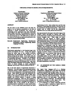
The automatic modelling software (called MASD, an acronym for “Modelagem Automática de Sistemas Dinâmicos”) is constituted by Turbo Pascal routines which implement the user interface program (problem definition) and the system graph characterization, as well as a program written in Mathematica to manipulate and obtain the state-space symbolic form equations. MASD main features are illustrated in this paper through application examples. A flow diagram of MASD is shown in figure 1. In this diagram, system definition refers to the user input of data describing the system graph topology (number of nodes, number of branches, initial and final node numbers for each branch element), the type of elements of the system and the simulation parameters. This numerical data input is done in a
•
LiL = −FLC vC − FLG R2 $ (F i + jG )− (L12 +FLΓ L22 ) jΓ + eL •
(54)
Start
T LG L
(55) System Definition
where, T C = FSC C1 FSC + C 2
L=
L11 + FLΓ L21 + L12 FLTΓ
1
•
(56) + FLΓ L22 FLTΓ
(57)
To derive a dynamic model for the second set of state variables, qC e φL, lets consider hypotheses H9-H12 in substitution of hypotheses H7-H8 as below: H9 - the type-A elements in the normal tree are of controlled “through” variables; H10 - the type-T elements in the co-tree are of controlled integrated "across" variables; H11 - the type-A elements in the co-tree are of controlled "across" variables; H12 - the type-T elements in the normal tree are of controlled “through” variables;
Form the Incidence Matrix Choose Normal Tree
Fundamental Loop Matrix Determination
Save Files with Extension “.mat”
Symbolic Modelling and Simulation
MASD Output Information
1 Figure 1 – MASD Program Flow Diagram
SBA Controle & Automação Vol. 10 no. 01 / Jan., Fev., Mar, Abril de 1999
5
questions and answers session, controlled by the user interface routine. The dialog boxes for data input are presented in the Appendix. Concluded the data input, the information about the graph topology are then reorganized by MASD in a matrix form through an incidence matrix, which is the base for the systematic classification of tree branches and links, in the process of defining a normal tree and its respective co-tree. Tree search algorithms are utilized in this process as well as to obtain the fundamental loop matrix (Gonçalves, 1995).
K1 = 1.8 [N/m]
K2 = 1.8 [N/m]
K3 = 1.5 [N/m] n1 = ra = 0.1 [m] n2 = 2 cos(α) n3 = rb = 0.1[m] α = 0.524 [rad]
Once the fundamental loop matrix is obtained and adequately partitioned, the next step of the program is to save the required information (those matrices defined in the modelling equations, parameters of the elements, parameters of simulation etc) for the symbolic processing session; such information are saved as files .mat. The algebraic manipulation program to deduce the dynamic mathematical model, as well as its simulation, is part of MASD and implemented using the software Mathematica for Windows v2.1. In the flow diagram of figure 1 the dashed line indicates that the symbolic manipulation program must be activated by the user, inside Mathematica Other algorithms, as commented above, were implemented in Turbo Pascal v5.5. MASD computational program, for the linear case, provides as output the matrices A(t) e B(t) and the vectors x(t) and u(t); for the non-linear case it provides a model in accordance to eq.(45). In both cases, if required by the user, it provides a numerical simulation of the model.
4
APPLICATION EXAMPLES
4.1
Linear System
This example shows results obtained using MASD for modelling the mechanical system (Wellstead, 1979) represented in the figures 2 and 3.
Figure 2 - Mechanical System Assuming numerical simulation of the system is required, consider the following fictitious values for the lumped elements of this system M1 = 3 [kg]
M2 = 3 [kg]
Is1 = 1[Nm]
Is2 = 2 [Nm]
B1 = 1.9 [Ns/m] B2 = 1.2 [Ns/m]
Figure 3 - System Graph : After data input, which consists in defining the system graph as shown in the Fig.3, in a questions and answers session controled by the user interface program (see the Appendix), MASD represents internally the graph through an incidence matrix; also, utilizes an especific terminology in accordance to each type of element (Cg, Bg, Kg for generalized capacitance, resistance and inductance, respectively; Fe, Fa for the generalized across- and through-variable sources; Te, Ta for the transformer ports inserted in the normal tree and co-tree, respectively), and utilizes a numeric index for each element, depending on the order they are entered by the user. Five files are generated by MASD after data input, with information for the next phase of the symbolic modelling process. For example, MASD provides, in the file arq1.mat a description of the elements of the system, in this problem the capacitance matrix (C2), the resistance matrices (R1 e R2) and the inductance matrix (L11); also, the transformation ratio matrix (n12) as well as the external sources vector (Fa). In the file arq2.mat, MASD provides the sub-matrices of the fundamental loop matrix F (see eq. (5)): Arq1.mat C2 = {{Cg1,0},{0,Cg2}}; R1 = {{1/Bg1,0},{0,1/Bg4}}; R2 = {{1/Bg2,0},{0,1/Bg3}}; L11 = {{1/Kg1,0,0},{0,1/Kg2,0},{0,0,1/Kg3}}; n12 = {{1/n1,0,0},{0,1/n2,0},{0,0,1/n3}}; Fa = {{Fa1,0},{0,Fa2}}; Arq2.mat Fre = {{0,0,0},{0,0,0}}; Frc = {{-1,0},{0,-1}}; Frg = {{0,0},{0,0}}; Fle = {{0,0,0},{0,0,0},{0,1,0}}; Flc = {{0,0},{0,0},{0,0}}; Flg = {{-1,0},{0,-1},{0,0}};
B3 = 1.2 [Ns/m] B4 = 1.9 [Ns/m] 6
SBA Controle & Automação Vol. 10 no. 01 / Jan., Fev., Mar, Abril de 1999
Fae = {{0,0,0},{1,0,-1},{0,0,0}}; Fac = {{-1,0},{0,0},{0,-1}}; Fag = {{0,0},{1,1},{0,0}}; Fic = {{-1,0},{0,1}}; Fig = {{0,0},{0,0}};
x(t) = {{qc[1][t]},{qc[2][t]},{ fi[1][t]},{ fi[2][t]},{ fi[3][t]}} The input vector is: u(t) = {{-Fa1}, {Fa2}, {0}, {0}}
Also, at the end of the data input MASD generates the following information for the user:
At the end of the symbolic modelling process, the ij-elements of the system matrix A(t) were obtained by MASD as: a[1,1] = -(Bg1/Cg1),a[1,2]= 0, a[3,1] = 0, a[4,1] = 0, a[5,1] = -((Kg3*n1)/n2) a[2,1] = 0, a[2,2] = -(Bg4/Cg2), a[3,3] = 0, a[3,4] = 0, a[3,5] = (Kg3*n3)/n2 a[3,1] = 0, a[3,2] = 0, a[3,3] = -(Kg1/Bg2), a[3,4] = 0, a[3,5] = Kg3/(Bg2*n2) a[4,1] = 0, a[4,2] = 0, a[4,3] = 0, a[4,4] = -(Kg2/Bg3), a[4,5] = Kg3/(Bg3*n2) a[5,1] = n1/(Cg1*n2), a[5,2] = -(n3/(Cg2*n2)), a[5,3] = -(Kg1/(Bg2*n2)), a[5,4] = -(Kg2/(Bg3*n2)), a[5,5] = ((Bg2 + Bg3)*Kg3)/(Bg2*Bg3*n2^2)
TREE BRANCHES: Element Te1 Te2 Te3 Cg1 Cg2 Bg2 Bg3
initial node 3 5 8 2 9 3 7
final node 1 6 1 1 1 4 8
magnitude 0.1 2Cos[0.524] 0.1 3 3 1.2 1.2
LINKS (CO-TREE BRANCHES): element initial node final node Bg1 2 1 Bg4 9 1 Kg1 3 4 Kg2 7 8 Kg3 5 6 Fa1 2 1 Fa2 1 9 Ta1 1 2 Ta2 7 4 Ta3 1 9
magnitude 1.9 1.9 1.8 1.8 1.5 1 2 0.1 2Cos[0.524] 0.1
and the ij-elements of the matrix B(t) were obtained as: b[1,1] = 1, b[1,2] = 0, b[3,1] = 0, b[4,1] = 0 b[2,1] = 0, b[2,2] = 1, b[2,3] = 0, b[2,4]= 0 b[3,1] = 0, b[3,2] = 0, b[3,3] = Bg2^(-1), b[3,4] = 0 b[4,1] = 0, b[4,2] = 0, b[4,3] = 0, b[4,4] = Bg3^(-1) b[5,1] = 0, b[5,2] = 0, b[5,3] = 1/(Bg2*n2), b[5,4] = 1/(Bg3*n2)
4.2
A NONLINEAR SYSTEM
A hydraulic reservoir system is shown in figure 4 and its analogous circuit (Q-i) is shown in figure 5. This system, consisting of a large hilltop reservoir feeding two smaller town reservoirs, is described in Athans et alii (1974),
Choosing a standardized set of state variables we have that the state vector is composed by the integrated through-variable of the mechanical capacitance Cg1 and the integrated acrossvariables in the mechanical inductances kg1 and kg2, respectively:
where: hydraulic capacitance of the main reservoir
Cr F6 F5
h
A2
A1
Cr
C1 C2
C p2 R2
F4
Q2
Q1
C p1
R1
C v1
C v2
F3
Figure 4 - Hydraulic
Figure 5 - Analogous Circuit SBA Controle & Automação Vol. 10 no. 01 / Jan., Fev., Mar, Abril de 1999
7
Similarly, substituting equations (69) and (70) in eq. (67), we obtain,
C1
hydraulic capacitance of the reservoir 1
C2
hydraulic capacitance of the reservoir 2
Rv1
hydraulic resistance of the retention valve linked between tanks 1 and main
Rv2
hydraulic resistance of the retention valve linked between tanks 2 and main
Cp1
orifice coefficient of discharge of the pipe 1
Cp2
orifice coefficient of discharge of the pipe 2
Cv1
orifice coefficient of discharge of the R1
Cv2
orifice coefficient of discharge of the R2
1 d (QL1 + QL 2 + F5 − F6 ) (74) PCR = − dt CR Notice that, VCR = f (PCR ) → ∆
CR =
1 d (F3 − QL1 ) PC1 = − dt C f1
water flow rate into tank [ft /s] j; (j = 1, 2) 2
Aj
∂ f (PCR ) ∂PCR
In the same way, substituting eq. (70) in eq. (68), we obtain
3
Qj
d d VCR = QCR = C R PCR dt dt
cross-sectional area of the reservoir j [ft ]; (j = 1, 2)
(75)
The constitutive equation to the hydraulic inductance L1, is 1 d Q L1 = PL1 dt L1
The mathematical model for the water flow rate in a reservoir system: Q = (Cp) ∆Ppipe
[ft3/min]
flow in pipe
Q = (Cv)(r) ∆Pvalve
[ft3/min]
flow in valve
∆Γ = (Lf )(Q) pipe 1 and 2
[lb/(ft min)]
VL = (Cf )(∆P) [ft3] VL = ƒ(∆P) principal d VL = dt
Substituting eq. (71) in eq. (76) and utilizing the resistance constitutive equations, we obtain
volume in the reservoir 1 and 2 [ft3] volume in the reservoir
[ft3/min]
QL1
2
− QL1 − P + P C1 CR r cV c p L1 2
(77)
In a similar way, utilizing eq. (72) and resistance constitutive equations into the hydraulic inductance constitutive equation L2, we obtain, d QL 2 = dt
flow in tanks
j =1
−
QL2
2
− QL2 − P + P C2 CR r cV c p L2 2
(78)
Equations (73)-(75), (77) e (78) can be compared with the model obtained utilizing MASD.
where: ∆P
pressure drop [lb/ft2]
r
valve position (0 ≤ r ≥ 1)
VL
volume of liquid [ft3]
Lf
hydraulic inductance [lb/ft4]
Cf
hydraulic capacitance [(ft4 min2)/lb]
As commented in the previous example, data input consists in defining the system graph, in a question and answer session controled by the user interface program (see the Appendix). A constitutive function is required in defining a nonlinear element. It is shown below the information MASD generates:
Based on the oriented system graph of this hydraulic system, we can write the following set of equations: (66) F4 + QC2 - QRv2 = 0 (67) F6 - F5 - QCR - QRp1 - QRp2 = 0 (68) F3 + QC1 - QRv1 = 0 (69) QL2 = QRp2 = QRv2 (70) QL1 = QRp1 = QRv1 (71) PCR - (PL1 + PRv1 + PC1 + PRp1 ) = 0 (72) PCR - (PL2 + PRv2 + PC2 + PRp2 ) = 0 Substituting eq. (69) in the eq. (66) and then using the capacitance constitutive equation, we obtain 1 d (F4 − Q L 2 ) PC 2 = − dt Cf2
8
d QL1 = dt
fluid momentum in the
−
2
∑ Qj
(76)
(73)
TREE BRANCHES: Element initial node Cg1 8 Cg2 5 Cg3 2 Bg1 7 Bg2 5 Bg3 5 Bg4 3
final node 1 1 1 8 6 4 2
LINKS (CO-TREE BRANCHES): Element initial node final node Kg1 6 7 Kg2 4 3 Fa1 8 1 Fa2 5 1 Fa3 1 5 Fa4 2 1
SBA Controle & Automação Vol. 10 no. 01 / Jan., Fev., Mar, Abril de 1999
statevariable vc[1] vc[2] vc[3]
state ariable il[1] il[2]
Choosing a standardized set of state variables, we have that the state vector is composed by the “across” variables (pressures) of the hydraulic capacitance Cg1, Cg2 and Cg3 and the “through” variables (flows) of the hydraulic inductances kg1 and kg2, respectively. A dynamic model for this system was obtained by MASD as:
Desoer, C. A. & Katzenelson, J., (1965). Nonlinear RLC Networks. The Bell System Technical Journal, pp.161199.
d -Fa2 + Fa3 - il[1][t] - il[2][t] vc[2][t] = ∂ (Vcr[vc[2][t]]) dt ∂vc[2][t]
Felez, J., Vera, C., San Jose, I., Cacho, R. (1990). BONDYN: A Bond Graph Based Simulation Program for Multibody Systems. Trans. ASME, Journal of Dynamic Systems, Measuremente and Control, Vol. 112, pp. 717727.
d -Fa4 + il[2][t] vc[3][t] = dt Cf2
d il[1][t] = dt
d il[2][t] = dt
(il[1][t])2 - (il[1][t])2 Cp 2 (Cv*r )2
vc[1][t] + vc[2][t]
Firestone, F. A. (1933). A New Analogy Between Mechanical and Electrical Systems. Journal of the Acoustical Society, pp.249-267.
Lf1 -
(il[2][t])2 - (il[2][t])2 Cp 2 (Cv*r )2
Gonçalves, J. B. (1995). Automatic Modelling and Simulation of Lumped-Parameters Dynamic Systems (in Portuguese). M. Sc. Dissertation, Technological Institute of Aeronautics, ITA-IEM, S. José dos CamposSP, Brazil.
- vc[3][t] + vc[2][t]
Lf2
In these expressions, vc denotes pressure and il denotes flow; Vcr represents the nonlinear function relating volume and pressure in the main reservoir.
5
Chua, L. O. & Roher, R. A. (1965). On the Dynamic of a Class of Nonlinear RLC Network. IEEE Transaction on Circuit Theory, Vol. CT-12, No.4, pp.475-489. Chen, C.T. (1984). Linear System Theory and Design. NY, Holt, Rinehart and Winston.
d -Fa1 + il[1][t] vc[1][t] = dt Cf1
-
Brayton, R. K.& Moser, J K. (1964). A Theory of Nonlinear Networks I. Quarterly of Applied Mathematics (Apr.), v.22, n.1, pp.1-34.
Kuh, E. S. & Roher, R. A. (1965). The State-Variable Approach to Network Analysis. Proceedings of the IEEE, pp.672-86. Shearer, J. L. et alii (1969). Introduction to System Dynamics. NJ: Addison-Wesley.
CONCLUSION
Automated modelling provides greater reliability to the derived models, reduces the time and effort spent to obtain them, provides support to teaching in especific areas, and in general, allows more efficiency in the analysis studies as a whole. This paper describes a framework and the approach that are utilized in the implementation of a software, acronym MASD, for statespace automated symbolic modelling of lumped-parameters dynamic systems. Application examples illustrate the main characteristics and possibilities of this software. The main contribution of this work is the implementation of a dedicated software for mathematical modelling, as described in section 3, and some generalizations in its system theoretical framework which is represented by the equations (4)-(39)/(45)-(65).
Stern, T. E. (1966). On the Equations of Nonlinear Networks. IEEE Trans. on Circuit Theory, Vol. CT-13, No 1. Wellstead, P.E. (1979). Introduction to Physical System Modelling. London, Academic Press.
APPENDIX MASD accepts data input through a file or the keyboard. In this option, user interface basically is done through dialog boxes as exemplified in the figures below for the linear case:
Finally, it is worth pointing out that such a kind of a software allows one to approach more complex systems in an efficient and didatic way, also helping in teaching activities and academic investigations.
REFERENCES Adade Fo, Alberto (1992). Analysis of Dynamic Systems (in Portuguese). Technological Institute of Aeronautics, ITA-IEM, São José dos Campos-SP, Brazil. Andrews, G.C. (1971). The Vector-Network Model - A Topological Approach to Mechanics. Ph.D. Dissertation, University of Waterloo. Athans, M. et alii (1974). Systems, Networks & Computation: Multivariable Methods. NY, McGraw-Hill, pp. 403-404. SBA Controle & Automação Vol. 10 no. 01 / Jan., Fev., Mar, Abril de 1999
9
CHOOSE THE CLASS OF THE DYNAMIC SYSTEM TO BE MODELLED
[1] - Linear System
[2] - Non Linear System
< Enter your option >: Figure 6 - To choose the class of the dynamic system
DEFINE THE SYSTEM GRAPH < Enter the number of nodes >
:
< Enter the number of elements > :
Figure 7 - To define the topology of the system graph
CHOOSE A SET OF STATE VARIABLES TO THE SYSTEM
[1] -
“Across” Variable of the Generalized Capacitor and “Through” Variable of the Generalized Inductor. [2] - Integrated “Through” Variable of the Generalized Capacitor and Integrated “Across” Variable of the Generalized Inductor.
Enter your option:
Figure 8 - To choose the state variables
10
SBA Controle & Automação Vol. 10 no. 01 / Jan., Fev., Mar, Abril de 1999
TYPE OF THE SYSTEM\SUB-SYSTEM TO BE MODELLED
[1] - Electrical/Hydraulic/Thermal System [2] - Mechanical System
< Enter your option >:
Figure 9 - Application of the Mobility Analogy
DEFINE THE ELEMENTS OF THE SYSTEM GRAPH
[1] – Source of “Across” Variable [5] – Source of “Through” Variable [2] – Generalized Capacitor
[6] – Generalized Transformer
[3] – Generalized Resistor
[7] – Mutual Inductance
[4] – Generalized Inductor
CHOOSE THE ELEMENT OF THE GRAPH: # ELEMENT : # MAGNITUDE :
# INITIAL CONDITION :
# INITIAL NODE :
# FINAL NODE :
Figure 10 - Menu to define the linear elements
DEFINE THE SIMULATION FINAL TIME
Simulation Final Time ?
Defining simulation final time equal to zero, the dynamic system will be modelled but not simulated.
Figure 11 - To define the simulation time
SBA Controle & Automação Vol. 10 no. 01 / Jan., Fev., Mar, Abril de 1999
11
SYMBOL LIST C1, R1, L11 Co-tree generalized capacitances, resistances and inductances diagonal matrices, respectively. C2,
G2, L22 Normal tree generalized capacitances, conductances and reciprocal inductances diagonal matrices, respectively.
L12 = L21T Mutual inductances diagonal matrices. N12 = N21T Transformation ratios diagonal matrices. FSC Fundamental loop matrix for the capacitors in the co-tree (s) and the capacitors in the normal tree (c). FSθ Fundamental loop matrix for capacitors in the co-tree and the transformers ports in the normal tree (θ). FRθ Fundamental loop matrix for resistors in the co-tree (R) and the transformers ports in the normal tree. FRG Fundamental loop matrix for resistors in the co-tree (R) and the conductances in the normal tree (G = R-1). FLθ Fundamental loop matrix for the inductors in the co-tree (L) and the transformers ports in the normal tree. FLC Fundamental loop matrix for the inductors in the co-tree (L) and the capacitors in the normal tree. FLG Fundamental lop matrix for the inductors in the co-tree (L) and the conductances in the normal tree. FLΓ Fundamental loop matrix for the inductors in the co-tree (L) and the reciprocal inductances in the normal tree (Γ = L-1). Fαθ Fundamental loop matrix for the transformers ports in the co-tree (α) and the transformers ports in the normal tree. FαC Fundamental loop matrix for the transformers ports in the co-tree and the cpacitors in the normal tree. FαG Fundamental loop matrix for the transformers ports in the co-tree and the conductances in the normal tree. FαΓ Fundamental loop matrix for the transformers ports in the co-tree and the reciprocal inductances in the normal tree. I
Identity matrix.
nra Total number of tree branches. nb Total number of branches in the graph.
12
SBA Controle & Automação Vol. 10 no. 01 / Jan., Fev., Mar, Abril de 1999