Stony Brook, NY 11794. Paul R. Fisher, Wei Zhao. Department of Radiology. State University of New York at Stony Brook. Stony Brook, NY 11794. ABSTRACT.
AUTOMATIC REGISTRATION OF MAMMOGRAMS USING TEXTURE-BASED ANISOTROPIC FEATURES Kexiang Wang, Hong Qin
Paul R. Fisher, Wei Zhao
Department of Computer Science State University of New York at Stony Brook Stony Brook, NY 11794
Department of Radiology State University of New York at Stony Brook Stony Brook, NY 11794
ABSTRACT In this paper, an automated registration framework is proposed to identify the differences between corresponding mammographic images. The deformation between a pair of mammograms is approximated based on the matching of corresponding features on two images. First, a novel technique is employed to match the breast boundaries, aiming to maximize the mutual information between their curvature maps. Then, we apply Gabor filters onto the interior region of breast image, and extract texture-based anisotropic features. The registration process is accomplished through the recovery of the deformation field, in which both the positional and orientational attributes of the landmarks are registered correctly. The proposed technique is evaluated on three pairs of image pairs selected from MIAS digital mammogram database. The experimental results show that our method successfully registers corresponding mammograms with little human intervention, and becomes a valuable tool for effective detection of breast abnormalities.
and anisotropic attributes of selected landmarks simultaneously. The breast region is first segmented with the technique proposed in [4], then the skin contours are smoothed by using cubic B-splines approximation. To robustly match the corresponding breast boundary points, we seek an optimal transformation such that the mutual information given by the curvature functionals of both skin contours is maximized. Then, the texture-based feature points associated with orientation attributes are selected from the interior region of breast images using Gabor filters, and then matched appropriately across two images. The extracted feature points can be naturally characterized by the way that they are more distinguishable from surrounding pixels than the others. Finally, we extend the warping technique initially proposed in [5], in order to integrate both the orientation and intensity information in our imaging framework for better local registration. 2. EXTRACTION OF BREAST BOUNDARY
1. INTRODUCTION Breast cancer is one of the most common causes for cancer-related death, with annual mortality of over 400, 000 women worldwide. Taking regular mammographic screening and comparing corresponding mammogram are necessary for early detection of breast cancer, which is also the key for successful follow-up treatment. However, the comparative analysis can be difficult because of the great variability in the appearance of mammograms. Therefore, the technique of registration is often applied to reduce the spatial disparity between mammogram pairs during Computer Aided Diagnosis (CAD). The earliest attempt[1] for mammogram registration typically assumed rigidity and affinity of breast deformation. Nevertheless, due to the elastic nature of the breast, it is much more appropriate to match mammograms using nonrigid models. The warping techniques based on Thin-plate Spline (TPS)[2] and Cauchy-Navier Spline (CNS)[?] is widely used to estimate a global nonrigid transformation from local spatial differences between corresponding control points. Since the accuracy of control points extraction is usually not trustworthy, the differences between image intensities are often considered as the matching criterion for better registration[?]. However, mammogram images are frequently containing excessive disordered texture features, therefore the optimization for intensity-based registration tends to get trapped in local minima, unlikely to yield satisfactory results. In this paper, we present an automated framework for mammographic registration, which is inspired by the work of [3]. Instead, we invent a novel method to match breast skin boundaries, and apply an accurate unwarping technique which matches both the positions
t0
(a)
(b)
(c)
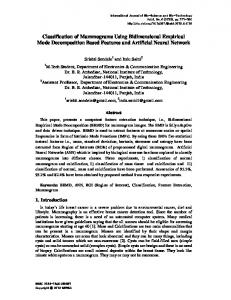
Fig. 1. (b) shows the breast region (white) segmented from the mammogram image shown in (a). (c) illustrates the histogram H of the mammogram, where the threshold value denoted by t0 is selected at the first valley left to the maximum histogram value. Our goal is to obtain the breast boundary by segmenting the breast region from the mammogram. We use histogram thresholding technique to distinguish the bright breast region from the dark background. An example is given in Fig.1, where the indicated threshold t0 identifies the pixels left to it as the background, while the others as the breast region. It’s obvious that the success of the segmentation largely depends on how the threshold value t0 is chosen. A number of strategies to decide the histogram threshold can be found in the literature [6, 7]. In our implementation, we select the threshold t0 as follows: First, the lowest and highest bins of the histogram H
of the mammogram are purposely discarded since they account for the background noise. Then, H is further smoothed by applying a low-pass filter, e.g. median filter or mean filter. After identifying the maximum histogram value pb according to the approach proposed in [4], we choose the threshold t0 as the first valley value left to pb . A example of the segmented breast region using the threshold t0 is shown in Fig.1(b). Since the border of the breast region segmented as above is rather noisy, we smooth it by sequentially applying a pair of morphological operations, closing and opening. An octagonal-shaped operator with radius of 10 is used to preserve the shape of breast region and gives the best smoothing result. Then we can extract the breast skin contour by travelling along the border pixels of the segmented breast region. If the contour is not smooth enough, we will filter it by using cubic B-spline approximation method.
3. MATCHING BOUNDARY POINTS
−3
8
x 10
A1 (H(t)), and the mutual information M I is: M I(A0 , Ah1 ) = −
M M X X
i=1 j=1
p01 h (i, j) log
p01 h (i, j) p0 (i)p1h (j)
in which p0 , p1h represent the corresponding marginal probabilities in A0 and Ah1 , and p01 h denotes the joint probability of (i, j) between A0 and Ah1 . In equation (1), the minimization of the first term M I aims to matching the boundary contours according to the likelihood between their curvatures, while the second term discourages undesirable transformations, which helps to improve the numerical stability. To decrease the dimension of the optimization problem stated in equation (1), we represent h by using cubic B-splines approximation. And the error function is minimized through the gradient descent method. Note that it’s non-trivial to calculate the gradient of the mutual information M I because it depends on the discretized bin values, thus is discontinuous. However, this obstacle can be tackled by estimating M I with Parzen window technique, and an efficient method to evaluate the gradient can be found in work documented in [8].
6
4. EXTRACTION AND MATCHING OF TEXTURE FEATURES
4
curvature
2
0
−2
−4
−6
A0 A
1 h
−8
A1 −10 0.1
0.2
0.3
0.4
0.5
0.6
0.7
0.8
0.9
t
Fig. 2. A0 , A1 represent the discretized curvature functions of C0 and C1 . Ah1 is the curvatures of C1 after being stretched. The deformation of breast skin contours determine how the interior deformation take place to a large degree. Rather than match the boundary points with the assumption of local linear stretching[3], we treat the skin contours as nonlinearly stretchable and align the points on them by maximizing the mutual information between the corresponding curvature functionals. Let C0 , C1 represent the corresponding boundary contours, and c0 , c1 denote their curvature functions, respectively. To facilitate the registration process, C0 , C1 , c0 and c1 are uniformly parameterized to the domain [0, 1], and treated as functionals. We further convert the value of c0 ,c1 into finite bins [1 . . . M ], thus obtain their discretized functional representation as A0 and A1 (see Fig.2). It is obvious that if both A0 and A1 are considered as one dimensional images, the problem of matching boundary points can be converted to one dimensional registration problem. That is, given the discretized curvature functions A0 and A1 , we are asked to find an optimal transformation (or stretching) h : [0, 1] → [0, 1] such that
h = arg min
−M I(A0 , Ah1 )
+λ
Z
1 0
2 ! ∂ (h − t) dt ∂t
where the stretched curvature function, denoted by
Ah1 ,
(1)
is equal to
In order to recover the local deformation in the interior of the breast region, it’s desirable to extract texture-based features and match them between corresponding mammograms. Similar to the selector introduced in [3], where the features with rotation and invariant properties are extracted and steerable filters are used, we propose to employ Gabor filters to detect those features, because they have been reported more robust and more responsive to oriented features [9] than steerable filters. The real Gabor filter kernel oriented at angle θ = −π/2 is defined as: � � �� 1 y2 1 x2 g(x, y) = + exp − cos(2πf x) (2) 2πσx σy 2 σx2 σy2 where the parameters σx , σy and f are decided from the following rules: Let τ be the full-width at half-maximum of the Gaussian term along x axis. Then, σx = τ /2.3, and f = 1/τ . The value of σy is defined as σy = lσx , where l denotes the elongation of the filter along y axis. In current implementation, we empirically set τ = 5 and l = 5. The kernels at other angles can be obtained by rotating (2) over the range [−π/2, π/2]. In our experiment, we used a filter bank of Gabor filters, gk (x, y), k = 0, 1, · · · , 15, oriented at the angles of αk = −π/2 + πk/16. If the a image I(x, y) is processed, the filtered images become Wk (x, y) = (I ∗ gk )(x, y), where the asterisk operator denotes linear convolution. Due to the huge dimension of mammograms, it’s not necessary to detect feature points over the entire breast region. Instead, we constrain the selection done only on certain points, which are decided by Canny Edge Detection technique. Since many overlapping structures exist in mammogram images, the local estimation of feature orientations is not reliable. To this end, we propose that the response Sk (x, y) at pixel (x, y) to the kth Gabor filter is measured as the average of neighboring responses, and defined by: Sk (x, y) =
1 X |Wk (xi , yi )|2 |N | i∈N
(3)
where N represents a 5 × 5 neighborhood. Let Sk1 > Sk2 > Sk3 be the first three largest magnitude of responses in descending order at position (x, y), and the corresponding angles are γ1 (x, y) = αk1 , γ2 (x, y) = αk2 and γ3 (x, y) = αk3 . To find the bifurcate structures among all candidate points, we check for the following condition: γ1 − γ2 < 0.1 γ2 − γ3 If it’s satisfied at a certain point (x, y), we consider there exists a bifurcate structure. Let P and Q be the set of the junction points detected on both mammogram images. The correspondence between between P and Q can be established as follows: 1. Let both mammogram images denoted by I0 and I1 . We estimate two approximate transformations T and T −1 between them, where T mappers from I0 to I1 , while T −1 is its inverse. Note that these mappings can be easily constructed using thin-plate spline approximation, using the boundary correspondences that have been established in section (3). 2. If either P or Q is empty, stop. 3. Pick p as the point with the maximum value of Sk1 from P . Denote its principal and secondary orientation by γ1 (p) and γ2 (p), respectively. Thus the actual angle between them is calculated as: � γ2 − γ1 : γ2 − γ1 > 0 θ(p) = γ2 − γ1 + π : otherwise To improve the robustness of our algorithm, we also compare the nearby intensities of the feature points for best matching. To this end, an additional image region L(p) centered at p with size of 30 × 30 is selected, then after cancellation of shearing and rotation effects, its normalization form R(p) is written by I0 (A(L − p) + p), where A=
�
cos γ1 sin γ1
− cos γ1 / tan θ − sin γ1 − sin γ1 / tan θ + cos γ1
�
4. Let p′ = T (p) be the estimated transformed point of p in I1 . We search in Q for candidate feature point q, such that: 1) |p′ − q| < r1 ; 2) the smallest angle between γ1 (p) and γ1 (q) is less than π/4; 3) |θ(p) − θ(q)| < π/4. r1 is the maximum distance between each pair of feature point, which is set to 20 in our experiment. If we can’t find any candidate in Q, then remove p from P and jump to 2; otherwise, we select the best one, q ¯, whose normalized local image R(¯ q) shares the maximum mutual information with R(p). 5. To avoid condensed feature points, which may introduce large distortion in the recovered transformation, those points in P with distances to p less than r2 are removed; Likewise, the neighboring points to q are also dropped in Q. r2 is the threshold that decides the minimum distance among features points.
(a)
(b)
Fig. 3. (a)(b) show 40 pairs of anisotropic features extracted in the left and right mammograms, respectively.
5. RECOVERING TRANSFORMATION ACCORDING TO ANISOTROPIC FEATURES Each of the feature point extracted above is associated with an orientation that is the principal direction of γ1 . Therefore, for better registration result, it’s more appropriate to align the orientations of the landmarks in addition to the matching of positions[5]. We denote pi and qi the corresponding landmarks in I0 and I1 . Their orientations are represented by two unit vector di and ei , which points to either γ1 or γ1 ± π. Then the transformation u between I0 and I1 can be recovered by solving the following constrained optimization problem: E(u) = M (I0 , I1 , u) + λ1
n X i=1
det (∇uT (pi ))T di , ei
(4)
Where u denotes the transformation to be recovered. The first term M is designed to match the intensity information between two images as much as possible. The criteria, summed squared differences(SSD), is currently incorporated in our current implementation. It is obvious that other metrics, for example, mutual information and correlation, are also possible here. The second term is the penalty for the misalignment between the orientations of corresponding landmarks. Note that (∇uT (pi ))T di is the rotated vector of di after the transformation, which is required to be collinear with ei to register anisotropic information. Note that there is no regularization term included in equation (4). This is because we discretize the transformation field by using cubic B-spline representation, which already has an inherent nature for regularization. To achieve better registration result, we introduce several pseudo landmarks at the image corners and boundaries to avoid unnecessary image floating. In the optimization of equation (4), all of the positional correspondences are treated as hard constraints, which further ensure the correct matching between the orientations associated with landmarks. 6. RESULTS
Our registration framework is demonstrated by matching mammograms from the MIAS digital mammogram database. Three bilateral pairs of left and right images are selected and demonstrated in −1 6. Swap I0 and I1 , P and Q, T and T , then go to 2. Fig.4, representing fatty-glandular tissues (MIAS 015/016), denseFig.3 shows a pair of bilateral mammograms, in which the anisotropicglandular tissues (MIAS 35/36) and fatty tissues (MIAS 75/76) refeatures are extracted using our approach. spectively. The right mammogram is registered to the left one in each
(a)
(b)
(c)
(d)
(e)
(f)
(g)
(h)
(i)
(j)
(k)
(l)
Fig. 4. (a)-(f) represent MIAS15/16(fatty-glandular), MIAS35/36(dense-glandular) and MIAS75/76(fatty) pairs, respectively. (g)(i)(k) show the pre-registration error. (h)(j)(l) demonstrate the post-registration error. The asymmetry structure (highlighted with the blue circle) in (l) is more distinguishable from the surrounding pixels than that in pre-registration error map of (k).
case. The effectiveness of the registration process can be evaluated using comparative measures such as image-subtraction. By comparing pre- and post-registration errors, we found that much of the misregistration in the pre-registration difference image occurs along the periphery of the breast. After the breast boundary points aligned using technique proposed in this paper, most of the peripheral differences can be removed from the subtraction image. In addition, the matching of texture-based anisotropic features selected from the interior of the breast region also helps to further improve the registration result. 7. CONCLUSION In this paper, we presented an automatic imaging framework to register corresponding mammograms with little human intervention. It combines a robust contour-matching algorithm for the matching of breast boundaries, and a novel feature-matching technique, which unwarps corresponding mammograms according to the texture-based anisotropic features automatically selected from the breast region. The experimental results also indicate that the proposed approach can provide useful information for better detection of breast abnormalities. In future, we will test our registration method on real clinical data for further evaluation of its robustness and efficacy.
ACKNOWLEDGEMENTS We gratefully acknowledge financial support from the NIH (1 R01 EB002655-01) and the U.S. Army Breast Cancer Research Program (W81XWH-04-1-0554). 8. REFERENCES [1] F.-F. Yin, M. L. Giger, K. Doi, C. J. Vyborny, and R. R. Schmidt, “Computerized detection of masses in digital mammograms,”
Med. Phy., vol. 32, no. 3, pp. 445–452, 1994. [2] M. Sallam, Image unwarping and difference analysis: a technique for detecting abnormalities in mammograms, Ph.D. thesis, University of South Florida, USA, 1997. [3] M. Y. Sallam and K. W. Bowyer, “Registration and difference analysis of corresponding mammogram images,” Medical Image Analysis, vol. 3, no. 2, pp. 103–118, 1999. [4] T. Ojala, J. N¨appi, and O. Nevalainen, “Accurate segmentation of the breast region from digitized mammograms,” Comp. Med. Imaging & Graphics, vol. 25, pp. 57–59, 2001. [5] K. Rohr, M. Fornefett, and H. S. Stiehl, “Spline-based elastic image registration: integration of landmark errors and orientation attributes,” CVIU, vol. 90, pp. 153–168, 2003. [6] D. H. Davies and D. R. Dance, “Automatic computer detection of clustered calcifications in digital mammograms,” Phys. Med. Biol., vol. 35, pp. 1111–1118, 1990. [7] T. K. Lau and W. F. Bischof, “Automated detection of breast tumors using the asymmetry approach,” Comp. Biomed. Res., vol. 24, pp. 273–295, 1991. [8] Gerardo Hermosillo, Christophe Chefd’Hotel, and Olivier D. Faugeras, “Variational methods for multimodal image matching,” International Journal of Computer Vision, vol. 50, no. 3, pp. 329–343, 2002. [9] F. J. Ayres and R. M. Rangayyan, “Performance analysis of oriented feature detectors,” in Proc. of SIBGRAPI, October 2005, vol. XVIII.