We view automatic robot programming as a trans- ... programming known as assembly plan from obser- ... that demands some intelligence to automate a task.
Automatic Robot Programming by visual Demonstration of Task Execution
and S. Chaudhuri Department of Electrical Engineering, Indian Institute of Technology, Bombay - 400076 M. Yeasin
Abstract- We propose a novel approach to program a robot by demonstrating the task multiple number of times in front of a vision system. The system analyzes the visual data captured during the demonstration of the task by a human operator and produces manipulator level commands, so that the robot can replicate the task. Here we integrate human dexterity with sensory data using computer vision techniques in a single platform. This paper describes a fast and e�cient algorithm for the vision system to process a binocular video sequence to obtain the trajectories of each component of the end-e�ector. The concept of trajectory bundle is introduced to avoid singularities and to obtain an optimal path.
Keywords: Automatic robot programming, trajectory bundle, feature tracking, optimal path, singularities. Introduction I.
Most of today's robots lack the ability to perform satisfactorily, where the object to be manipulated normally exhibit high degrees of variability. Developing a exible robot manipulating system to tackle these uncertainties and to adapt with the frequently changing working environment with minimum operator intervention is of much practical importance[1]. Severe di�culties arise in adapting these systems to apply in di�erent environment due to special nature of the hardware and software. Human beings have the capability to intelligently process these information and the skill to execute these processed information, i.e, tasks. They can perform these tasks with ease, exibility and, of course, with su�cient reliability. Ideally, one wants to have a system that can equally respond like a human being. In many practical systems like exible manufacturing system and robot handling, recon gurability of the robot system is quite crucial. Unfortunately no robot programming language is capable of meeting this mundane requirement. Hence it is of practical interest for some speci c applications (viz, automatic robot programming/ human computer interaction) to incorporate the natural intelligence and
dexterity of human being into the system. It is widely believed [2], [3], [4], [5], [6], [7] that integration of perceptual information with human skill can help in developing a exible autonomous platform for programming a robot. Though the method is quite exible and highly recon gurable and is showing promise to cope with the today's need of the robotic industry, it needs to answer some of the issues include like: how does one generate a sequence of operations? How can a task be described unambiguously? If a task involves grasping, how can a stable grasp be e�ected or shown to be optimal from the "human" or an analytic point of view [4]? Our e�ort in this paper lies circumventing some of these problems during automatic robot programming using moderate quality hardware. We view automatic robot programming as a transformation that translates a task to be performed by robot manipulator to manipulator level commands executable by a robot controller. This paper presents a vision-based method for automatic robot programming by demonstrating the task multiple number of times in front of a stereo vision system. The binocular image sequences are processed to derive the possible trajectories of each component of the end-e�ector. The optimal path could be chosen by the robot controller.
A. Overview of Related Works
A complete automatic programming needs a common platform which can successfully integrate sensory information with human skill. The practical realization of fully automatic programming is di�cult and remain unresolved in a satisfactory manner. Interestingly enough, the recent surge of research works [1], [2], [4], [5], [6], [7], [8] shows the promise that this formidable task can indeed be automated. To this end Kang et al. [4], [7]and Ikeuchi et al. [6] have proposed a method of automatic task programming known as assembly plan from observation (APO). The key idea here is to enable a system to observe a human performing a speci c task, understand it and perform the task with minimal human interference. Later Tso et al. [5] modi ed
and developed a marker based system where mechatronic input device has been used to represent an end-e�ector. The similar approach to program a robot can be found in learning by watching technique developed by Kuniyoshi et al. [8] that tracks movement of a human hand for program generation. Recently, Tung et al. [2] have reported a system which is capable of learning assembly goals automatically. The human user can specify assembly goals to the robot by wearing a Data-Glove and performing the task. The system observes the assembly motion through the signals received from the glove and deduces the assembly goal.
B. Why alternate strategy! A robot programming language is a means by which programmer can express the intended operation of robot and associated activities [9]. However, the level of abstraction at which one must express robot and sensor operations does not ful ll ones expectations. To overcome the disadvantages, Kang et al. [4], [6] proposes a system known as APO. Previous approaches use a special polhemus device which is susceptible to perform poorly in presence of ferromagnetic material while extracting locations of di�erent joints of ngers. They use infrared range detector to estimate depth and use a monocular grey tone image sequence for object recognition and grasp analysis. Teaching the robot involves a proper fusion of all three sensory information. Moreover, demonstrating the task only once does not guarantee that the robot will be able to replicate the task. The path so de ned is not optimal neither in human nor in robot's sense. On the contrary, we use binocular image sequences to recover the su�cient information to generate automatic code for robot controller which is simple, e�cient and computationally less demanding. Ordinary circular shaped markers (tags) are used to locate the joints and nger tips. The feature based stereo vision technique is found to be robust enough to provide the depth estimation. We introduce the notion of trajectory bundle to guarantee a nonsingular optimal path to the robot controller. The organization of the paper is as follows. This paper describes the vision system for automatic code generation in Section II. Section III reports the design and implementation issues of the proposed vision system. Section IV describes experimental results to show the e�cacy of the proposed system. Finally, Section V concludes the paper.
II.
Vision-Based Method of Automatic Robot Programming
Automatic robot programming is an essential component of task automation. Human being acquires this sophisticated skill through learning and training over a long period of time. We do not know what is the exact nature of our skill and strategies. Certainly one thing is clear, that we can apply our intuition and experience at any level of complex situation. This reliability gives us the promise of incorporating human intelligence and skill into a system that demands some intelligence to automate a task. The essential component of the proposed system is shown in Figure 1. In this approach a human opManipulator Work space of robot Joint
Camera
End-effector
Gripper
Objects to be manipulated
Robot Controller
Work space of human Data acquisition system Work Station
Processing Module
Objects to be manipulated
Trajectory selector
Command Generator
Stereo Port
Vision Module
Inverse Kinnematic Module
Calibration Unit
Fig. 1. Block diagram of the proposed system.
erator will demonstrate a particular task that needs to be automated. The operator will perform this task multiple number of times in front of a visual data acquisition system. For the sake of simplicity, we assume that the human operator and the robot are having the similar kind of working environment. The vision module extracts the 3-D image plane Cartesian co-ordinates of di�erent nger tips and wrist joints. We transform the co-ordinates thus obtained to the robot working space co-ordinate. Figure 2 illustrates the transformation to be performed. Let a b 2 3 be the coordinate of a point in frames A and B, respectively. Given b ( operator's workspace) we can de ne a (robot's workspace) by a transformation of co-ordinates: q ;q
R
q
q
q
) (1) where, ab is rotation matrix, ab is translation vector and ab is the transformation. The inverse kinematic solution can be used to translate the Cartesian co-ordinates of the best trajectory once chosen into the corresponding robot joint co-ordinates [10]. The transformed trajectory obtained from mul-
qa
=
Rab qb
R
g
+
Pab ;
more compactly, P
gab
=(
Pab ; Rab
Z
Z
Y Operator’s workspace
B
Pab
R
A
ab
Y X
Robot’s Workspace
q
To chose an optimal path we need to de ne an optimality criterion so that trajectory selection module can select the optimal path lying within the trajectory bundle. For example, one such cost function could be ( )=
X
d j
g ab
Fig. 2. Co-ordinate transformation between work spaces.
XX?
I
i
Y co-ordinate of the feature points
Thumb trajectory bundle
�
K
z
X co-ordinate
of the feature points
J
2
+
K
2�
:( � j
�
Wd
x
z
x
)
(2)
�
J
�
W
i
y
y
k
j
j
� Grab the binocular image sequence of the task
performed by a human operator.
� Find the 3-D Cartesian coordinates of di�er� � � � �
Index finger trajectory bundle
+
where, = jik ? jik?1 , = ikj ? ikj ?1 , � � = ikj ? ikj ?1 . Here, d , , stand for dexterous work-space, index for feature points and frames, respectively, and the superscript denotes the th demonstration. This criterion corresponds to requiring a minimum energy to traverse the distance between the initial and the nal points. Trajectory selection based on feedback from robot might be e�ective in terms of singularity prevention and the constraints related to the degrees of freedom of the manipulator. It may be noted that the kinematics of the robot manipulators are quite different from that of the human demonstrator. Hence the solution may not necessarily be optimal for the robot system. The processed information is then used to generate commands for the robot manipulator to replicate the desired task. Succinctly, the entire procedure can be summarized in the following manner, I
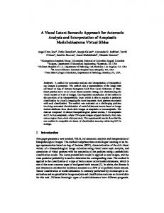
tiple demonstrations are collasced together to construct a `trajectory bundle'. In Figure 3, the conceptual outline of trajectory bundle for thumb and index nger (which is applicable for two nger gripper) has been shown for the sake of clarity. It may be noted here that for each component of tools mounted on the end-e�ector, there is a trajectory bundle and the intersection of any two such bundles for two di�erent tips of the end-e�ector need not be null. Hence, while selecting the optimal trajectory for the robot arm along with its end-e�ector, we must enforce the constraint of maintaining the spatial relationships among all components of the end-e�ector. Further, we may note that for a particular grasping operation, the trajectory bundle for an individual end-e�ector tip may converge to a particular point if and only if the demonstrator grasps the object always at the same location (which is not the case in practice). The exact nature of the bundle would depend on the dexterity of the human operator. It is a very simple task to construct nonsingular trajectory bundle from this arbitrarily de ned trajectory bundle if the dexterous workspace of the robot is known. Trajectory selection module selects the best suitable trajectory from the trajectory bundle thus constructed.
k
2
ent nger tips, wrist, elbow and shoulder joints from the stereo disparity measurement. Repeat it for every frame. Repeat it for every demonstration. Choose the best trajectory lying within the bundle based on feedback from robot controller. Translate the Cartesian coordinates of the chosen trajectories into robot joint co-ordinates. Generate the corresponding manipulator commands through the robot controller.
In this formulation the wrist joint of the operator corresponds to the end-e�ector and each ngertip corresponds to tools component (two nger or multi nger gripper etc.) attached with the manipulator. We also assume that the inverse kinematic solution exists and can avoid singularity if there is any. III.
Design of the Experiment
Fig. 3. Illustration of the concept of trajectory bundle for a It is extremely di�cult to achieve complete autwo nger end-e�ector. The projection from the 3-D to 2-D is shown. tomatic programming of a robot in real time using
existing techniques. One must ensure meeting the alignment so that every joint and nger tip can be following demands, captured with a minimum or possibly with no occlusion while performing the task by the human op� The system must be able to nd appropriate erator. We capture color stereo image sequences of breakpoints in motion, which is equivalent to resolution 320 � 240 pixels of the task execution by saying that it must be able to divide the image the operator. The temporal sampling was selected to sequence into meaningful segments that corre- be about 15 frames/sec. This moderate frame rate sponds to separate human assembly tasks, i.e for capturing data has the following signi cance for perfect temporal segmentation of the image se- the application in hand. quence. � It must understand how to grasp an object if it � It keeps the option open to implement the algohas to follow what a human operator is doing. rithm in real time using a moderate hardware � How should it di�erentiate among various types facility. of task(eg. soft grasp, power grasp etc.)? � It provides consistent tracking of the feature � How to nd a collision free path to manipulate as moderate frame rate guarantees that the the object from one initial place to nal place. occlusion/dis-occlusion is for 2/3 frames which in some sense guarantees a stable tracking. In order to circumvent some of these problems, we use the natural dexterity and skill of human beings. For a faster frame rate the occlusion/dis-occlusion We perform these experiments on a Silicon Graphics may be much higher. As we retain the predicted Indy workstation in o�-line basis. We integrate the point in case of occlusion it may lead to a wrong feature based tracking and the stereo vision tech- tracking result for faster frame rates. The probnique for depth calculation to achieve the desired lem of wrong tracking due to fast frame rate can goal. be partly circumvented by opening a large window centered at the predicted point, increasing the comA. Data acquisition putation thereby. It may be noted that the exact Articulated mechanisms are very di�cult to track value of the frame rate is of no consequence for robot than a single rigid object at least for two reasons. programming purpose, as one needs to de ne only Their state space is larger and their appearance is the trajectory of a joint and not its dynamics. The more complicated [11]. Moreover, it is very di�cult speed of operation can be adjusted through robot to de ne what constitutes a good feature in an artic- controller. ulated mechanism like human hand in motion. To make the matter simple, we attach circular shaped B. Segmentation and feature tracking markers of di�erent colors on di�erent ngertips and We use color segmentation algorithm proposed by hand joints of the operator for the following reasons. Celenk et al. [12] for detecting the colored blobs generated in the image by color stickers. One may � They can be easily xed and they do not a�ect encounter some di�culty in grabbing good quality the movement of the hand. color images to enable a proper segmentation of the � The corresponding image does not change if it color stickers. We establish correspondence between is rotated about the axis of symmetry. di�erent ngertips, and wrist joint based on color � The contrasting material improves the ease of information and the knowledge of the placement of correct detection of a feature. the stickers as shown in Figure 4. We do not pro� The use of color information helps in identifying a particular joint. Yellow
Yellow
Green
Green
We use the centroid of the blobs thus generated in the image plane as our features for tracking. We capture data (sequence of images) by xing the camera parameters and allowing the operator to demonstrate the task in the eld of view of the camera. Fig. 4. Color coding for establishing the correspondences It may be noted that using one stereo pair it is exfor left and right images. This illustrates a four- nger grasping (the little nger has been left out). tremely di�cult to capture occlusion free hand motion data while performing the task. Hence it is desirable to use two stereo pairs with appropriate cess the entire image for tracking purpose, instead Blue
Blue
Red
Left camera view of hand
Green
Red
Right camera view of hand
Green
we use a Kalman lter to predict the tentative feature locations in the successive frames. Hence, we process only a small neighborhood of the predicted location to detect the marker. In case of occlusion, we retain the predicted point as feature point. The algorithm can be succinctly written as, 1. Initialize the trajectory for every joint. 2. Segment the image based on color using color clustering algorithm. 3. Establish both stereo and inter frame correspondence based on color and the knowledge Fig. 5. Sample left and right image from the left and right stereo sequence. of the placement of markers. 4. Predict the th feature point for ( +1)th frame. 5. Process the small neighborhood using step 2-3 and resolve ambiguity if there is any based on Thumb color. 6. Repeat step 2-4 for every feature point. Middle Index 7. Repeat step 2-5 for every stereo frame of the sequence. 8. Repeat step 2-6 for every demonstration. Ring k
After obtaining the inter frame correspondences, we calculate the depth of di�erent ngertips and joints using the standard disparity formula for the stereo vision which can be derived from the geometry of the system. We obtain 3-D information for various nger tips and hand joints for every demonstration and the trajectory bundle for individual feature points are constructed. The optimal path lying within the trajectory bundle can be chosen by considering the kinematic properties of the robot and its end-e�ector. The manipulator is supposed to follow an equivalent of this optimal trajectory in the work space of the robot. We rely on human intelligence based on the assumption that the path human operator will follow will be collision-free. IV.
Experimental Results
We experimented on real, binocular color image sequences to extract the 3-D trajectory information of human hand motion. The ultimate goal we had in our mind is to derive su�cient statistics from the perceptual data. To achieve the goal thus set, we use the tracking algorithm described in Section III on the training image data. Figure 5 shows a representative frame (from both left and right cameras) The sequence was captured by demonstrating the task only once in front of the vision system. Figure 6 shows the trajectory traversed by di�erent nger tips (the perspective projection on an image plane is displayed for clarity. Here we demonstrate a four nger grasp). This result is very signi cant in terms of capturing the hu-
Y co-ordinates of different finger tips
i
380 360 340 320 300 280 260 240 220
0
50
a)
100
150
200
250
300
350
400
X co-ordiates of different finger tips
Fig. 6. Trajectories of di�erent nger tips obtained from training data set for a single demonstration.
man strategy and skill. It is evident in gure 6 that the trajectory traversed by each nger tip has nite number of motion break points. These in some sense re ect the strategy chosen by the human operator while demonstrating the task. These motion break points can be captured from the velocity pro le of the trajectory. These information is invaluable in terms of meaningfully segmenting the task performed by the operator. It may be noted that the end-e�ector orientation can also be determined from this tracking result. As we have mentioned only one demonstration is not good enough for the successful completion of the purpose. We also experimented on multiple demonstration to circumvent the problems related to single demonstration. Figures 7 and 8 shows the trajectory bundle for the thumb and index nger recovered from the training data. Since the trajectory bundle de nes a volume in 3-D, we show a projection of that on the image plane for illustration. It may be noted that for multiple demonstration one can choose different task execution points for every demonstration or may almost stick to the previous task execution point, i.e grasp location. In our experiment we use di�erent grasp locations for each demonstration. It
ing feature correspondences in the binocular video sequence. As we arti cially induce features on the operator's hand (markers) for getting consistent features to track, our calculation of depth is quite accurate. We introduce the notion of `trajectory bundle' to alleviate the problem of encountering singularities in the trajectory. We believe an optimal nonsingular trajectory may help robot to do the task with a desired level of accuracy. We use human intelligence to choose the task strategy and task execution point which automatically ensures a collisionX-Cordinate of the feature point free path. We are working on command generation Fig. 7. Trajectory bundle for thumb obtained from training module by integrating sensor data and human inteldata sets. ligence. 225
Y-Cordinate of the feature point
220
Trajectory bundle for thumb
215 210 205 200 195 190 185 180
175 20
40
60
80
100
120
140
160
180
200
205
Y-cordinate of the feature point
200
References
195
Trajectory bundle of index finger
190 185 180 175 170 165 160 155 150
0
20
40
60
80
100
120
140
160
180
200
X-cordinate of the feature point
Fig. 8. Trajectory bundle for index nger obtained similarly.
is quite clear from trajectory bundles shown in gures 7 and 8 . The choice of task execution point has no importance for the robot controller. These results also validate the proposed tracking algorithm. The information given in gures 6, 7 and 8 corresponds to exact digitary motion of the operator for a single or multiple demonstrations. V.
Conclusion
Automatic programming of a robot implies proper machine translation of a task to be performed by the robot to manipulator level commands. It essentially means that robot has to follow some optimal, collision-free trajectory and it has to execute appropriate commands for grasping/un-grasping and manipulating the object appropriately. In this paper we present a simple, e�cient and robust visionbased system which provides a nonsingular optimal trajectory for robot manipulator. Vision system we proposed in this paper is quite fast as it simultaneously predicts and detects the features to be tracked in the successive frames and it needs to process only a small neighborhood of the predicted points. The use of color information and the digital structure of the human operator simpli es the task of establish-
[1] Y.F Li and M. H. Lee, \Applying vision guidence in robotic food handling ", IEEE Robotics and Automation Megazine, pp. 4{12, March,1996. [2] C. Tung and A. C. Kak, \Integrating sensing, task planning, and execution for robotic assembly", IEEE Tran. on Robotics and Automation, vol. 12, No. 2, pp. 187{201, Apr. 1996. [3] S. K. Tso and K. P. Liu, \Hidden markov model for intelligent extraction of robot trajectory command from demonstrated trajectories", in Proc. IEEE International Conf. Industrial Technology, 1996, pp. 294{298. [4] S. B. Kang and K. Ikeuchi, \Towards automatic robot instruction from perception- temporal segmentation of task from human hand motion", IEEE Tran. on Robotics and Automation, vol. 11, No.5, pp. 670{681, Nov.,1995. [5] S. K. Tso and K. P. Liu, \Automatic generation of robot program codes from perception of human demonstration", in Proc. IEEE/RSJ International Conf. Intelligent Robots and Systems, Vol. 1, Pittsburgh, Pennsylvania, USA, Aug., 1995, pp. 23{28. [6] K. Ikeuchi and T. Suehiro, \Towards an assembly plan from observation part I: Task recognition with polyhedral object ", IEEE Tran. on Robotics and Automation, vol. 10, pp. 360{385, Oct.,94. [7] S. B. Kang and K. Ikeuchi, \Towards automatic robot instruction from perception- recognizing a grasp from observation", IEEE Tran. on Robotics and Automation, vol. 9, No.2, pp. 432{443, April,1993. [8] Y. Kuniyoshi, H. Inoue, and M.Ibana, \Learning by watching:extracting reusable task knowledge from visual observation from human performance", IEEE Tran. on Robotics and Automation, vol. 10, No.3, pp. 799{822, June, 1994. [9] R. A. Volz, \Report of the robot programming working group: Nato workshop on robot programming languages", IEEE Tran. on Robotics and Automation, vol. 4, No. 1, pp. 87{89, Feb., 1988. [10] R. J. Vaccaro and S. D. Hill, \Ajoint-space command generator for cartesian control of robotic manipulators", IEEE Tran. on Robotics and Automation, vol. 4, No. 1, pp. 71{77, Feb., 1988. [11] J. M. Rheg and T. Kanade, \Visual tracking of high dof articulated structures:an application to human hand tracking", Lecture notes on computer science series, vol. EECV, Stockholm, Sweden, pp. 35{46, 1994. [12] M. Celenk, \Color clustering for image segmentation", IEEE Robotics and Automation Megazine, pp. 4{12, March, 1989.