In order to retain correctness of the model down to the software executed on a ..... dispatching of tasks according to the calculated schedule. The dispatching ...
Optimizing Automatic Deployment Using Non-Functional Requirement Annotations Stefan Kugele12 , Wolfgang Haberl1 , Michael Tautschnig2 , and Martin Wechs3 1
Institut f¨ ur Informatik Technische Universit¨ at M¨ unchen Boltzmannstr. 3, 85748 Garching b. M¨ unchen, Germany 2 Institut f¨ ur Informatik Technische Universit¨ at Darmstadt Hochschulstr. 10, 64289 Darmstadt, Germany 3 BMW Forschung und Technik GmbH Hanauer Straße 46, 80992 M¨ unchen, Germany
Abstract Model-driven development has become common practice in design of safety-critical real-time systems. High-level modeling constructs help to reduce the overall system complexity apparent to developers. This abstraction caters for fewer implementation errors in the resulting systems. In order to retain correctness of the model down to the software executed on a concrete platform, human faults during implementation must be avoided. This calls for an automatic, unattended deployment process including allocation, scheduling, and platform configuration. In this paper we introduce the concept of a systems compiler using nonfunctional requirements (NFR) as a guidance for deployment of real-time systems. The postulated requirements are then used to optimize the allocation decision, i. e., the process of mapping model entities to available computing nodes, as well as the subsequent generation of schedules.
1
Introduction
By far the largest part of computer systems today is used in embedded systems (98%) [1]. These are integrated in laundry machines, medical systems, cars, and aircrafts, just to name a few. In this paper we focus on large scale distributed embedded systems, built up from dozens or even hundreds of computing nodes, interconnected by various bus systems. Such systems contain or constitute lifecritical electronic resources. Faults, of any kind, thus may be fatal. Even if not fatal, they bare large warranty costs for the designers and integrators of the product. The design methodology described in this paper tries to reduce the error rate of problems resulting from implementation errors. We do not consider bugs in specifications or byzantine software failures due to hardware errors, but extensions proposed to alleviate such issues may well be integrated. Today, model driven development (MDD) is an established means of tackling the enormous complexity involved in designing distributed embedded systems. The large scale prohibits engineers from grasping the entire system at once.
Rather, a hierarchy of abstractions is applied to attain manageability at each given level of abstraction. Pretschner et al. [2] for example consider three layers of abstraction: a model of system features (requirements), a logical view (system behavior), and a technical architecture (description of the target platform). At higher levels of abstraction, even full formal verification, e.g., using model checking, can be applied to guarantee adherence to a set of properties. Then, proper behavior at model level may be guaranteed. In case of embedded real-time systems, however, the target platform to operate on likely invalidates several assumptions made at model level, or exposes properties that are not captured by functional/behavioral modeling. We call such properties non-functional requirements, which includes the description of the target platform, or supplier specific artifacts (see Section 3). The complexity of the modeled system not only necessitates proper abstractions, but also calls for automation to take a model to an executable object, and later to a functional integrated system. An automated translation likely reduces errors and further guarantees reproducible results, and thus improves overall quality. Such an automatism, however, must be made aware of all requirements concerning the translation, which to a large extend involves non-functional requirements. In this paper we describe concepts and implementation, both for specification of non-functional requirements and the automated translation from behavioral models down to the effective runnable. The process of translation is best compared to that of a software compiler. Given a functional model, usually as a piece of source code, a runnable entity is produced. Compiler and linker will be given all constraints imposed by the operating system and the target hardware platform to obtain an appropriate piece of software. Apart from the straightforward translation, a fundamental job of today’s compilers is optimization in terms of size and execution speed. In embedded systems, we will call this process systems compilation, since the compilation will be accomplished for the overall system model where the involved software and hardware components may be of various types. Here, both
Non-functional requirements Functional model
Clustering
Code generation
Allocation
Scheduling
Platform configuration
Platform model
Figure 1. Systems compilation steps
translation and optimization are by no means straightforward. As per translation, a heterogenous heap of models and requirements must be considered to obtain a valid runnable entity (cf. [3]). Today, a certain level of black magic performed by engineers is required to fit the software and hardware components
into the targeted vehicle. In this paper, additional non-functional requirements are considered with the objective of a cost optimized system. In Figure 1 we outline the process of automated systems compilation as described in this paper. We propose non-functional requirements be annotated to the functional models. The obtained executables are tailored towards the specific platform and require no further manual intervention. 1.1
Related Work
Annotation of non-functional requirements and a notation of platform capabilities was described by Dinkel and Baumgarten [4]. Their goal, however, was the dynamic system reconfiguration at run-time. We not only model these nonfunctional requirements and capabilities, but describe a fully automatic deployment process. This process ranges from a system design modeled in the language COLA (Component Language) [5], to determination of optimal allocation with respect to an optimization goal and pre-runtime scheduling. Wuyts and Ducasse instrument components, with non-functional requirements, specified in Comes (a general Component Meta-Model) [6]. In Comes, components are seen as black boxes annotated with properties. This may be sufficient for allocation and scheduling, but lacks the information necessary for model-checking and other verification techniques. In COLA, each level of abstraction—from a very high-level system design down to the low implementation level—offers a white-box view and therefore provides all necessary information. The UML profile MARTE (Modeling and Analysis of Real-Time and Embedded Systems) [7] is currently in the course of standards definition. Therefore, Espinoza et al. proposed an annotation of UML models with non-functional properties [8]. UML, however, is a general purpose language, which does not cater for the specific needs of the sub-domains of embedded systems design, like automotive or avionics industry. In [1], Broy objects and favors the use of domain specific languages and architectures to improve the state of the art. We present COLA as such a domain specific language, which, in contrast to UML, also features a unique formal semantics. Moreover, Matic et al. [9] take platform specifications, e.g., power modes of the micro-controller, into account, as well as application specific information like periods of tasks, in order to generate an optimal scheduling. Compared to our approach, their work starts from having tasks to schedule. Our approach, however, supports an integrated development process of distributed hard real-time systems from requirements engineering (system features) over the design phase to the actual code generation, task allocation and scheduling in a consistent modeling formalism. Furthermore, we optimize an objective function subject to certain constraints stemming from non-functional requirements. Regarding the overall design process, the DECOS project [10] is closest to our approach. Unlike COLA, however, they do not use a consistent modeling formalism, but rather resort to various techniques.
1.2
Organization
The rest of the paper is structured as follows. The next section gives a brief introduction to the Component Language (COLA). In Section 3, we discuss different non-functional requirements. Section 4 introduces the platform model used throughout this paper with its annotated requirements and capabilities. The optimized automatic deployment process is described in Section 5. Allocation and scheduling are mentioned as well as the concluding platform configuration. Finally, conclusions of the presented work are given in Section 6.
2
COLA—The Component Language
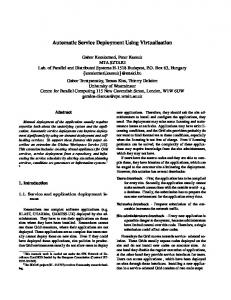
During the past years, synchronous data-flow languages have become increasingly popular tools for the description and design of safety-critical embedded control-systems. Like MATLAB/Simulink [11], the industry standard CASEtool, or SCADE by Esterel Technologies (A380, FCS) [12], COLA uses data-flow networks to describe complex automotive and avionics systems. Approaches for model-based development and design for embedded control systems based on the synchronous paradigm have been described in [13, 14]. In synchronous dataflow languages, components work in parallel with respect to data dependencies and process their input and output values at clock ticks, i. e., discrete time points. In COLA, similar to other approaches following the hypothesis of perfect synchrony [15] it is assumed that communication of data via connections—in COLA, they are called channels—as well as computation of data-flow networks elapse infinitely fast and therefore take no time. In this paper we use the synchronous data-flow language COLA, which supports both a graphical and textual syntax and is based on a rigorous semantics. The key concept of COLA are units. Units are at the very heart of the COLA syntax definition because all COLA models are built up by units and form data-flow networks. A unit itself can further be decomposed into sub-units in a hierarchical fashion and build up complex networks. The lowest level of those hierarchical networks consist only of so-called basic blocks that provide basic arithmetic and comparison operators. Environmental interaction is given via typed ports. In addition to basic blocks and networks, units can be decomposed into automata, i. e., finite state machines similar to Statecharts [16]. The behavior in each state is again determined by units corresponding to each of the states. This capability is well suited to express disjoint system modes, also called operating modes (cf. [13, 17, 18]). Figure 2 shows a COLA system implementing parts of an ignition with its states ignition on and ignition off. The state ignition on is further decomposed in this example. Furthermore, COLA includes a special unit, called delay, to retain data for one clock tick. In this way, memories and feedback-loops can be realized. To make distributed execution of COLA models possible, a partitioning into runnable software components has to be accomplished. These components are referred to as clusters in the context of COLA.
ignition ignition on
ignition off
ignition on some further decomposition 100
Figure 2. Fictive ignition modeled in COLA using operating modes
3
Non-Functional Requirements
In requirements engineering of software systems, we distinguish functional and non-functional requirements. Functional requirements cover all requisites necessary for the correct evaluation of the specified algorithms, i. e., the mathematical functions. These mainly depend on the availability of input data. Contrariwise, non-functional requirements cover all additional demands, which are specified for a piece of software and which do not directly influence the resulting output data. They are measurable such that their compliance can be checked. In this paper, we further distinguish two kinds of non-functional requirements: first, non-functional requirements that are essential for a correct operation of the specified system are considered. If at least one of these requirements is not satisfied, an error-free operation of the overall system cannot be guaranteed. Second, we consider non-functional requirements that are not necessary for the system to operate, but rather improve a system’s quality regarding timely execution (i. e., preservation of deadlines), resource usage, redundancy, etc. Some possible quality requirements are given in ISO 9126. For example, it could be beneficial to allocate safety-critical tasks onto processors on different, redundant electronic control units (ECU). Another requirement might be to allocate all tasks implemented by the same third-party supplier onto the same ECU, resulting in a simplified maintenance process. We use the terms processor and processing unit interchangeably and mean a CPU or DSP without RAM, ROM, etc., whereas an ECU may include several processors, RAM, ROM, and is connected to sensors, actuators and buses (cf. Figure 4). The NFRs mentioned here are intended to show the use of our methodology. Of course, more than the discussed NFRs can be taken into account and easily integrated in both the described model and the used allocation and scheduling algorithms.
3.1
Essential Non-Functional Requirements
In the following, we briefly outline those NFRs that are essential for a correct operation of the overall system. Computing power: Each cluster needs a certain amount of computing power for execution. This amount is annotated to the cluster embodying its worstcase requirement. Hence this requirement can be checked against the given platform. If more clusters are allocated onto a single processing unit than it can handle, not all clusters are guaranteed be be evaluated. Memory: Similarly to computing power, a cluster needs a minimum amount of available memory. Two forms of memory are consumed: first, the binary file generated for a cluster has to be stored in the permanent storage (ROM) of the ECU. Second, the code generated for the cluster has demands regarding the RAM available during execution. Power state: Typically, embedded systems are bound to limited power supply. Hence huge efforts are put into research and development of power saving technologies. For distributed embedded systems like cars, this can be achieved through the definition of different power states. According to the actual state of the car, e.g. locked, ignition off, ignition on, a varying number of ECUs might be active. Other nodes are shut down at the same time to avoid a waste of power. To distinguish power states, a state hierarchy is given. Each power state defines the set of ECUs running in it. Each higher state contains the same ECUs, and at least one additional more. Therefore the relation S0 ⊂ S1 ⊂ S2 ⊂ S3 indicates four power states which S0 being the lowest state and S3 being the highest state in that example. 3.2
Auxiliary Non-functional Requirements
In addition to the mentioned essential NFRs, we also address auxiliary NFRs. These are not necessary for correct operation, but raise further demands on the system that, e.g., lower its cost or improve its efficiency. Supplier: Large scale embedded systems are often the result of a cooperation of several partners in industry. When defining a model for the whole system, the definition of work packages for the different team partners is desirable. These could consist of several clusters each in case of COLA. To allow for this partitioning the designated partner can be annotated to each cluster of the model. The supplier information can then be used to allocate tasks implemented by a single supplier exclusively onto the same ECU(s). This approach enables the partners to retain their current work-sharing where each partner implements a piece of hardware, e.g., an ECU, together with the corresponding software. Redundancy: Dealing with safety-critical hard real-time systems, demands for the implementation of error correcting techniques in case of a system node’s failure emerge. A frequently used technique for error masking is the use of
redundant software components, specified using clusters in our case. The specification of a redundancy requirement defines the number of redundant cluster copies to use in the system, i. e., on how many different ECUs a cluster should be deployed. Processor architecture: If a cluster’s implementation is dependent on a specific processor’s capabilities, e.g. a digital signal processor (DSP), the cluster has to be placed accordingly. This might be necessary for implementations of algorithms requiring a large amount of processing power without violating given deadlines. Cost: From an economical point of view, one of the most important NFRs are costs. In the automotive domain, for example, manufacturers operate in a highly competitive mass market with strong cost pressure. Therefore, the major part of the presented optimization approach is guided by costs. In this paper cost is seen from the manufacturer’s point of view. In some cases it may be beneficial to assemble more processors than needed to fulfill the desired functionality, only to reduce the overall system costs. It is due to the optimization process to decide on the most economic solution.
4
Requirements and Capabilities Meta-Models
In order to allow for an automatic transformation of the modeled COLA system into an executable system, algorithms for allocation and scheduling of clusters are needed. Their evaluation is influenced by the NFRs specified in the COLA model. Thus each cluster of the COLA model may be annotated with several NFRs. In the following we detail on the meta-model for specification of cluster requirements and platform capabilities. Requirements Specification Cluster requirements are captured as annotations in the system model. These annotations occur in two forms: first, annotations like power states, call frequency, etc. can be set. The values given for these requirements are fixed independent of the processor the cluster is deployed. Second, cluster requirements annotations that are specific for each processing unit the cluster is deployed to, can be defined. For example, consider the number of computing cycles and the memory consumption. In contrast to simple NFRs, these requirements are specific for each processor on an ECU, because the values differ for the processor architecture, memory segmentation, etc. used on the ECU in question. Therefore, these values have to be defined for each possible allocation target. Thus these requirements are given for the cluster as a set of tuples, each tuple consisting of the addressed node and the according value of the requirement for that node. A class diagram of the meta-model for clusters and their requirement annotations is given in Figure 3. As depicted, the requirements presented in Section 3 are covered in this meta-model. Simple annotations are added to the clusters as attributes. In order to allow for a matching of these requirements and the platform capabilities, a unit for the requirement has to be chosen for each value. For example, the redundancy requirement for a cluster
Cluster call_periode : int replicas : int supplier : String pu_type : String power_state : int deadline : int Memory RAM_req : int ROM_req : int
ECU
NFR
ProcessingTime cpu_cycles : int
Figure 3. Cluster annotation model
is specified by giving the number of needed copies. Other values may be represented by sets, e.g., the specification of clusters implemented by a single supplier. Besides these simple requirements, node specific requirements are covered by the meta-model. As their values differ according to each node the cluster might be deployed to, the requirements are stored in an association class. Therefore, distinct values are stored for each possible cluster allocation onto a system’s node. A complete list as well as an explanation for the attributes covered in Figure 3 is given in Table 1. Capabilities Specification In order to calculate allocation and scheduling decisions, the capabilities of the platform have to be given. These capabilities are Table 1. Table of NFRs and capabilities Requirement
Unit
cpu cycles
(ID, cycles)
RAM req ROM req power state supplier replicas
kByte kByte Name Name Instances
pu type deadline
Set ms
Capability
Unit
cost ROM cap RAM cap os overhead
Euro kByte kByte ms
power state
State
supplier pu arch
Name Name
proc cycles
Cycles/ms
Description The amount of processing cycles needed is specific for every processor in question. Thus the value is specified as a tuple mapping the processor ID to a number of cycles. The dynamic memory demand during task execution. The memory needed for binary file storage. Name of the lowest power state in which this task is active. The name of the supplier implementing this cluster. The number of copies distributed over the system for redundancy reasons. The names of valid processor architectures. Specifies a deadline within a cluster has to be executed. Description The cost generated by using this hardware component. The amount of permanent memory available on the node. The working memory available on the node. For every called task, a certain amount of operating system overhead is generated for dispatching, memory management, etc. An ECU is active in the specified power state and all higher power states. The name of the supplier building this piece of hardware. Processing units differ by their respective processor architecture. Thus general purpose processors, DSPs and others can be distinguished. To state the amount of processing power available, the number of cycles per milliseconds is given.
stored as an extension of the platform model, which include hardware, software and other aspects. The algorithms described in Section 5 rely on the availability of this information. While most capabilities are used as constraints for choosing valid allocation and scheduling schemes, the cost attribute has to be handled differently. It allows for an optimization of the resulting allocation and scheduling plan by calculating the most economic system architecture. The complete list of platform model attributes, and an explanation of these, is given in Table 1. The attributes are taken from the COLA platform metamodel, which can be seen in Figure 4 System
1
Bus
1..* cost : int
1
connectedTo
2..*
ProcessingUnit pu_arch : String proc_cycles : int cost : int
1..*
1
ECU ROM_cap : long RAM_cap : long os_overhead : int power_state : int supplier : String cost : int 1
* Sensor
1
1..*
BusInterface cost : int
1 * Actuator
Figure 4. Platform model
5
Deployment Process
The aim of a fully automatic deployment process is bridging the gap between the system description—in our case, in a model-based fashion—and the target platform without a need for human interaction. As the system is modeled without taking distribution aspects into account, a division of software components into cluster—the model representation of software tasks—and an allocation of these onto processing units is defined. A clustering is derived from an optimized software architecture w.r.t. reusability, maintainability, design guidelines, documentation and others (cf. [19]). Subsequently, a static schedule for the tasks on each node is defined and the appertaining C code is generated. Finally, the execution platform has to be configured, regarding addressing of messages, buffer allocation, etc. In the following, we will briefly introduce these steps. 5.1
Allocation
Our approach focuses on an optimized automatic deployment process for embedded hard real-time systems w.r.t. a set of given non-functional requirements. In
Section 4, we introduced a meta-model for annotating systems with NFRs. These requirements are now taken into account by the presented allocation algorithm. Similar to Zheng et al. [20] and Matic et al. [9] we use an integer linear programming (ILP) approach and therefore chose a similar nomenclature. In addition to Zheng et al., Metzner and Herde [21] who are using a SAT-based approach for the task allocation problem, our approach takes non-functional requirements during the deployment process into account. Before listing a set of constraints and defining the optimization function, we introduce the notation used in this section. Notation Let T denote the set of all clusters (tasks), and let P be the set of all processing units. In the following, we use the indicator variable at,p where t ∈ T is a task and p ∈ P is a processing unit to indicate where a task is deployed to: ( 1 if task t is allocated to processor p at,p = 0 otherwise. Furthermore, as abbreviating notation for the set {t | t ∈ T ∧ φ(t)}, where φ is some predicate over model attributes, we write t|φ , e.g., p|supplier=s ≡ {p | p ∈ P ∧supplier(p) = s}. Variable names written in sans serif font refer to attributes of the platform model shown in Figure 4 and the cluster annotation model depicted in Figure 3, respectively. In the following, we refer to several sets of model artifacts: ECU (electronic control units), P (processing units), PA (processor architectures), T (tasks), PS (power states), and S (suppliers). Constraints 1. The following essential NFRs have to be met: (a) Computing power: For all processing units p ∈ P it holds X at,p · (cpu cycles(t, p) + os overhead(p)) · ̺ ≤ proc cycles(p) t∈T
where ̺ defines the number of task invocations per time unit. (b) Memory consumption: For all ECUs e ∈ ECU it holds X X at,p · RAM req(t, p) ≤ RAM cap(p) p∈proc(e) t∈T
X
X
at,p · ROM req(t, p) ≤ ROM cap(p)
p∈proc(e) t∈T
where proc(e) returns a set of processors present at ECU e. (c) Power states: For all power states ps ∈ PS and all tasks t|power state=ps it holds: X at,p = N p|power state≥ps
2. Auxiliary non-functional requirements: (a) Supplier: For all suppliers s ∈ S and all tasks t|supplier=s holds: X at,p = N p|supplier=s
(b) Redundancy: Each cluster has to be deployed onto N processing units. If no redundancy annotation is given, then N = 1, otherwise N = replicas(t). This holds for all tasks t ∈ T . X at,p = N p∈P
(c) Processor architecture: For all processor architectures pa ∈ PA and all tasks t|pu arch=pa it holds: X at,p = N p|pu arch=pa
(d) Communication costs: Inter- and intra-processor communication may be important in a real-time system to guarantee certain deadlines. We t ,p introduce indicator variables atji ,puv which are 1, if task task ti is deployed onto processor pu and task tj onto processor pv , and 0 otherwise. It holds: t ,p atji ,puv ⇐⇒ ati ,pu ∧ atj ,pv . Formulated as linear constraints we get for all 1 ≤ i, j ≤ |T | and 1 ≤ u, v ≤ |P |: t ,p
−ati ,pu − atj ,pv + atji ,puv > −2
and
t ,p
− 2 atji ,puv + ati ,pu + atj ,pv ≥ 0
These indicator variables are then multiplied by measured costs for interand intra-ECU communication. These costs include, amongst others, the communication frequency. Both, indicator variables and costs form the basis for a possible metric in the optimization function. (e) Costs: Hardware is an important expense factor. Hence unused components like controllers, buses and connection interfaces are only assembled if for example the costs for future extensions are then reduced. If a bus is exclusively used by unnecessary nodes, i. e., no tasks are mapped onto them, it can be economized. This scenario, which is representative for similar dependencies, can be expressed as follows: ∀t ∈ T ∀p ∈ P
− at,p + cp > −1
where cp ∈ {0, 1} indicates that the expense for processor p has to be taken into account during the optimization process. This decision implies that costs for the involved connection interfaces etc. have to be considered: ∀p ∈ P − cp + cb > −1 where cb ∈ {0, 1} is an indicator for the costs due to processor p being connected to the bus b via a connection interface.
(f) Fixed allocation for some other reason: If a task t ∈ T has to be allocated onto a special processor p, then at,p = 1 has to be added as constraint. All the mentioned constraints, and other conceivable constraint extensions have to be fulfilled such that it is possible to find an (optimal) solution. Additional requirements include for example maintainability, extensibility and locality of input/output hardware. Maintainability demands for a placement of related tasks onto the same or a small number of ECUs. This results in fewer system nodes involved in software maintenance activities. Considering future functionality improvements, it may be beneficial to include some spare system capacity. This can be achieved by introducing dummy clusters. Regarding bus communication, it is convenient to place tasks involved in environmental interaction on the ECU the respective sensors and actuators are connected to. To allow for optimization, in the following an objective function is given. Optimization Function Beside the given constraints, it is mandatory to define an optimization function. It consists of the two main components costs and metrics. Costs characterize actual expenses whereas metrics subsume non-functional optimization factors like memory, CPU time, or communication costs. minimize s.t.
X j
λj · costj +
X
µk · metrick
k
P E.g., the costs for processors costproc sum up to: costproc = p∈P cp · κp , where κp is the cost per unit obtained from the bill of material (BOM). By setting an upper and a lower bound for costj and metrick , outliers during optimization are avoided. Metrics can be gained in a similar way. The distinct but fixed weightings λj and µk enable to characterize OEM’s optimization criteria. Criteria for this parameter selection will be subject to subsequent work. Hereby, statistical processes as well as methods from financial mathematics are involved. 5.2
Scheduling
In this paper we describe a static, i. e., offline approach, which is comparable to the work of Schild and W¨ urz [22], but in contrast, our approach optimizes the result w.r.t. costs and other metrics. To realize the modeled system, the assumption we made on the logical architecture—the complete system is evaluated in zero time and operate at discrete ticks—is replaced by deadlines specified in the model. As long as all active clusters are evaluated and all their deadlines are met, the time assumption can be seen as fulfilled. Hardware interaction has to be handled in a specific way to converge towards the synchrony assumption. Assuming this hypothesis, all sensors and actuators are read from or written to, respectively, at the same instant of time. In a car, however, this cannot be achieved, as a parallel reading of several sensors connected to the same ECU is technically impossible. For example, consider the four wheel speed sensors providing rotation values used for
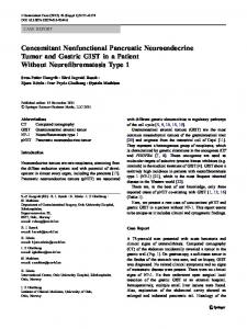
the electronic stability control task. A lag in reading times beyond a certain threshold would lead to malfunction. Therefore, we propose a scheduling cycle starting with reading all sensors, subsequent execution of application tasks, and finally the writing of all actuators. This conforms to the described scenario as close as possible. Figure 5 illustrates such a scheduling cycle. The generation of
read sensors
write actuators
ECU1
t... t2
ECU2 ECU3
t1
tn
scheduling cycle
Figure 5. Scheduling cycle
schedules is—among other prerequisites—guided by the causal order of clusters. This causality can be derived from the data-flow defined in the COLA model and depicted in a cluster dependency graph (CDG), as described in [19]. Since allocation and scheduling are separated, the scheduler already knows about task distribution. This separation may result in a worse result compared to a combined approach, but seems to be more feasible. The challenge remains to find an optimal schedule for the complete system, preserving the model semantics. The objective is to minimize: X f: tc(t) t∈T
where tc(t) defines the completion time of task t taken from the set of all tasks T . Our algorithm is implemented in a way that all tasks of the distributed system are scheduled to have their completion times as early as possible w.r.t. possible data dependencies. This procedure causes a compaction of tasks at the beginning of the schedule cycle. The possibly remaining cycle time can be used in future extensions to schedule aperiodic and sporadic tasks. 5.3
Platform Configuration and Execution
Subsequent to scheduling, C code for the modeled system is generated. As mentioned before, a cluster is the model representation of a task. Thus a single source file is generated for each cluster by our code generator [23]. The automatic generation of code guarantees the conformance of the C code to the COLA model.
Comparing the overall system model designed in COLA and its realization in software, obviously a mapping from COLA channels to communication between tasks has to be defined. In a distributed system this may be local communication as well as bus communication. The data dependencies are captured in a task graph [19] in the COLA modeling process. It is our intention to allow for a flexible distribution of tasks without defining static communication addresses. This is realized using a communication middleware for all task interactions as well as task state storage. Additionally, the middleware is responsible for the dispatching of tasks according to the calculated schedule. The dispatching plan, as well as the task to address mapping is generated unattended, and therefore avoids manual faults. We employ our middleware [24] for mapping channels to communication.
6
Conclusions
In this paper, we introduced an integrated model-driven development process for embedded real-time systems. We outlined the necessary steps for getting from a functional system design modeled with COLA to a runnable entity. The metaphor of a systems compiler best describes this process. First, the model is cut into clusters which are subsequently allocated onto the available processing units. Afterwards, an optimal schedule for the complete system is calculated. By annotating the model with non-functional requirements, we were able not only to find a feasible solution, but even an optimal solution for both task allocation and task scheduling, respectively, w.r.t. the given NFRs. The unattended platform configuration tops the process off. Using this deployment process, an adaptive cruise control system (ACC) was realized on the LEGO Mindstorms platform as well as a parking assistance using several interconnected gumstix microcontrollers with a RTOS installed.
References 1. Broy, M.: Automotive software and systems engineering (panel). In: MEMOCODE. (2005) 143–149 2. Pretschner, A., Broy, M., Kr¨ uger, I.H., Stauner, T.: Software engineering for automotive systems: A roadmap. In: FOSE ’07. (2007) 55–71 3. Henzinger, T.A., Sifakis, J.: The discipline of embedded systems design. IEEE Computer 40(10) (2007) 32–40 4. Dinkel, M., Baumgarten, U.: Modeling nonfunctional requirements: a basis for dynamic systems management. SIGSOFT Softw. Eng. Notes 30(4) (2005) 1–8 5. Kugele, S., Tautschnig, M., Bauer, A., Schallhart, C., Merenda, S., Haberl, W., K¨ uhnel, C., M¨ uller, F., Wang, Z., Wild, D., Rittmann, S., Wechs, M.: COLA – The component language. Technical Report TUM-I0714, Institut f¨ ur Informatik, Technische Universit¨ at M¨ unchen (September 2007) 6. Wuyts, R., Ducasse, S.: Non-functional requirements in a component model for embedded systems. In: SAVCBS 2001. (2001)
7. Object Management Group: Uml profile for modeling and analysis of real-time and embedded systems (marte). OMG document: ptc/07-08-04 (2007) 8. Espinoza, H., Dubois, H., G´erard, S., Pasaje, J.L.M., Petriu, D.C., Woodside, C.M.: Annotating uml models with non-functional properties for quantitative analysis. In: MoDELS Satellite Events. (2005) 79–90 9. Matic, S., Goraczko, M., Liu, J., Lymberopoulos, D., Priyantha, B., Zhao, F.: Resource modeling and scheduling for extensible embedded platforms. Technical Report MSR-TR-2006-176, Microsoft Reasearch, One Microsoft Way, Redmond, WA, USA (2006) 10. Kopetz, H., Obermaisser, R., Peti, P., Suri, N.: From a federated to an integrated architecture for dependable embedded real-time systems. Technical Report 22, Technische Universit¨ at Wien, Institut f¨ ur Technische Informatik, Austria (2004) 11. The MathWorks Inc.: Using Simulink. (2000) 12. Berry, G., Gonthier, G.: The esterel synchronous programming language: design, semantics, implementation. Sci. Comput. Program. 19(2) (1992) 87–152 13. Bauer, A., Broy, M., Romberg, J., Sch¨ atz, B., Braun, P., Freund, U., Mata, N., Sandner, R., Ziegenbein, D.: AutoMoDe — Notations, Methods, and Tools for Model-Based Development of Automotive Software. In: Proceedings of the SAE 2005 World Congress, Detroit, MI, Society of Automotive Engineers (April 2005) 14. Caspi, P., Curic, A., Maignan, A., Sofronis, C., Tripakis, S., Niebert, P.: From simulink to SCADE/lustre to TTA: a layered approach for distributed embedded applications. In: LCTES, ACM (2003) 153–162 15. Halbwachs, N., Caspi, P., Raymond, P., Pilaud, D.: The synchronous data-flow programming language LUSTRE. Proceedings of the IEEE 79(9) (September 1991) 1305–1320 16. Booch, G., Rumbaugh, J., Jacobson, I.: The Unified Modeling Language User Guide. Addison-Wesley (1998) 17. IEEE: IEEE Std 830-1998: IEEE Recommended Practice for Software Requirements Specifications. Institute of Electrical and Electronics Engineers (1998) 18. Maraninchi, F., R´emond, Y.: Mode-automata: a new domain-specific construct for the development of safe critical systems. Science of Computer Programming 46(3) (2003) 219–254 19. Kugele, S., Haberl, W.: Mapping Data-Flow Dependencies onto Distributed Embedded Systems. In: SERP 2008, Las Vegas, Nevada, USA (July 2008) 20. Zheng, W., Zhu, Q., Natale, M.D., Vincentelli, A.S.: Definition of task allocation and priority assignment in hard real-time distributed systems. In: RTSS ’07, Washington, DC, USA, IEEE Computer Society (2007) 161–170 21. Metzner, A., Herde, C.: Rtsat–an optimal and efficient approach to the task allocation problem in distributed architectures. In: RTSS. (2006) 147–158 22. Schild, K., W¨ urtz, J.: Off-line scheduling of a real-time system. Proceedings of the 1998 ACM symposium on Applied Computing (Jan 1998) 23. Haberl, W., Tautschnig, M., Baumgarten, U.: Running COLA on Embedded Systems. In: IMECS 2008. (March 2008) 24. Haberl, W., Baumgarten, U., Birke, J.: A Middleware for Model-Based Embedded Systems. In: ESA 2008, Las Vegas, Nevada, USA (July 2008)