ICSEA 2012 : The Seventh International Conference on Software Engineering Advances
Automatic Synthesis of Hardware-Specific Code in Component-Based Embedded Systems Luka Lednicki, Ivica Crnkovi´c M¨alardalen Real-Time Research Centre M¨alardalen University V¨aster˚as, Sweden Email: {luka.lednicki,ivica.crnkovic}@mdh.se
Abstract—In recent years, there has been a clear trend in research and practice to bring benefits of component based development into the embedded systems domain. However, one often neglected aspect in component models is support for integration of hardware devices like sensors and actuators. In most component models, communication with such devices is either left out completely or considered as an integral part of the software component code. In the latter case, the software components are highly device-specific, and can hardly be reused on different platform configurations. This paper introduces an approach for automatic synthesis of device-specific code in component models for embedded systems. We divide a system in reusable elements: device-specific code, platformspecific code and device-dependant software component code. Based on a software and hardware model of the system, we then automatically generate glue-code that creates connections between these reusable elements. The result of our synthesis is a system-specific deployable code. The approach is illustrated by a demonstrator and an implementation example using the ProCom component model. Keywords-Component-based; code synthesis; sensors; actuators; embedded systems.
I. I NTRODUCTION Component-based development (CBD) is one of the approaches suggested to alleviate the constant rise in the complexity of embedded systems (ES) [1], [2]. Componentbased systems are developed by composing preexisting components – reusable units that contain not only code, but also various models, and conform in syntax and semantics to a component model. The functionality of a system is defined by a system model, and implemented by the process of code synthesis i.e. automatic generation of glue-code that connects the reusable code defined by the components. Because of restricted processing and memory resources in (many) ES, most often an efficient code synthesis is very important, and solutions with no or very small middleware are preferable over large general-purpose frameworks. One aspect that is crucial for use of CBD in ES is communication with hardware devices such as sensors and actuators. However, inclusion of hardware device-specific elements in software components decreases the components’ reusability [3]; if a component includes device-specific code,
Copyright (c) IARIA, 2012.
ISBN: 978-1-61208-230-1
ˇ Mario Zagar Faculty of Electrical Engineering and Computing University of Zagreb Zagreb, Croatia Email:
[email protected]
or code that is specific to a platform, the component cannot be efficiently reused in case of changes in the underlying hardware. Therefore, by making software functionality independent from a specific hardware configuration, and by providing means to automatically generate the hardwarespecific code, we can make code reuse in embedded systems more efficient. In this paper, we present a novel way to provide code synthesis for component software in the ES domain, which allows a transparent use of hardware devices in software models. We do this by first separating software component code, device-specific code and platform-specific code, while strictly defining their content and interfaces they can use to communicate with each other. By this we get systemindependent, reusable units of code. We then use a model that describes software components, hardware devices and the deployment platform, to automatically generate gluecode that connects the mentioned code parts into a deployable system. As a result, we are able to synthesize code using system models that completely separate highlevel software functionality from hardware specifics. Our approach is based on the framework for handling interaction of software components with hardware devices that we proposed in [4], and implemented in the context of the ProCom component model [5]. The approach described in this paper is an extension of principles shown in [6]. The rest of the paper is organized as follows: Section II gives a brief overview of some of the approaches to treat hardware-specific code in component models for embedded systems. In Section III we present the framework we use for specification of hardware devices. Section IV describes our approach to hardware-specific code synthesis and gives an example of the synthesis implementation. A short description of how our work is implemented in the context of the ProCom component model is given in Section V. Section VI shows how our approach is used on a real hardware device example. Finally, Section VII concludes the paper.
563
ICSEA 2012 : The Seventh International Conference on Software Engineering Advances
II. R ELATED W ORK : H ARDWARE -S PECIFIC C ODE IN C OMPONENT-BASED E MBEDDED S YSTEMS Synthesis of hardware-specific code has been explored in model-driven engineering [7], and in specific languages and models such as AADL [8] or MARTE [9]. However, automatic generation of glue code for connections to devicespecific code has not been established in component models for ES. While looking at component models used in research and practice, we can see a difference in the level of support for hardware devices and how they treat hardware-specific code [10]. In most component models used in research, hardware-specific code is externalized – not present in software components and put outside the scope of the component model. This is not surprising when we take into account that most of these models are used just for research purposes and do not have to provide working, deployable systems as a result. On the other hand, component models targeting industry must provide support for hardware devices to be able to generate functioning systems. However, most of these component models only provide implicit support for hardware devices, which means that the hardware-specific code is hard-coded in the software component code. One example of externalized devices is SaveCCM [11], where the component code is not allowed to communicate with hardware. Instead, this communication is supposed to take place outside the component model and by some means the values provided as inputs or outputs of the component framework. Although it enables the reuse of all components, this approach does not provide support for the whole CBD life cycle of systems and limits its use in practice. Rubus [12] (developed by Articus Systems and used for example by Volvo Construction Equipment) is an example of a component model used in practice, where all interactions with hardware devices are included (i.e. hard-coded) in software components. This approach allows for full code synthesis, but severely limits the ability to reuse components with different devices. The AUTOSAR [13] framework, an initiative of different industrial partners, defines a component model that provides a standardized interface for software components in vehicular embedded systems. In AUTOSAR, interaction with hardware devices is implemented by specialized sensor/actuator components. These components are still dependent on specific hardware devices and are not fully appropriate for reuse. Also, AUTOSAR relies on deployment of components to an already existing hardware abstraction layer, and not on full code synthesis. ProCom [5] is a component model aimed for the embedded systems domain. It relies on code synthesis for generating efficient code, both regarding memory and processor usage. Some of the principles used in code synthesis for ProCom are described in [14], [15]. A basic support
Copyright (c) IARIA, 2012.
ISBN: 978-1-61208-230-1
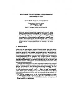
for modeling of sensors and actuators in the component model is given by the Framework for Supporting Hardware Devices [4] (described in details in Section III). However, current synthesis for ProCom does not take this framework into account. As opposed to all methods of treating hardware devices shown above, we propose a method that will enable explicit support for these devices and enable automatic synthesis of system-specific code. Such a synthesis method is currently not available in component models for ES. We aim to increase the reusability of components in the ES domain and provide more flexibility in system development. As a demonstrator of our approach we have implemented our hardware-specific code synthesis in the context of the ProCom component model. III. OVERVIEW OF THE H ARDWARE D EVICE S PECIFICATION F RAMEWORK To enable an effective code synthesis and efficient code reuse for hardware devices, we have developed a Hardware Device Specification Framework. The purpose of the framework is to allow explicit inclusion of hardware devices, such as sensors and actuators, into component models for embedded systems. In the framework, hardware devices are presented as software components, while leaving the components free of device- and platform-specific information. It then enables specification of device- and platform-specific information, and provides a way to associate it with software components. The part of the framework metamodel relevant for this work is shown in Figure 1. The framework includes three layers: software layer, hardware layer and mapping layer. The software layer includes device components, which represent hardware devices as software components, excluding any device- or platform-specific information. The lowest, hardware layer, contains information about hardware devices, the platform and how the two are connected. The mapping layer enables creating connections between hardware specific and hardware-independent layers. In the subsections below we provide a detailed description of each layer. A. Software layer In the software layer, the interaction of software components with hardware devices is represented by device components and their instances (context-specific representatives). Device components provide the same component interface and abide the same execution semantics as all other software components. Both types of components are treated the same during design – they can be used equivalently. But opposed to the ”pure” software components, which implement their functionality by code, device components do not implement any functionality, but serve as connection points to which we can associate device-specific functionality. Their functionality is defined once the component is mapped to a hardware
564
ICSEA 2012 : The Seventh International Conference on Software Engineering Advances
device (as described in Section III-C). However, they are in no way dependent on a specific hardware device or how the device is connected to the platform. B. Hardware layer The actual interaction with hardware devices is specified in the hardware layer. It is encapsulated in entities called IOs and hardware devices, and also defined by IO allocation. Input and output elements (e.g. pins or ports) of the platform are represented by IOs. An IO provides all information needed to communicate through the input or output it represents. IOs are reusable across different systems. Each IO references an IO type. IO types are abstract entities which define functionality that an IO of that type must provide, along with the data types and structures used. A hardware device model element represents a physical sensor or actuator and includes all information that is specific to that sensor or actuator. However, it does not cover the information describing how the device is connected to the underlying platform. Each hardware device entity refers to one software component from the software layer, indicating which functionality it can provide. It also defines the type of IO it requires from the platform. As with IOs, we can also reuse hardware device entities. Similar to device components in the software layer, hardware devices also have their context-specific instances. Hardware devices contain one or more required IO element. Required IOs represent platform IOs that the actual
Software layer Device Component
Instance of 1..1
Component Mapping
Hardware layer Hardware Device
Target HWD Target Req. IO 1..1
1..1
IO Allocation Target IO
Instance of 1..1
1..1
Hardware Device Instance
Instance of 1..1
1..1
IO Type
Figure 1.
Target HWD
1..*
Required IO IO Type
1..1
Target Component
Mapping layer
Required IO
Device Component Instance
1..1
IO
Metamodel of the Hardware Devices Specification Framework.
Copyright (c) IARIA, 2012.
ISBN: 978-1-61208-230-1
physical sensor or actuator needs for communication. The types of these IOs are specified by referring to IO type elements. To create an actual system, we need to create IO allocations, i.e. to describe an IO allocation to reflect the current system configuration. C. Mapping layer The mapping layer allows us to create connections (mappings) between elements of the software and hardware layers. When we map a device component from the software layer to a hardware device from the hardware layer, we denote that the hardware device will be used as the realization for the device. Once such a mapping is defined we can utilize any information defined for the hardware device entity (and IO, if IO allocation is present) in the software layer. IV. C ODE S YNTHESIS The code synthesis is based on two principles – (a) separation of reusable code from the device- and platformspecific code and (b) automatic generation of device- and platform-specific code based on a system model that includes software and hardware components. We achieve this by first defining a way to specify system-independent and reusable code elements for device- and platform-specific functionality. Besides just functionality, reusable code elements also define interfaces for communication. Using a system model we then generate code that utilizes these interfaces to combine the software component code with device- and platform specific functionality resulting in a system-specific deployable solution. An overview of the synthesis process is given in Figure 2. Our approach consists of two categories of code: (a) input code elements which will be used as input to the synthesis, and (b) generated code that connects the input elements. An overview of all the code elements used in synthesis and the relations between them is given in Figure 3. These code elements are described in detail below. A. Synthesis Input Code Definition In the implementation of the solution we used the C programming language, as C is the language still mostly used to develop embedded systems. However, the principles used in this solution are not limited to C. They can easily be implemented in other programming languages. The input code is separated into elements that are as independent as possible from each other, making them fit for reuse. These four elements are: • device component code – platform, device and system independent code, • IO type code – code that describes capabilities for different IOs, • IO code – platform-specific code that implements IO functionality,
565
ICSEA 2012 : The Seventh International Conference on Software Engineering Advances
hardware device code – device specific code that implements device functionality. Besides defining parts of functionality, these elements also define structures and function signatures that will be used as communication interfaces. Coupling between them is loose: all function calls are performed using function pointers, which are assigned during the mapping and allocation phase. All these elements are system independent and can be reused in different systems or platform configurations. 1) Device component code: As we want to place deviceand platform-specific code outside software components, device component code does not provide any functionality. Instead, it only provides a way to make calls to devicespecific functions once the system model is defined. Device component code consists of a structure that includes: (a) definitions of zero or more variables that will be used to communicate data to and from a hardware device and (b) pointers that will be used to map and allocate appropriate device- and platform-specific functionality. Allocation data (described in Section IV-A2 and Section IV-A4) will be assigned to a void pointer. For mapping we use a function pointer to an entry function that will implement device functionality. This function receives the device component structure, and with it means to assign or read data and use appropriate platform IO functions. We describe how these pointers are assigned in Section IV-B. 2) IO type code: In the IO type code we define an IO interface structure that will be used to communicate •
Reusable Models and Code Component Interface Code
DeviceSpecific Code
IO Definition Code
PlatformSpecific Code
Device Component
Hardware Device
IO Type
IO
System Model
IO Allocation
Mapping
through an IO. This interface structure contains pointers (signatures) for one or more functions that will be used for the communication. The number of functions can differ for different kinds of IOs. Some of the functions can also be used for configuration of the communication channel, rather than for the communication itself. The code can also contain definitions of data structures that will be used as arguments to functions in case the arguments are not basic C types. An instance of the interface structure will be used to allocate Hardware Devices to IOs (described in Section IV-B1). 3) IO code: Code defined for IOs provides the platform specific implementation for functions defined in the interface structure of the IO type code. The IO code of each physical platform can be comprised of many C source files, all of which implement communication just for one specific IO. Separation of IO code into different files allows us to use the minimum amount of platform-specific code once we synthesize the code for the whole system. For an IO source file to be valid it must implement all the functions defined in the interface structure of the IO type. Also, each IO code definition must define an IO interface assignment function that receives an IO interface structure and assigns function implementations to the function pointers of the structure. How these functions are used for the actual allocation is described in Section IV-B1). 4) Hardware device code: The main purpose of hardware device code is to provide an implementation of communication for a specific sensor or actuator. This includes the protocol used to communicate with the device, possible adaptation of data and calls to IO functions. To provide device-specific implementation for a device component, the hardware device source code must implement a function which has a signature matching the signature of the component entry function. Code for each hardware device also includes an IO allocation structure that contains instances of IO interface structures for each IO type that the device requires. An instance of this structure will be referenced by a pointer in the device component structure, and can be used for making platform-specific IO function calls. B. Generated code
Generated code IO Allocation Code
Mapping Code
Synthesis result Component Interface Code
DeviceSpecific Code
Mapping Code
IO Allocation Code
IO Definition Code
PlatformSpecific Code
Legend: Function calls References
Figure 2.
Code input or output
Code Element
Model element
Overview of the synthesis process and results.
Copyright (c) IARIA, 2012.
ISBN: 978-1-61208-230-1
Using a system model, which is based on the previously described framework, we are able to generate code that implements the functionality of the system. The code we generate creates connections between the various input code elements we defined, using their interfaces. Code generation is divided into two phases: generation of IO allocation code and generation of device mapping code. Listing 5 shows mapping and allocation code generated for our example. 1) IO allocation code: The IO allocation code provides connections between instances of device components and platform IOs. It enables devices to make function calls to platform IO functions, abstracting away platform specifics.
566
ICSEA 2012 : The Seventh International Conference on Software Engineering Advances
Device Component Code
Device Component Struct Data Variables [0..*] Device Allocation Pointer Entry-Function Pointer
Allocation Code
Mapping Code
Device Component Struct Instance
IO Allocation Struct Instance
Allocation Mapping Function
Allocation Function IO Allocation Function Call [1..*]
Entry-Function Mapping Function
Hardware Device Code Entry-Function Implementation
IO Allocation Struct IO Interface Structure Instance [1..*]
IO Type Code Data Definition Struct [0..*] Variable Definition [1..*] IO Interface Struct IO Function Pointer Definition [1..*]
IO Code IO Interface Assignment Function IO Function Assignment [1..*]
IO Function Implementation
Legend: Implementation or instantiation
Value assignment
Reference
Figure 3. Code elements in our synthesis approach and relations between them. For the elements that can occur multiple times, multiplicity is shown in square brackets.
To generate IO allocation code we use hardware device elements, IO elements and IO allocation elements from the system model, and their respective input code elements. First, we traverse the model and for each device referenced by IO allocation elements we define an instance of the IO allocation structure defined by the input code of the hardware device, giving each instance of the structure a unique name. Even if a device requires more than one IO for its functionality, only one such structure is created, as the structure contains variables for all required IOs. After that we are able to generate an allocation function that will assign appropriate IO functions to function pointers defined in the IO allocation structures. In this function, for every IO allocation element we create a function call to the IO interface assignment function defined by the input code of the referenced IO element. As an argument, we provide the IO interface structure instance defined in the previous step of IO allocation code generation. The function call then assigns the correct platform function calls defined by the referenced IO to the IO allocation structure generated for the referenced hardware device. One IO interface assignment function call is created for each required IO. 2) Mapping code: Device- and platform-specific functionality is provided to software components by generation of mapping code. For this we use the device component elements, hardware device elements and device component mapping elements of the system model. As a first phase of mapping code generation we create instances of device component data structures which will
Copyright (c) IARIA, 2012.
ISBN: 978-1-61208-230-1
hold mapping data. The instance name is based on the unique ID of the component instance. In the next phase we generate allocation mapping code. This code binds IO allocations generated during IO allocation code generation to device component instances. For each device component mapping we create a line of code that assigns an IO allocation structure which represents the instance of device component referenced by mapping (generated as part of IO allocation code) to the IO allocation pointer of device component data structure. The final part of the mapping code is the entry function mapping. This code connects device software components with device entry functions which implement device-specific functionality. We achieve this by generating code that assigns an entry function of the device referenced by the mapping to the entry function pointer of the data structure of the device component the mapping is targeting. V. I MPLEMENTATION For the purpose of evaluation we have implemented our approach in the context of the ProCom component model. The implementation was done using Java. Our automated synthesis is included in PRIDE [16] – an Eclipse based IDE for ProCom. It leverages Eclipse Modeling Framework for model traversal and Java for code generation. Standard ProCom components are implemented by a single C entry function that executes when the component is triggered to perform its functionality. This function receives a data structure that contains instance-specific component
567
ICSEA 2012 : The Seventh International Conference on Software Engineering Advances
data. We adapted these elements to align with our device component code. As a way to make function calls to the device-specific entry function, we have defined a standard entry function that all device components must implement. This entry function has only one line of code, which diverts the function call to the hardware specific entry function assigned to the entry function pointer of the component instance data structure.
6, and line 7 defines the pointer that will reference the device entry function. 1 2 3 4 5 6
7
VI. E XAMPLE We will demonstrate our approach on a real example using the GDM2004 LCD display module. In code listings shown for the example we have removed some parts of the code (e.g. ”include” instructions and use of unique IDs in naming) that are not relevant to show the principles of our solution. The example consists of a device component instance (DisplayComponent display) which maps to GDM2004 instance of the GDM2004Device hardware device. The GDM2004Device requires three IOs of type OneBitIO (named registerSelect, RW and enable), and one IO of type IO8BitPort (named data). These requirements are allocated to platforms IOs PA0, PA1, PA2 and PE. A model of the example is shown in Figure 4.
typedef struct DisplayComponent { int row; int column; char* text;
8
void * ioAllocation; // Pointer to IO allocation void (*entryFunction) (struct DisplayComponent*); // Pointer to device specific entry function } DisplayComponent; Listing 1.
B. IO type code The IO type code for our example is shown in Listing 2. On line 2 we can see a definition of the data structure that will be used to communicate configuration data for the port. The IO interface structure that defines function pointers for function used for communication is located at lines 8 to 12. 1 2 3 4
A. Device component code
5
In our example, code that defines the DisplayComponent device component can be seen in Listing 1. The device component structure begins at line 1. Lines 2 to 3 contain data variables that will be used for communication. The pointer that will reference allocation data is defined on line
7
// Data definition typedef struct { int isOutput; int isOpenDrain; } OneBitIO_configData;
6
8 9 10 11 12
// IO interface structure typedef struct { void (*writeData) (int); void (*readData) (int*); void (*configure) (OneBitIO_configData*); } OneBitIO; Listing 2.
instanceOf
DisplayComponent
Listing 3 shows the IO code for port PA0 of our example. From lines 2 to 12 we can see functions that implement port communication, which adhere to function signatures defined in the IO type interface structure. The IO interface assignment function, which assigns functions defined in lines 2 to 12 to an instance of IO type interface structure, is on lines 16 to 20.
targetComponent targetDevice
GDM2004Device
GDM2004 targetDevice
requiredIO
1
targetReq
targetReq
targetReq
registerSelect RW
enable
PA0 PA1
targetReq
data
2 3 4
6
PA2
7
8
PE
OneBitIO ioType
void PA0_readData(int* value) { RdPortI(PADR, &PADRShadow, value, 0); }
9
ioType
IO8BitPort
// START functions implementing IO void PA0_writeData(int value) { WrPortI(PADR, &PADRShadow, value, 0); }
5
10
ioType
Example of IO type code.
C. IO code
display
instanceOf
Display component code.
11
ioType 12 13
void PA0_configure(OneBitIO_configData* data) { WrPortI(PADDR, &PADDRShadow, data-> isOutput, 0); } // END functions implementing IO
14 15
Figure 4.
Model of the GDM2004 example.
Copyright (c) IARIA, 2012.
ISBN: 978-1-61208-230-1
16
// Assigning functions for allocation void allocate_PA0(OneBitIO* allocation) {
568
ICSEA 2012 : The Seventh International Conference on Software Engineering Advances
allocation->writeData = &PA0_writeData; allocation->readData = &PA0_readData; allocation->configure = &PA0_configure;
17 18 19 20
} Listing 3.
Example of IO code.
1) Hardware device code: Hardware device code that implements functionality for the GDM2004Device defined in our example is given in Listing 4. The IO allocation structure for GDM2004Device begins on line 2. It contains one IO interface structure for each required IO, on lines 3 to 6. The device entry function definition can be seen on lines 10 to 18. How the allocated IO interface structures are used can be seen in the GDM2004PrintChar function which starts on line 26. 1 2 3 4 5 6 7
// Structure for IO allocation typedef struct GDM2004_allocation{ OneBitIO registerSelect; OneBitIO rw; OneBitIO enable; IO8bitPort data; } GDM2004_allocation;
8 9 10
11 12
// Implementation of the entry function void entry_GDM2004(DisplayComponent* instanceData) { int i; GDM2004_allocation* alloc = ( GDM2004_allocation*) instanceData-> ioAllocation;
13
GDM2004SetPosition(instanceData->column, instanceData->row, alloc); for (i=0; i < strlen(instanceData->text; ++i) { GDM2004PrintChar(instanceData->text[i], alloc); }
14
15
16
17 18
}
19 20
21 22 23 24
void GDM2004SetPosition(int column, int row , GDM2004_allocation* alloc) { /* Implementation skipped */ }
25 26
27 28 29 30 31 32 33 34
void GDM2004PrintChar(char c, GDM2004_allocation* alloc) { alloc->registerSelect.writeData(1); alloc->rw.writeData(0); alloc->enable.writeData(1); Delay_60usec(); alloc->data.writeData(c); alloc->enable.writeData(0); Delay_60usec(); } Listing 4.
GDM2004 HardwareDevice code.
D. IO allocation and mapping code Listing 5 shows the IO allocation structure created for the GDM2004 instance of GDM2004Device on line 2. The allocation function shown on lines 3 to 8 contains function calls
Copyright (c) IARIA, 2012.
ISBN: 978-1-61208-230-1
to IO allocation functions defined by IO for registerSelect, RW, enable and data required IOs of the GDM2004Device. Line 12 of Listing 5 contains an instance of the device component data structure for DisplayComponent. On line 14 we can find the allocation mapping function, in which the IO allocation structure instance from line 2 is assigned to the IO allocation pointer of the DisplayComponent data structure. The entry function mapping is shown on lines 18 to 20, where we assign the entry function defined by GDM2004Device to the entry function pointer of the DisplayComponent data structure. 1 2 3 4 5 6 7 8 9
// ***** START ALLOCATION GDM2004_allocation display; void doIOAllocation() { allocate_PA0(&(display.registerSelect)); allocate_PA1(&(display.rw)); allocate_PA2(&(display.enable)); allocate_PE(&(display.data)); } // ***** END ALLOCATION
10 11 12
// ***** START MAPPING DisplayComponent displayComponent;
13 14 15 16
void doAllocationMapping() { displayComponent.ioAllocation = &display; }
17 18 19
20 21
void doEntryMapping() { displayComponent.entryFunction = & entry_GDM2004; } // ***** END MAPPING Listing 5.
Example of generated mapping and allocation code.
VII. C ONCLUSION In this paper, we have presented an approach to code synthesis for embedded systems which utilizes a system model to generate hardware-specific code. The system model we use describes software components, hardware devices (i.e. sensors and actuators) and inputs and outputs of the platform, and connections between all these elements. We provide strict definitions of how to specify interface and implementation code for the model elements in order to get reusable units of code that we use as inputs for our synthesis. During the synthesis process we generate gluecode that connects these reusable code elements to provide the functionality defined by the system model. Compared to having hardware-specific code hard-coded inside software components, in our approach software components are not directly dependant on hardware devices or how the devices are connected to the platform. The result of this is more efficient code reuse. The approach presented in this paper provides a level of abstraction over hardware devices and the platform. It also separates the concerns of hardware-independent software development, hardware-specific software development and system integration. On a higher level, software systems
569
ICSEA 2012 : The Seventh International Conference on Software Engineering Advances
can be developed without knowing the specifics of the underlying platform. On the other hand, low level hardwarespecific functionality can be implemented independently of the rest of the system. Both levels can in the end be used as black-boxes and integrated into systems with no knowledge of their internals. ACKNOWLEDGMENT This work was supported by the Swedish Foundation for Strategic Research project RALF3 and the Swedish Research Council project CONTESSE (2010-4276). We would like to thank Jan Carlson for providing valuable comments on the paper. R EFERENCES [1] I. Crnkovic and M. Larsson, Building Reliable ComponentBased Software Systems. Norwood, MA, USA: Artech House, Inc., 2002. [2] C. Atkinson, C. Bunse, C. Peper, and H.-G. Gross, “Component-based software development for embedded systems an introduction,” in Component-Based Software Development for Embedded Systems, ser. Lecture Notes in Computer Science, C. Atkinson, C. Bunse, H.-G. Gross, and C. Peper, Eds. Springer Berlin / Heidelberg, vol. 3778, pp. 1–7. [3] L. Lednicki, “Support for hardware devices in component models for embedded systems,” in International Doctoral Symposium on Software Engineering and Advanced Applications, August 2011. ˇ [4] L. Lednicki, J. Feljan, J. Carlson, and M. Zagar, “Adding support for hardware devices to component models for embedded systems,” in ICSEA 2011, The Sixth International Conference on Software Engineering Advances, 2011, pp. 149–154. [5] S. Sentilles, A. Vulgarakis, T. Bureˇs, J. Carlson, and I. Crnkovi´c, “A component model for control-intensive distributed embedded systems,” in Component-Based Software Engineering, ser. Lecture Notes in Computer Science, M. Chaudron, C. Szyperski, and R. Reussner, Eds. Springer Berlin / Heidelberg, vol. 5282, pp. 310–317. ˇ [6] L. Lednicki, I. Crnkovi´c, and M. Zagar, “Towards automatic synthesis of hardware-specific code in component-based embedded systems,” in SEAA 2012,38th Euromicro Conference on Software Engineering and Advanced Applications, September 2012.
Copyright (c) IARIA, 2012.
ISBN: 978-1-61208-230-1
[7] S. Burmester, H. Giese, and W. Schaefer, “Model-driven architecture for hard real-time systems - from platform independent models to code,” in Model Driven Architecture Foundations and Applications, ser. Lecture Notes in Computer Science, A. Hartman and D. Kreische, Eds. Springer Berlin, Heidelberg, vol. 3748, pp. 25–40. [8] J. Hugues, B. Zalila, L. Pautet, and F. Kordon, “From the prototype to the final embedded system using the ocarina aadl tool suite,” ACM Trans. Embed. Comput. Syst., vol. 7, no. 4, pp. 42:1–42:25, Aug. 2008. [9] A. Rodrigues, G. Fr´ed´eric, and J. Dekeyser, “An mde approach for automatic code generation from marte to opencl,” INRIA Lille-RR-7525 [Online]. Available: http://hal. inria. fr/inria-00563411/PDF/RR-7525. pdf/, Tech. Rep. [10] J. Feljan, L. Lednicki, J. Maras, A. Petriˇci´c, and I. Crnkovi´c, “Classification and survey of component models,” M¨alardalen University, Technical Report ISSN 1404-3041 ISRN MDHMRTC-242/2009-1-SE, December 2009. [11] “The SAVE approach to component-based development of vehicular systems,” Journal of Systems and Software, vol. 80, no. 5, pp. 655 – 667, 2007. [12] K. Hanninen, J. Maki-Turja, M. Nolin, M. Lindberg, J. Lundback, and K.-L. Lundback, “The Rubus component model for resource constrained real-time systems,” in Industrial Embedded Systems, 2008. SIES 2008. International Symposium on, june 2008, pp. 177 –183. [13] H. Heinecke, W. Damm, B. Josko, A. Metzner, H. Kopetz, A. Sangiovanni-Vincentelli, and M. Di Natale, “Software components for reliable automotive systems,” in Proceedings of the conference on Design, automation and test in Europe, ser. DATE ’08, 2008, pp. 549–554. [14] E. Borde and J. Carlson, “Automatic Synthesis and Adaption of Gray-Box Components for Embedded Systems – Reuse vs. Optimization,” in Computer Software and Applications Conference Workshops (COMPSACW), 2011 IEEE 35th Annual, july 2011, pp. 224–229. [15] ——, “Towards verified synthesis of ProCom, a component model for real-time embedded systems,” in Proceedings of the 14th international ACM Sigsoft symposium on Component based software engineering, ser. CBSE ’11, 2011, pp. 129– 138. [16] E. Borde, J. Carlson, J. Feljan, L. Lednicki, T. L´evˆeque, J. Maras, A. Petricic, and S. Sentilles, “Pride - an environment for component-based development of distributed realtime embedded systems,” in Proceedings of the 2011 Ninth Working IEEE/IFIP Conference on Software Architecture, ser. WICSA ’11, 2011, pp. 351–354.
570