Towards Automatic Synthesis of Hardware-Specific Code in Component-based Embedded Systems Luka Lednicki, Ivica Crnkovi´c M¨alardalen Real-Time Research Centre M¨alardalen University V¨aster˚as, Sweden Email: {luka.lednicki,ivica.crnkovic}@mdh.se
Abstract—Most component models currently in use do not try to provide extensive support for dealing with hardware devices like sensors and actuator. Lack of such support means that software components and subsystems often include deviceand platform-specific code, limiting our ability to reuse them and forcing us to deal with specifics of underlying hardware in high-level software models. In this paper we propose a solution that would enable automatic generation of devicespecific code. We remove device- and platform-specific code outside of software components and specifying it as reusable units. Based on a system model we then generate glue-code that binds this reusable units of code to each other and to the software components, resulting in a system-specific solution. Keywords-component-based development; code synthesis; hardware devices; sensors; actuators; embedded systems
I. I NTRODUCTION Component-based development (CBD) is one of the approaches suggested to alleviate the constant rise in the complexity of embedded systems (ES) [1], [2]. One of the aspects that is crucial for use of CBD in embedded systems is communication with hardware devices such as sensors and actuators. However, inclusion of hardware device-specific elements in software components decreases the components’ reusability [3]; If a component includes device-specific code, or code that is specific to a platform, the component cannot be efficiently reused in case of changes of the underlying hardware. Therefore, by making software functionality independent from a specific hardware configuration, and by providing means to automatically generate the hardwarespecific code we can make reuse of code in embedded systems more efficient. Synthesis of hardware-specific code has been explored model-driven engineering in general in model-driven approach [4], and in specific modeling languages such as AADL [5] or MARTE [6]. However, automatic generation of glue code for connecting device-specific code has not been established in component models for embedded systems. In most component models used in academia hardware-specific code is externalized – not present in software components and put outside the scope of component model. One example of externalized devices is SaveCCM [7]. Component models
ˇ Mario Zagar Faculty of Electrical Engineering and Computing University of Zagreb Zagreb, Croatia Email:
[email protected]
targeting industry provide support for hardware devices, but this support is mostly implicit, which means that the hardware-specific code is hard-coded in the software component code. An example of such support for hardware devices can be found in Rubus [8]. One of the most extensive support for hardware devices is given by AUTOSAR [9] in which interaction with hardware devices is done using specialized and hardware specific sensor/actuator components. In this paper we present a novel way to provide code synthesis for component software in embedded system domain, which allows a transparent use of hardware devices in software models. Our goal is to automatically generate systemspecific code for interaction with hardware devices while reusing predefined device- and platform-specific. We do this by first separating software component code, device-specific code and platform-specific code, while strictly defining their content and interfaces they can use for to communicate with each other. By this we get system-independent, reusable units of code. We then use a model that describes software components, hardware devices and the deployment platform to automatically generate-glue code that connects the mentioned code parts into a deployable system. Our approach is based on the framework for handling interaction of software components with hardware devices that we proposed in [10]. The rest of the paper is organized as follows. In section II we present the framework we use for specification of hardware devices. section III describes our approach to hardwarespecific code synthesis and gives an example of the synthesis implementation. Finally, section IV concludes the paper. II. OVERVIEW OF THE H ARDWARE D EVICE S PECIFICATION F RAMEWORK Purpose of the Hardware Device Specification Framework which allows explicit inclusion of hardware devices, such as sensors and actuators, into component models for embedded systems. In the framework, hardware devices are presented as software components, while leaving the components free of device- and platform-specific information. It then enables specification of device- and platform-specific information, and provides a way to associate it with software components.
Software layer Device Component
Instance of 1..1
Component Mapping
Hardware layer Hardware Device
Target HWD Target Req. IO 1..1
1..1
IO Allocation Target IO
Instance of 1..1
1..1
Hardware Device Instance
Instance of 1..1
1..1
IO Type
Figure 1.
Target HWD
1..*
Required IO IO Type
1..1
Target Component
Mapping layer
Required IO
Device Component Instance
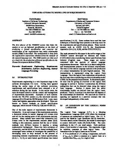
Hardware devices contain one or more required IO elements. Required IOs represent platform IOs that the actual physical sensor or actuator need for communication. Types of these IOs are specified by referencing IO type elements. When we want to create an actual system, we need to create IO allocations: describe how the devices are connected to the platform. IO allocations create connections between IOs, hardware device instances and required IOs. Mapping layer allows us to create connections (mappings) between elements of software and hardware layers. When we map a device component form the software layer to hardware device from the hardware layer, we denote that the hardware device will be used as the realization for the device.
1..1
IO
Metamodel of the Hardware Devices Specification Framework.
The part of the framework metamodel relevant for this work is shown in Figure 1. The framework includes three layers: software layer, hardware layer and mapping layer. In software layer, interaction of software components with hardware devices is represented by device components and their instances (context-specific representatives). Device components provide same component interface and abide same execution semantics as all other software components. Both types of components are treated the same during design – they can be used equivalently. But opposed to ”pure” software components, which implement their functionality by code, device components do not implement any functionality. Their functionality is defined once the component is mapped to a hardware device. Hardware layer contains information about hardware devices, the platform and how the two are connected. Input and output elements (e.g. pins or ports) of the platform are represented by IOs. Each IO references an IO type. IO types are abstract entities which define functionality that IOs must provide, along with the data types or structures used. A hardware device model element represents a physical sensor or actuator. They include all information that is specific to that sensor or actuator. Each hardware device entity refers one software components from the software layer, indicating which functionality it can provide. It also defines the type of IO it requires from the platform. Similar to device components in the software layer, hardware devices also have their context-specific instances.
III. C ODE S YNTHESIS In the framework described above we define a new approach to code synthesis: We first define a way to specify system-independent and reusable code elements for deviceand platform-specific functionality. Besides just functionality, reusable code elements also define interfaces for communication between them. Using a system model we then generate code that utilizes these interfaces to combine the software component code with device- and platform specific functionality resulting in a system-specific deployable solution. An overview of the synthesis process and the result is given in Figure 2.
Reusable Models and Code Component Interface Code
DeviceSpecific Code
IO Definition Code
PlatformSpecific Code
Device Component
Hardware Device
IO Type
IO
System Model Mapping
IO Allocation
Mapping Code
IO Allocation Code
Generated code
Synthesis result Component Interface Code
Mapping Code
DeviceSpecific Code
IO Allocation Code
IO Definition Code
PlatformSpecific Code
Legend: Function calls References
Figure 2.
Code input or output
Code Element
Model element
Overview of the synthesis process and results.
Device Component Code
Device Component Data Device Allocation Storage Entry-Function Interface
Allocation Code
Mapping Code
IO Allocation Instance
Device Component Instance
IO Allocation Assignment [1..*]
Allocation Mapping Hardware Device Code Entry-Function Implementation
IO Allocation Data IO Interface Instance [1..*]
Entry-Function Mapping
IO Type Code
Data Definition [0..*] Variable Definition [1..*]
IO Code
IO Interface
IO Interface Implementation
Legend: Implementation or instantiation
Value assignment
Reference
Figure 3. Code elements in our synthesis approach and relations between them. For the elements that can occur multiple times multiplicity is shown in square brackets.
Our approach consists of two groups of code: (a) input code elements which will be used as input to the synthesis, and (b) generated code that connects the input elements. An overview of all the code elements used in the syntesis process and relations between them is given in Figure 3. These code elements are described in details below. A. Synthesis Input Code Definition Input code is separate into elements in a way that the elements are independent as much as possible from each other, making them fit for reuse. These four elements are: • device component code – platform, device and system independent code, • IO type code – code that describes capabilities for different IOs, • IO code – platform-specific code that implements IO functionality, • hardware device code – device specific code that implements device functionality. All these elements are system-independent and loosely coupled, and can be reused in different systems or different platform configurations. Next, we will give a detailed description of the input code elements. 1) Device Component Code: As we want to place deviceand platform-specific code out of software components, device component code does not provide any concrete functionality. Instead, it only provides a way to make calls to device-specific functions once the system model is defined. This is done by providing storage for allocation data for an
instance of a device component and storage for a reference to code implementing communication to the device. We describe how these two are assigned in subsection III-B. When device component executes it just delegates execution call to the implementation code, passing also the allocation data. 2) IO Type Code: In IO type code we define an interface that will be used to communicate through an particular IO type. Functions defined in the interface can be used for data input and output, but also for configuration of the communication channel. IO code can also contain definitions of data structures that will be used as arguments to IO functions. 3) IO Code: Code defined for IOs provides platform specific implementation for interfaces defined in the IO type code. For one platform, we will have to provide separate IO code for all its inputs and outputs. This code will then be connected to hardware device code (described in the next subsection) during allocation code generation (described in subsubsection III-B1). 4) Hardware Device Code: Main purpose of hardware device code is to provide implementation of functionality for a specific sensor or actuator. This includes protocol used to communicate to the device, possible adaptation of data and calls to one or more IO functions. Hardware device code must implement an entry function which will be referenced by device component and called when device component is executed. Also, this code will define a data structure that will be used to store information about allocation of a hardware
device instance to platforms IOs. B. Generated code Using a system model, which is based on the previously described framework, we are able to generate code that implements functionality of the system. The code we generate creates connection between various elements of input code elements using the interfaces they define. Code generation is divided into two phases: generation of IO allocation code and generation of device mapping code. 1) IO Allocation Code: IO allocation code provides connections between instances of device components and platform IOs. It enables devices to make function calls to platform IO functions, abstracting away platform specifics. To generate IO allocation code we use hardware device elements, IO elements and IO allocation elements from the system model, and their respective input code elements. First, we traverse the model for each device referenced by IO allocation and create instances of IO allocation data structures defined by by the hardware device code. After that, using IO allocation model elements, we generate code that will assign appropriate IO functions to these data structure instances. 2) Mapping Code: Device- and platform-specific functionality is provided to software components by generation of mapping code. As first phase of mapping code generation we create instances of device component data structures which will hold mapping data. In the next phase we generate allocation mapping code. This code binds IO allocations generated during IO allocation code generation to device component instances. Final part mapping code generation is entry function mapping. Entry function mapping code connects device software components with device entry functions which implement device-specific functionality. IV. C ONCLUSION In this paper we have presented how automatic generation of hardware specific code can be used in component models for embedded systems. Our approach is based on (a) giving strict definitions for how to specify device- and platformspecific code in a way that will make it reusable, and (b) automatic generation of glue code (based on the system model) that will bind the reusable code units into a systemspecific solution. By utilizing this approach we can increase reusability of code used for communication with sensors and actuators. The new level of abstraction over such hardware devices and the platform allows for separation of development of highlevel software functionality from the low- level hardwarespecific functionality. ACKNOWLEDGMENT This work was supported by the Swedish Foundation for Strategic Research project RALF3 and the Swedish Research Council project CONTESSE (2010-4276).
R EFERENCES [1] I. Crnkovic and M. Larsson, Building Reliable ComponentBased Software Systems. Norwood, MA, USA: Artech House, Inc., 2002. [2] C. Atkinson, C. Bunse, C. Peper, and H.-G. Gross, “Component-based software development for embedded systems an introduction,” in Component-Based Software Development for Embedded Systems, ser. Lecture Notes in Computer Science, C. Atkinson, C. Bunse, H.-G. Gross, and C. Peper, Eds. Springer Berlin / Heidelberg, 2005, vol. 3778, pp. 1–7. [Online]. Available: http: //dx.doi.org/10.1007/11591962 1 [3] L. Lednicki, “Support for hardware devices in component models for embedded systems,” in International Doctoral Symposium on Software Engineering and Advanced Applications, August 2011. [Online]. Available: http: //www.mrtc.mdh.se/index.php?choice=publications&id=2626 [4] S. Burmester, H. Giese, and W. Schaefer, “Model-driven architecture for hard real-time systems - from platform independent models to code,” in Model Driven Architecture - Foundations and Applications, ser. Lecture Notes in Computer Science, A. Hartman and D. Kreische, Eds. Springer Berlin, Heidelberg, 2005, vol. 3748, pp. 25–40. [Online]. Available: http://dx.doi.org/10.1007/11581741 4 [5] J. Hugues, B. Zalila, L. Pautet, and F. Kordon, “From the prototype to the final embedded system using the ocarina aadl tool suite,” ACM Trans. Embed. Comput. Syst., vol. 7, no. 4, pp. 42:1–42:25, Aug. 2008. [Online]. Available: http://doi.acm.org/10.1145/1376804.1376810 [6] A. Rodrigues, G. Fr´ed´eric, and J. Dekeyser, “An mde approach for automatic code generation from marte to opencl,” INRIA Lille-RR-7525 [Online]. Available: http://hal. inria. fr/inria-00563411/PDF/RR-7525. pdf/, Tech. Rep. ˚ [7] M. Akerholm, J. Carlson, J. Fredriksson, H. Hansson, J. Hakansson, A. M¨oller, P. Pettersson, and M. Tivoli, “The SAVE approach to component-based development of vehicular systems,” Journal of Systems and Software, vol. 80, no. 5, pp. 655 – 667, 2007. [Online]. Available: http://www. sciencedirect.com/science/article/pii/S0164121206002226 [8] K. Hanninen, J. Maki-Turja, M. Nolin, M. Lindberg, J. Lundback, and K.-L. Lundback, “The Rubus component model for resource constrained real-time systems,” in Industrial Embedded Systems, 2008. SIES 2008. International Symposium on, june 2008, pp. 177 –183. [9] H. Heinecke, W. Damm, B. Josko, A. Metzner, H. Kopetz, A. Sangiovanni-Vincentelli, and M. Di Natale, “Software components for reliable automotive systems,” in Proceedings of the conference on Design, automation and test in Europe, ser. DATE ’08. New York, NY, USA: ACM, 2008, pp. 549–554. [Online]. Available: http://doi.acm.org/10.1145/ 1403375.1403508 ˇ [10] L. Lednicki, J. Feljan, J. Carlson, and M. Zagar, “Adding support for hardware devices to component models for embedded systems,” in ICSEA 2011, The Sixth International Conference on Software Engineering Advances, 2011, pp. 149–154.