modern software development paradigms (like object-orientation, modularization, design patterns, etc.) into a comprehensive and widely accepted visual ...
Automatic Transformation of UML Models for System Verification D´aniel Varr´o, Szilvia Gyapay, and Andr´as Pataricza Budapest University of Technology and Economics Department of Measurement and Information Systems 1111 Budapest, Hungary, P´azm´any P. st. 1/D. IT building B.420. Contact person: Andr´as Pataricza Phone: +36-1-463-3595 Fax:+36-1-463-4112 pataric,varro @mit.bme.hu �
�
Abstract The design of complex, dependable systems requires a precise formal verification of design decisions during the system modelling phase. For that reason, the mathematical models of various formal verification tools are planned to be automatically derived from the system model described by UML–diagrams. In the current paper, a general framework for an automated model transformation system is outlined providing a uniform formal description method of such transformations by applying the powerful computational paradigm of graph transformation. Keywords: formal verification, UML, model transformation.
1 Introduction 1.1
Formal Methods in UML Design
During the recent years, UML has become the standard of object–oriented modelling. It integrates the modern software development paradigms (like object-orientation, modularization, design patterns, etc.) into a comprehensive and widely accepted visual language, moreover, it provides a complete methodology for designing a large scale of IT systems. However, system analysts have to face certain difficulties when utilizing UML in the design process of complex, dependable systems (e.g. for safety critical applications) as an effective design of such systems surely necessitates a mathematically precise formal verification at each phase of modelling. Formal methods serve as a rigorous mathematical platform for verifying and analyzing such computer systems. For many years, they have been a topic of research with valuable academic results [1], however, their industrial utilization (despite their vital necessity) is still limited to specialized fields. The use of formal verification tools (like model checkers SPIN [7] or PVS [11]) in IT system design is hindered by a gap between practice–oriented CASE tools and sophisticated mathematical tools. – On the one hand, system engineers usually show no proper mathematical skills required for applying formal verification techniques in the software design process. – On the other hand, even if a formal analysis is carried out, the consistency of the manually created mathematical model and the original system is not assured, moreover, the interpretation of analysis results, thus, the re–projection of the mathematical analysis results to the designated system is also problematical. The aim of our ongoing research is to provide provenly correct and complete, automated transformations between UML–based system models and formal mathematical verification tools for an effective software analysis and design.[14] �
This work was supported by the Hungarian National Scientific Foundation Grant OTKA T030804
WTUML 2001: Workshop on Transformations in UML pp. 123–127, April 7th, 2001, Genova, Italy 1.2
Mathematical Model Transformation
The step generating the input language of a target mathematical tool from the UML model of the system is denoted as mathematical model transformation. The inverse direction of model transformation (referred as back–annotation) is of immense practical importance as well when some problems (e.g. a deadlock) are detected during the mathematical analysis. After an automated back–annotation these problems can be visualized in the the same UML system model allowing the designer to fix conceptual bugs within his well–known UML environment. Several semi-formal transformation algorithms have been designed and implemented for different purposes (such as formal verification of functional properties [8] or quantitative analysis of dependability attributes [2,3]). Unfortunately, this conventional way of model transformation lacked a uniform and precise description of transformation algorithms resulting in hand–written and rather ad hoc implementations (inconvenient for implementing complex transformations). Moreover, any formal proof of correctness and completeness aiming to verify these transformation scripts is almost impossible, thus their uncertain quality remains a quality bottleneck of the entire transformation based verification approach. Thus, a model transformation system (avoiding these drawbacks) must fulfil at least the following user requirements. – A large number of model transformations are planned to be designed to perform dependability analysis in various application domains ranging from early evaluation methods based on Petri nets to model checking techniques using temporal logic as underlying mathematical model. – “Mathematical” model transformations are not only designed by mathematicians but system engineers as well. Thus, these transformations must be defined by a visual, easy to understood formalism. – The specification of a model transformation should be given in mathematically precise, unambiguous form.
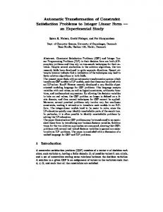
2 A Visual Automated Model Transformation System The process of model transformation is characterized by a model analysis round-trip illustrated in Fig. 1. Typically, a system designer and a transformation designer participates in such a round-trip with the following roles. – A transformation designer specifies model transformations from UML to various mathematical models (like e.g. Petri nets, temporal logic). From his specification, a transformation algorithm is generated at compile time. – A system analyst designs complex systems using UML as modelling language. During the software life cycles, he needs several verification steps to be performed running the previously generated model transformation programs. Model description A well–defined transformation necessitates a uniform and precise description of source and target models, on the other hand, it should follow the main standards of the industry, therefore, a formal underlying formalism is needed. For this reason, the Unified Modelling Language (UML) is used as the front–end of model transformations, and the user–end specification language of model transformation rules is UML as well. UML conceptually follows the four–layer Meta Object Facility (MOF) meta–modelling architecture [9], which allows the definition of meta–objects for similarly behaving instances. Uniform description of models The front–end and back–end of a transformation (UML as the source model and a formal verification tool as the target model) is defined by a uniform, standardized description language of system modelling, that is, XMI (XML Metadata Interchange) [10], which is a special dialect of XML, the approving novel standard of the Web. Due to the fact that UML models can be exported in an XMI format (the export process is supported by most UML CASE tools) an open, tool–independent architecture is obtained. 2
WTUML 2001: Workshop on Transformations in UML pp. 123–127, April 7th, 2001, Genova, Italy
2
3
4
MT rules
Correct Complete
UML
Planner
Uniform Storage
UML
Model Transformation
model
Aut Prog. Generation
Theor. Prov
5
Petri Net tool
XMI
XMI
document
document
Graph Transformation XMI
GraTra
Source graph
Prolog
GraTra
Target graph
rules
1
Model Description
Transform. 6 Engine
Ded. DB.
MOF
XMI document
BackAnnotation
Benchmark Transform
8
7
GraTra rules in UML
(b) Technological summary
(a) Architectural concepts
Figure 1. An overview of model transformation
Designing model transformation rules The visual specification of model transformations is supported by graph transformation [4], which combines the advantages of graphs and rules into an efficient computational paradigm. A graph transformation rule is a special pair of pattern graphs where the instance defined by the left hand side is substituted with the instance defined by the right hand side when applying such a rule (similarly to the well–known grammar rules of Chomsky in computational linguistics). Model transformation rules (in the form of graph transformation rules) are specified by using the visual notation of UML. However, for obtaining a tool–independent transformation specification, the transformation rules will also be exported in an XMI based format, conforming to the approving standard of graph transformation systems [5]. Correctness and completeness of transformations Automated transformations also necessitate (in addition to automatic program generation) an automated proof method aiming to verify that the generated target models are semantically correct, moreover, each construct allowed in the source model is handled by a corresponding rule. Instead of verifying the semantic correctness of individual target models (generated by some model transformation), our alternate solution puts the stress on the correctness and completeness of transformation rules, i.e. starting from a semantically correct source model, the derivation steps should always yield a semantically equivalent target description. Automated program generation Even if the description of the transformation is theoretically correct and complete, additionally, the source and target models are also mathematically precise, the implementation of these transformations has a high risk in the overall quality of a transformation system. As a possible solution, automatic transformation code generation is carried out including (automatically generated) programs for implementing visual transformation rules and control structures [6]. The transformation engine As being a logical programming language based on powerful unification methods, Prolog seems to be a suitable language for a prototype implementation of the transformation engine. Thus, the XMI based model and rule descriptions are translated into a Prolog graph notation serving as the input data and the algorithm to be executed by the transformation engine. After a successful prototyping phase, Prolog could be substituted with a more powerful but lower abstraction level language (like C++ or Java). 3
WTUML 2001: Workshop on Transformations in UML pp. 123–127, April 7th, 2001, Genova, Italy Benchmark transformations The model transformation system is supposed to be used in real industrial applications. Several benchmark transformations have already been designed and implemented. – Transforming the static aspects of UML models into timed Petri Nets for dependability analysis in an early phase of system design (discussed in [12]); – Transforming UML Statecharts into Extended Hierarchical Automaton providing formal semantics for those diagrams (a formal description and implementation of the transformation [8]). – Automatic program generation for visual control structures [6]. Back–annotation of analysis results As the results of the mathematical model transformation are automatically back–annotated to the UML based system model, the system analyst are reported from conceptual bugs in their well–known UML notation. After certain modifications and corrections on the system model are performed, the system verification process might step into a consecutive phase.
3 Ongoing Projects In the final section, we shortly summarize the main ideas behind further transformation related ongoing research projects at BUTE aiming at the practical use of UML–based transformations. 1. The purpose of an ongoing project is to develop an open framework which increases the quality of software design of reliable and safety critical applications for embedded and reactive systems. Rather than a stand–alone application the project aims at the development of an UML-based add–on mathematical model-analysis system that would guarantee the quality of service by applying formal techniques in the following fields: – proving the correctness (e.g. system requirements are not conflicting) and completeness (the system’s response is specified for an arbitrary input sequence) of specifications; – verifying the behavioural correctness of the system (by carrying out a transformation from UML dynamic models and standard safety criteria to temporal logic (LTL) formulae); – performing fault–propagation and reachability analysis (based on an automatically derived data– flow description of the UML based system model). 2. One of the main practical problems in formal verification originates in the complexity related limitations of formal analysis tools. For instance, formal verification of the dynamic behaviour of IT systems frequently necessitates the exploration of the entire state space. When starting from a direct formal modelling tool (like SPIN modelling tool for temporal logic etc.) the typical solutions to overcome this complexity problem exploit either abstraction (thus performing the analysis task on a more abstract model having a smaller state space than the detailed one) or symmetries (in order to eliminate the exploration of repetitive patterns in the state space). Research activities at BUTE are aiming to support hierarchical modelling by abstraction and to identify major symmetries at a UML model level. 3. Another open issue in the automatic transformation and model analysis framework is the goal driven model simplification at a UML level where the system under evaluation already goes through a filtering before the automatic target model generation. For instance, when analyzing statecharts, the parts irrelevant from point of view a given property to be proven can be frequently simplified to a highly abstract non–deterministic automaton e.g. by merging concurrent sub–automatons into a single state. 4. Further main issues are concerned with the automatic derivation of proper and efficiently solvable numerical models. Two current problems under analysis (the minimization of project management costs based on the UML model of the system, and semi–decision based safety analysis) show that the simple transformation has to be extended by proper control files in order to get an efficient analysis. 4
WTUML 2001: Workshop on Transformations in UML pp. 123–127, April 7th, 2001, Genova, Italy
References 1. A. Bondavalli, M. Dal Cin, D. Latella, A. Pataricza: High-level Integrated Design Environment for Dependability. In Proc. WORDS’99, 1999 Workshop on Object–Oriented Real–Time Dependable Systems, pp. 87–91, (1999). 2. A. Bondavalli, I. Majzik, and I. Mura. Automatic dependability analyses for supporting design decisions in UML. HASE’99: the 4th IEEE International Symposium on High Assurance Systems Engineering, 1999. 3. M. Dal Cin, G. Huszerl, K. Kosmidis: Evaluation of safety–critical system based on guarded statecharts. In Proc. HASE’99 4th IEEE International Symposium on High Assurance Systems Engineering, (1999). 4. H. Ehrig, G. Engels, H.J. Kreowski and G. Rozenberg, editors. Handbook on Graph Grammars and Computing by Graph Transformation, Vol. 1–3. World Scientific, Singapore, 1997–99. 5. G. Engels, G. Taentzer (organizers): APPLIGRAPH Subgroup Meeting on Exchange Formats for Graph Transformation Systems, Paderborn, September 5–6. 2000. 6. Sz. Gyapay, D. Varr´o: Automated Algorithm Generation for Visual Control Structures Technical Report: Budapest University of Technology and Economics, December, 2000. 7. G. Holzmann: The model checker SPIN. IEEE Transactions on Software Engineering, 23 279–295, (1997). 8. D. Latella, I. Majzik, and M. Massink. Towards a formal operational semantics of UML Statechart Diagrams. In Proc. IFIP TC6/WG6.1 3rd International Conference on Formal Methods for Open Object-Oriented Distributed Systems, 1999. 9. Object Management Group. Meta Object Facility Version 1.3, September 1999. http://www.omg.org. 10. Object Management Group. XML Metadata Interchange, October 1998. http://www.omg.org. 11. S. Owre, N. Shankar. The Formal Semantics of PVS, Technical Report, Computer Science Laboratory, SRI International, August, 1997. 12. D. Varr´o. Automatic transformation of UML models. Master’s thesis, Budapest University of Technology and Economics, 2000. 13. D. Varr´o, G. Varr´o, and A. Pataricza. Designing the automatic transformation of visual languages. Submitted to Science of Computer Programming (invited paper). 14. D. Varr´o, G. Varr´o, and A. Pataricza. Designing the automatic transformation of visual languages. In H. Ehrig and G. Taentzer, editors, GRATRA 2000 Joint APPLIGRAPH and GETGRATS Workshop on Graph Transformation Systems, pages 14–21. Technical University of Berlin, Germany, March 2000.
5