Automatically Detecting Mismatches during Component-Based and Model-Based Development Alexander Egyed Center for Software Engineering University of Southern California Los Angeles, CA 90089-0781, USA
[email protected]
Cristina Gacek Fraunhofer IESE Sauerwiesen 6 67661 Kaiserslautern, Germany
[email protected]
Abstract A major emphasis in software development is placed on identifying and reconciling architectural and design mismatches. Those mismatches happen during software development on two levels: while composing system components (e.g. COTS or in-house developed) and while reconciling view perspectives. Composing components into a system and ’composing’ views (e.g. diagrams) into a system model are often seen as being somewhat distinct aspects of software development, however, as this work shows, their approaches in detecting mismatches complement each other very well. In both cases, the composition process may result in mismatches that are caused by clashes between development artefacts. Our component-based integration approach is more high-level and can be used early on for risk assessment while little information is available. Model-based integration, on the other hand needs more information to start with but is more precise and can handle large amounts of redundant information. This paper describes both integration approaches and discusses their commonalties and differences. Both integration approaches are automateable and some tools support is already available.
Introduction Nowadays, in order to be competitive, a developer’s usage of Commercial off the Shelf (COTS) packages has become standard, at times being an explicit requirement from the customer. The idea of simply plugging together various COTS packages and/or other existing/in-house developed parts (as described in the mega-programming principles [Boehm-Scherlis 1992]) is however often trivialized, just like the side effects which may occur by plugging or composing these packages together [Garlan et al. 1995]. Likewise, design methodologies (e.g. the Unified Modeling Language - UML [Booch-JacobsonRumbaugh 1997]) have undergone a similar development. In software development, we make use of models and views (e.g. UML diagrams) to cope with the complexity of software systems. Views enable different perspectives and therefore address different stakeholder concerns independently [Gacek et al. 1995]. Just as in the case of (COTS) package composition, we find that it is the composition of these views which ultimately leads to non-trivial side effects. It is when those side effects clash that we are faced with mismatches. When we speak of mismatches, we mean basically everything, from risks, to incompatibilities, to actual inconsistencies, and incompletenesses. A major emphasis in architecture-based software development is, therefore, placed on identifying and reconciling mismatches between and among different views as well as between different components (packages) - both being different sides of the same coin. One facet of our work has thus been to investigate ways of describing and identifying causes of architectural mismatches across (UML) views and components. We have found that addressing both concerns required different ways of dealing with them. Their primary distinction being that component-based integration is characterized by a lack of information (especially when we deal with COTS or legacy components), whereas in model-based integration, it is the abundance of information which results in problems (involved complexity).
However, it is the orthogonality of both integration approaches which complements both approaches because during software development we are (at times) confronted with both the lack of information and their abundance. Whenever we deal with new variables, changes, etc. we usually lack information and our ability of analyzing its impact seems limited. Conversely, once some aspect has been investigated, we are often confronted with information being spread in many different views (e.g. documents, to design models, to implementation). Therefore, effective mismatch detection needs to be able to deal with both types of scenarios. In the following sections, this work will discuss the causes of mismatches and will also describe two mismatch detection approaches covering both integration types. We will further illustrate with an example, how these approaches complement each other.
Component and Model Clashes Before describing both integration approaches in more detail, we will briefly compare the characteristics of component-based integration and model-based integration. We mentioned before that these approaches are quite different, however, their results are complementary. Both approaches identify clashes of some sort which in turn yield mismatches. Corresponding with our integration approaches, we are confronted with two types of clashes/mismatches: 1. Component-based integration yields component feature clashes/mismatches 2. Model-based integration yields model constraint and rule clashes/mismatches
Component Feature Clashes When composing systems, many potential mismatches can be detected by analyzing their various component choices and their intrinsic features. Mismatches often occur because the subsystems have different characteristics for some particular feature. For instance, one subsystem is multi-threaded and the other one is not creating the possibility of synchronization problems when accessing some shared data. Mismatches may also occur because subsystems have the same characteristics for some particular feature. For instance, if two subsystems are using a central control unit, each of which believes it is the only one, then there may be clashes when trying to combine them, since both control units will assume they have absolute control on sequencing (note that in case of COTS packages, the same set of features can be used because they describe systems in terms of their interactions with the outside world). Component features can be derived through observation and assumptions of their external behavior (black box analysis) without knowing their internal workings. This approach has a number of advantages: • • •
mismatches can be identified early on (early risk assessment) little component knowledge is required; can even handle incomplete component specifications is useful in assessing in-house components, COTS (Commercial-off-the-shelf) products and legacy systems
Model Constraint and Rule Clashes When dealing with models and views we find it is the redundancy (abundance) of information which is the major driver for mismatches. Redundancy happens because views try to provide complete pictures from different perspectives, as such modeling information is reused between and within views (e.g. especially in diagrammatic views). On top of that, views are used independently, concurrently, rarely share modeling information and are subject to different audiences (interpretations). All this implies that information about a system must be entered multiple times and must be kept consistent manually. Mismatches in models deal thereby mainly with view inconsistencies and incompletenesses. To identify them we use a view integration framework that enables the system model to be represented in the form of constraints;, and mismatches in the form of rules. Both, constraints and rules can be derived
through analysis and interpretation of the internal workings (white box analysis) of the system model (architecture, design, and implementation). This approach has a number of advantages: • more precise and reliable mismatch prediction • useful in ensuring the conceptual integrity of the system model and its views • can be complemented by mismatch resolution approaches and options
Brief Comparison of Integration Approaches and Clashes Both mismatch identification approaches have merits and problems. None is generally superior to the other. Instead, their respective advantages and disadvantages complement each other very well. Both approaches should be applied at to any given development project. Mismatches can be distinguished as follows: • •
Component-based integration makes pessimistic assumptions about the existence of mismatches. Clashes identified are therefore often risk indicators with little or no proof of the actual existence of mismatches. This is a result of the lack of information. Model-based integration, on the other hand, takes a more optimistic view. Since the system model contains abundant information, raising mismatches on a mere ’hunch’ would result in a tremendous amount of feedback to the user. Thus, model-based integration tries to combine information from different views to allow a more precise reasoning.
This distinction does, however, not imply that mismatches identified through model-based integration are always true. Both integration approaches rely on heuristics in reasoning about mismatches and both approaches have ambiguous information to start with. Thus, both integration approaches should be used with that thought in mind and results derived from them should not be trusted blindly.
Example of a Product Ordering System To complement our discussion about the strengths and weaknesses of both mismatch detection approaches, we will use the example of a Product Ordering System (see also [Egyed 1999c]) throughout PC Client
User Interface
Order Framework
Inventory System
Order UI
Inventory UI
Network (LAN)
Order Repository
UNIX Server
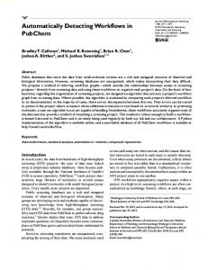
Figure 1: Overview of Product Ordering System using UML Packages
this paper. This system extends an existing COTS package, the Inventory System, by providing additional order capture and order processing services (see Figure 1). The new Product Ordering System sits on top of the existing COTS software. Both the existing Inventory System and the new services provided by the Order Framework make use of the same database (the Order Repository) which is yet another COTS package. To ensure a consistent looking user interface (GUI), the new system also replaces the current user interface of the Inventory System. As the paper unfolds, we will reveal more information about that system.
Mismatch Identification Approaches The following section will discuss both mismatch detection approaches in more detail. For more information about Component-Based Integration, please refer to [Gacek 1998] and [Abd-Allah 1996]. For more information about Model-Based Integration, please refer to [Egyed 1999b] and [Egyed 1999a].
Component-Based Integration Our component-based integration approach flags architectural mismatches based on descriptions of the various components to be used and the connections between them. For describing components we use a set of conceptual features rather than only architectural style information. This was a conscious decision based on the fact that the same style name may mean different things to different people, styles usually fix some aspects of their elements leaving others undefined [Shaw-Clements 1997], and moreover in large scale systems quite often a pure style does not suffice, forcing various adaptations for the specific task at hand. We also provide a finite set of connectors for the composition. Table 1: Product Ordering System, Subsystems, and their Conceptual Features Subsystem Pre-defined Style Background Information Backtracking Component priorities Concurrency Control unit Distribution Dynamism Initiating: Terminating: Encapsulation Layering Data: Control: Preemption Reconfiguration Reentrance Response time Supported Data Transfers Shared Variable: Explicit Data Connector: Shard Repositories: Triggering capability
Order Framework
Inventory System
Order UI
Inventory UI
Event-based in-house no no yes central single-node
Event-based in-house no no yes central single-node
yes yes yes
yes yes yes
no no yes
unknown unknown unknown
no no no off-line no unbounded
no no no off-line no unbounded
no yes no off-line no unbounded
unknown unknown unknown off-line Yes Bounded
no yes no yes
no yes no yes
yes no no no
No Unknown Yes yes
Main-Subroutine Database-centric in-house COTS no yes no unknown no yes none central single node single node
*** Items in Italics are refinements of the pre-defined styles. Their default value would be unknown otherwise.
The set of conceptual features we use for describing components is: backtracking, component priorities, concurrency, control unit, distribution, dynamism, encapsulation, layering, preemption, reconfiguration, reentrance, response time, supported data transfers, and triggering capabilities. A precise definition for these features and the possible values they may take will not be given here because of space limitations, but they may be found elsewhere [Gacek-Boehm 1998]. The connectors supported are: call, spawn, shared data, shared repository, data connector, trigger, and shared resources. While analyzing a given situation the set of component descriptions and their expected connections are used to traverse a set of rules and determine the kind of mismatches that are present1. When using our Architect’s Automated Assistant (AAA) tool, components may be described based on some pre-defined architectural styles and then refined, or simply based on their feature set. Additionally, some of their features may be left unconstrained, allowing for the analysis of partial descriptions. Since descriptions given to AAA are extremely high-level and at times incomplete, the output provided is a list of potential mismatches. This list is to be used by architects for further analysis as some potential risk sources. In our Product Ordering System example, the input used by AAA was the one provided in table 1 for the components, plus the connecting information depicted in Figure 1. The results obtained will be discussed shortly.
Model-Based Integration To address the view mismatch problem, we have investigated ways of describing and identifying the causes of architectural mismatches across UML views. To this end, we have devised and applied a view integration framework accompanied by a set of activities and techniques for identifying mismatches in a more automated fashion: mapping, transformation, differentiation (see Figure 2) [Egyed 1999b]. The system model represents the model base (e.g. UML model) of the designed software system. Software developers use views to add new information to the system model and to modify existing ones (view synthesis). Interacting with both the system model and the view synthesis is the view analysis activity. As soon as new information is added, it can be validated against the system model to ensure its conceptual integrity. This approach exploits redundancy between views (the very causes of view mismatches). For instance, view A contains information about view B, consequently this information can be seen as a
View Analysis System Model e.g. UML model
View Synthesis
Mapping (Cross-Referencing) - through names - through patterns - through association
Differentiation
Transformation
(Comparison) identify differences between model, rules, and constraints
(Extraction) - through abstraction - through patterns - through translation
(graphical and textual)
Figure 2: Model-Based View Integration Framework 1
Though we have a model using the Z formal language that can pinpoint exact mismatches based on precise descriptions [Gacek 1998], in this paper we will only be discussing the AAA tool, which requires less information and provides less accurate but much faster and cheaper feedback.
constraint on B. The view integration framework is used to validate these constraints and, thereby, the consistency across views. Since there is more to view integration than constraints and consistency rules, our view integration framework also provides an environment where we can apply those rules in a meaningful way. Therefore, we see view integration as a natural extension to mere view representation. The former extends the latter not only by rules and constraints but also by defining what information can be exchanged and how it can be exchanged. Only after the what and how have been established, can inconsistencies be identified and resolved automatically. •
•
•
Mapping: Identifies related pieces of information and thereby describes what information is overlapping. Mapping is often done manually through naming dictionaries or traceability matrices. We can automate mapping through the use of patterns, interfaces, similar usage, trace observations, and others. Transformation: Extracts and manipulates model elements of views in such a manner that they (or pieces of them) can be interpreted and used in other views (how can information be exchanged). Transformation can be categorized into basically two dimensions: abstraction (simplify or generalize detailed views) and translation (convert information for use in different types of views). Knowledge about patterns may support both. Differentiation: Traverses the model to identify (potential) mismatches within its elements. (Potential) mismatches can automatically be identified through either the use of rules and constraints or direct (graph) comparison. Mismatch identification rules can frequently be complemented by mismatch resolution rules. Automated differentiation is strongly dependent on transformation and mapping.
To date, we have applied our view integration framework on various UML views such as class and object diagrams, sequence diagrams, and state diagrams. Our framework was also used in connection with architectural models and styles (e.g. C2, Pipe-and-Filter, Layered, etc.) as well as design patterns.
Identifying Mismatches Having described the mismatch detection approach, the following will illustrate their usage on the Product Ordering System example we introduced previously.
Component Feature Clashes Currently, all the information available about our system is rather high-level. At this point in the development process we have no detailed architecture or design information available, however, as we had shown in Table 1, we have some clear understandings on what the conceptual features of the components look like. We also have the description of the interactions between the components, as seen in Figure 1 (e.g. Order Framework calls and shares repository with Inventory System). Using that information we can now perform a preliminary analysis on what potential mismatches (risks) may occur when building that system. Table 2 summarizes the results of that analysis. The table shows an excerpt of the mismatches identified by the Architect’s Automated Assistant (AAA) tool developed at USC [Gacek 1998]. Since the internal workings of our components are largely unknown, many of these mismatches are hypothesized. For instance, the mismatch that a node resource is overused is based on the observation that more than one component is using the same resource (a PC in this case). Thus, in this context the list presented in Table 2 should be seen more as a risk list. Nevertheless, special attention should be placed on that lists (as well as other risk lists) from this moment on. In case of more severe items, an initial exploration or even prototyping may be necessary to ensure that the project is still doable. For instance, the ninth mismatch sharing data with some components that may later backtrack is a serious risk. Here we need to explore whether the current database is able to deal with issues such as distinguishing different sources of input or supporting locking mechanisms.
Table 2: Excerpt of the List of Component Features Mismatches. 1. A layering constraint is violated. Bridging connector may ignore existing layering constraints. Violating subsystems: Order UI and Order Framework (on control layer); Inventory UI and Inventory System (control layering unknown) (on control layer); Order Framework and Inventory System (on control layer) 2. Different sets of recognized events are used by two subsystems that permit triggers. A trigger may not be recognized by some subsystem that should. Violating subsystems: Order UI, Inventory UI, Inventory System 3. A (triggered) spawn is made into or out of a subsystem which originally forbade them. May cause synchronization problems, as well as resources contention. Violating subsystems: Inventory UI and Inventory System (threads initiating unknown); Order Framework and Inventory System 4. A remote connector is extended into or out of a non-distributed subsystem. The subsystem(s) originally non-distributed cannot handle delays and/or errors occurred due to some distributed communication event. Violating subsystems: Inventory UI and Inventory System 5. A node resource is overused. Resource overusage such as memory and disk space. Violating subsystems: Inventory UI, Order Framework, Order UI, Inventory System 6. (Triggered) Call/Spawn to a private method. Method not accessible to the caller. Violating subsystems: Inventory UI and Inventory System (encapsulation unknown); Order Framework and Inventory System (encapsulation unknown) 7. More than one central control unit exists. All central control units assume they have absolute control on the execution sequencing. Violating subsystems: Order UI, Inventory UI, Inventory System 8. (Triggered) Call to a non-reentrant component. Component may already be running. Violating subsystems: Order UI and Inventory UI; Order UI and Order Framework 9. Sharing data with some component(s) that may later backtrack. Backtracking may cause undesired side effects on the overall composed system state. Violating subsystems: Order Framework and Inventory System 10.Sharing or transferring data with differing underlying representations. Communications concerning the specific data will not properly occur. Violating subsystems: Order Framework and Inventory System
Model Constraint and Rule Clashes Model-based integration takes a very different approach in identifying mismatches. Here, we try to actually analyze the solution model. For instance, when we take Figure 1, we can see that this figure imposes a number of constraints on our system. For instance, it states that only Inventory UI and Order Framework are allowed to talk to Inventory System, or that both the Order Framework and Inventory System may access the Order Repository (database) via the Network. These constraints can now be expressed more formally: Design[Order Capture UI depends-on Order Framework]; Design[Order Processing UI depends-on Order Framework]; Design[Inventory UI depends-on Inventory System]; Design[Order Framework depends-on Inventory System]; Design[Order Framework depends-on Network]; Design[Inventory System depends-on Network]; Design[Network depends-on Order Repository];
Based on this list, we can use these constraints to ensure consistency with lower-level design views (its realization) as well as with corresponding higher level views (e.g. architecture). Consider, for example, Table 3 which represents an architectural view of our proposed system. We see that, although the Product Ordering System consists of components of various styles, the overall system should follow a
Table 3: Layered Architecture Pattern to describe the Product Ordering System Product Ordering System User Interface (Order UI, Inventory UI) Order Framework (Customer, Payment, Order, OrderLine, Reorder) Inventory System Network (LAN) Order Repository layered style (the items in parenthesis are subcomponents). Like before, we can express constraints imposed by the architecture in a more formal way: Architecture[User Interface depends-on Order Framework]; Architecture[Order Framework depends-on Inventory System]; Architecture[Inventory System depends-on Network]; Architecture[Network depends-on Order Repository];
The translations of the above architecture and design views correspond to the Transformation activity we presented in the previous section. The above steps, which are rather trivial in this case, can easily be automated. What is not trivial, is how to establish mappings. In this example we need a mapping to describe how to relate architectural elements to design elements. Since they are not using the same names, mapping is more complex. It is however out of the scope to show automated mapping techniques here. If interested, please refer to [Egyed 1999a] and [Egyed 1999b] that show techniques for automatically performing both Mapping and Transformation on less trivial examples. Thus, for simplicity, let us assume that the mapping was done manually. This information can then again be transformed and represented in a more formal way: Design[Order Capture UI] maps-to Architecture[User Interface]; Design[Order Processing UI] maps-to Architecture[User Interface]; Design[Inventory UI] maps-to Architecture[User Interface]; Design[Order Framework] maps-to Architecture[Order Framework]; Design[Inventory System] maps-to Architecture[Inventory System]; Design[Network] maps-to Architecture[Network]; Design[Order Repository] maps-to Architecture[Order Repository];
Having established a mapping as well as having transformed both views into a common representation model, identifying mismatches between them is straightforward. The only item missing are mismatch rules for the Differentiation activity: For all [Architectural View Constraints] Exist [Design View Constraint]; Otherwise Raise Completeness Mismatch For all [Design View Constraints] Exist [Architectural View Constraint] Otherwise Raise Consistency Mismatch
The above notation is simplified for the benefit of readability. The mismatch analysis is twofold: 1) for each constraint imposed by the architecture, find at least one instance in the design which reflects this constraint (completeness issue) and 2) for each constraint in the design, verify that it does not violate any architectural constraint (inconsistency issue). For instance, in the first case, the architecture imposes a dependency from User Interface to Order Framework (see Table 3). The User Interface is represented by two subcomponents: Order UI and Inventory UI. Thus, we need to verify that there is at least one dependency from either Order UI or Inventory UI to the Order Framework. This dependency exists and, thus, there is no mismatch. An example of the second case is the dependency from Inventory UI to Inventory System (in Figure 1) in the design view. Here we need to verify whether this dependency
Payment
Order Framework Layer 1
Customer
Order
Customer
Account
OrderLine
Product
Order Framework Layer 2
Order
Product
Queue
Transaction
Payment
OrderLine
ProductQueue
Figure 3: Refinements of Order Framework Package (see Figure 1) violates any architectural constraints. Since we cannot find a dependency from User Interface (the correspondence of Inventory UI) to Inventory System we have identified a layering mismatch. The mismatch identified here corresponds to the layering constraint violation indicated by AAA. The first risk item in Table 2 indicated that the interaction of the components may not conform to some layering constraint. Through model-based integration we are actually able to analyze this risk in more detail and we find that it was indeed correct. This shows that risks identified through AAA are a nice starting point for identifying model mismatches later on. This also implies that many AAA mismatches can be either confirmed or eliminated through model-based integration. The above example shows a rather trivial case. However, the view integration framework presented in this paper can handle more complex scenarios and at this point incorporates a number of techniques for automated mismatch identification. Note that none of the integration techniques must yield correct results nor may it be assumed that all possibilities are captured by them. Human interaction will always be required. Nevertheless, many pieces can be automated and this automation can save substantial human effort. It is however out of the scope of this work to go into much more detail here. We will therefore only present one example on how to automate class diagram abstraction (transformation). Figure 3 shows two further refinements of the Order Framework. Although, we make use of the same names it is clear that Mapping alone is not sufficient in identifying mismatches between both views. For example, we see that Payment is part of Customer on the upper half of Figure 3, however, that relationship is more complex in the lower half. In order to verify that both figures describe relationships the same way, we can use the concept of Rose/Architect [Egyed-Kruchten 1999]. Rose/Architect identifies patterns of groups of three classes and replaces them with simpler patterns using transitive relationships. In class diagrams, a transitive relationship describes the relationship between classes that are not directly connected. A relationship may, however, exist through other classes (e.g. helper classes) which form a bridge between them (e.g. in case of our example Payment and Customer are not directly connected but a relationship is still given through the helper classes Transaction and Account). Figure 4 shows the Rose/Architect refinement steps for the case of the Payment to Customer relationship of our layer 2 design view (Figure 3). After applying two rules (rules 4 and 17 respectively)
Payment
Payment
Payment
Transaction
Use Rule 4
Use Rule 17
Account
Customer
Account
Customer
Customer
Figure 4: Abstraction of Payment to Customer Relationship using Rose/Architect we get a simplified pattern of two classes and a dependency relationship between them. If this is also done for the other classes we can automatically generate new constraints. For instance, from Layer 1 in Figure 3 we could automatically derive the constraint that Payment is part of Customer. After abstracting Layer 2, we would derive another constraint saying that Payment is dependent on Customer. This discrepancy is a strong indication of a mismatch. Using Rose/Architect on other parts of the layer 2 diagram would also indicate a mismatch between Order and OrderLine. This abstraction process is fully tool supported. As above examples have shown, both integration approaches have advantages and disadvantages, however, together they complement each other very well. Not all mismatches identified through component-based integration can be validated through model-based integration. This suggests that other view integration or risk handling techniques are necessary to bridge the gap. Whereas component-based integration depends strongly on existing architectural features information, the model-based integration approach is able to also handle domain specific constraints and rules on an ad-hoc basis. This is possible because the latter uses constraints and rules that can be both view specific (e.g. layer may not be skipped) and domain specific (e.g. Payment is part of Customer).
Related Work The lack of component and model integration is not a new discovery. Many model descriptions talk about the need of keeping the views consistent. Sometimes, process models provide additional guidelines on what tasks one can do to improve the conceptual integrity of architectures. For instance, a case study in using the WinWin Spiral Model [Boehm et al 1998] suggests using Architecture Review Boards [AT&T 1993] after the LCO (life-cycle objectives) and LCA (life-cycle architecture) stages to verify and validate the integrity of the analysis and design. [Sage-Lynch 1998] stress “the important role that architecture plays in system integration.” They present the need for three major views: enterprise view, systems engineering and management view, and technology implementation view – and they stress to ensure consistency among these views. [Nuseibeh 1995] wrote that “inconsistency is an inevitable part of a complex, incremental software development process” and that “the incremental development of software systems involves the detection and handling of inconsistencies.” [Perry-Wolf 1992] realized the importance of software architectures early on and they state as one of the four major benefits of architectures that they are “the basis for dependency and consistency analysis.” [Shaw-Garlan 1996] describe architecture very provocatively as being “a substantial folklore of system design, with little consistency or precision.” They further state that “software architecture found its roots in diagrams and informal prose. Unfortunately, diagrams and descriptions are highly ambiguous.” These references, and many more, talk about the need for (or lack of) integration. Nevertheless, they often do not describe the involved activities in detail. On the other hand, techniques that are sometimes suggested are often only aimed at making people talk to each other. (e.g. Architecture Review
Board [AT&T 1993] or Inspection [NASA 1993]). Although these techniques may yield very effective results, the actual activities of identifying and resolving defects are still done manually.
Conclusion This paper discussed two integration variations - component-based integration and model-based integration. We have shown the advantages and disadvantages of each approach and illustrated their usage on an example. The component-based integration effort is more high-level and may be used early on to identify potential mismatches (risk mitigation). Identified mismatches may be less trustworthy than the ones identified through model-based analysis, however, the component-based approach is able to deliver results with fairly little, even incomplete, specifications. Model-based integration on the other hand, works poorly in such an environment. Instead it needs fairly detailed and sufficiently complete specifications. However, it detects much more precise and trustworthy mismatches and can handle large amounts of redundant information. New information added to the model may be validated right away and, in case of mismatches, resolution options may often be provided as well. It is these orthogonal characteristics that make both approaches highly complementary. Both integration approaches can be used (and should be used) together. Currently, component-based integration has a strong tool support (AAA tool). Model-based integration, has some tool support, such as Rose/Architect for abstraction, SCED [Koskimies et al. 1998] for translation, OCL checker (Object Constraint Language) for constraint and rule verification. These tools are, however, only weakly interconnected at this point and more tool support is needed.
References Abd-Allah, A. (1996) "Composing Heterogeneous Software Architectures," Ph.D. Dissertation, Center for Software Engineering, University of Southern California, Los Angeles, CA 90089-0781, USA. AT&T (1993) “Best Current Practices: Software Architecture Validation,” AT&T, Murray Hill, NJ. Booch, G., Jacobson, I., and Rumbaugh, J. (1997) “The Unified Modeling Language for Object-Oriented Development,” Documentation set, version 1.0, Rational Software Corporation. Boehm, B. and Scherlis, W. L. (1992) "Megaprogramming," Proceedings of the DARPA Soft ware Technology Conference, April (available via USC Center for Software Engineering, Los Angeles, CA, 90089-0781). Boehm, B., Egyed, A., Kwan, J., and Madachy, R. (1998), “Using the WinWin Spiral Model: A Case Study,” IEEE Computer, July, pp. 33-44. Egyed, A. (1999a) “Automating Architectural View Integration in UML,” submitted to ESEC/FSE’99, http://sunset.usc.edu/TechRpts/Papers/usccse99-511/usccse99-511.pdf. Egyed, A. (1999b) “Integrating Architectural Views in UML,” Qualifying Report, Technical Report, Center for Software Engineering, University of Southern California, USC-CSE-99-514, http://sunset.usc.edu/TechRpts/Papers/usccse99514/usccse99-514.pdf. Egyed, A. (1999c) "Using Patterns to Integrate UML Views," submitted to OOPSLA'99, http://sunset.usc.edu/~aegyed/publications/Using_Patterns_to_Integrate_UML_Views.pdf. Egyed, A. and Kruchten, P. (1999) “Rose/Architect: a tool to visualize software architecture”, Proceedings of the 32nd Annual Hawaii Conference on Systems Sciences. Gacek, C. (1998) "Detecting Architectural Mismatches During System Composition," Ph.D. Dissertation, Center for Software Engineering, University of Southern California, Los Angeles, CA 90089-0781, USA. Gacek, C., Abd-Allah, A., Clark, B., and Boehm, B. (1995) “On the Definition of Software Architecture,” in Proceedings of the First International Workshop on Architectures for Software Systems - In Cooperation with the 17th International Conference on Software Engineering, D. Garlan (ed.), Seattle, Wa., 24-25, pp. 85-95. Gacek, C. and Boehm, B. (1998) "Composing Components: How Does One Detect Potential Architectural Mismatches?," Proceedings of the OMG-DARPA-MCC Workshop on Compositional Software Architectures, January.
Garlan, D., Allen, R., and Ockerbloom, J. (1995) “Architectural Mismatch or Why it’s hard to build systems out of existing parts,” IEEE Software, November, pp. 17-26. Koskimies, K., Systä, T., Tuomi, J., and Männistö, T. (1998) “Automated Support for Modelling OO Software,” IEEE Software, January, pp. 87-94. Nuseibeh, B. (1995) “Computer-Aided Inconsistency Management in Software Development,” Technical Report DoC 95/4, Department of Computing, Imperial College, London SW7 2BZ. Perry, D. E. and Wolf, A. L. (1992) “Foundations for the Study of Software Architectures,” ACM SIGSOFT Software Engineering Notes, October. Sage, Andrew P., Lynch, Charles L. (1998) “Systems Integration and Architecting: An Overview of Principles, Practices, and Perspectives,” Systems Engineering, The Journal of the International Council on Systems Engineering, Wiley Publishers, Volume 1, Number 3, pp.176-226. Shaw, M., and Clements, P. (1997) “A Field Guide to Boxology: Pre-liminary Classification of Architectural Styles for Software Systems,” to appear in Proceedings of COMPSAC 1997, Washington, DC. Shaw, M. and Garlan, D. (1996) “Software Architecture: Perspectives on an Emerging Discipline,” Prentice Hall.