Proceedings of the 2004 Conference on New Interfaces for Musical Expression (NIME04), Hamamatsu, Japan
Versatile sensor acquisition system utilizing Network Technology Emmanuel Fléty, Nicolas Leroy Jean-Christophe Ravarini
Frédéric Bevilacqua Real-Time Applications Team Ircam - Centre Pompidou – 1 pl. Igor Stravinsky 75004 Paris – France +33/1 44 78 48 43
Production / Creation Department Ircam - Centre Pompidou – 1 pl. Igor Stravinsky 75004 Paris – France +33/1 44 78 48 43
[email protected]
[email protected] ABSTRACT This paper reports our recent developments on sensor acquisition systems, taking advantage of computer network technology. We present a versatile hardware system which can be connected to wireless modules, Analog to Digital Converters, and enables Ethernet communication. We are planning to make freely available the design of this architecture. We describe also several approaches we tested for wireless communication. Such technology developments are currently used in our newly formed Performance Arts Technology Group.
Keywords Gesture, Sensors, Ethernet, 802.11, Computer Music.
movements of several dancers. We want to stress that we are planning to release the design of our architecture, and thus sharing our developments with the community2. A particular implementation of this design, the EtherSense will be commercially available shortly. As discussed below we found that most commercial acquisition systems, typically using MIDI protocol (Musical Instrument Digital Interface), were unsatisfactory for the increasingly complex sensing technology needed for performance arts. However Network Technology offers nowadays interesting opportunities. We describe in this paper first a flexible acquisition system architecture that connects to a various set of sensing channels with a high data-rate transmission. Second, we describe three different approaches for wireless modules that can be used with this architecture.
2. AVAILABLE TECHNOLOGY 1. INTRODUCTION A new research group has been formed at IRCAM since June 2003 for the development of technology for performance arts ("Pôle de Recherche sur les Technologies pour le Spectacle Vivant"). This research effort is established as an interdisciplinary endeavor between the arts, science and engineering. Close research collaborations are being established with artists including composers, choreographers, theater directors and new media artists. One of the research directions relates to motion tracking, recognition and analysis. As a matter of fact, Ircam has been intensively involved in gesture analysis and sensing for more than five years, as demonstrated by several artistic projects [1][2] and research works [4][5]. Our goal is to further develop both new technology for gesture sensing, applicable to performances, and develop/implement powerful movement analysis schemes. Particularly, we seek to incorporate research performed on human motion from different disciplines (dance, computer graphics, human-machine interface, artificial intelligence, physiology, cognitive sciences, medicine), with the ambitious aim to compute high-level parameters of movements from gesture data. As mentioned, this program includes the development of robust, cost-effective and versatile tools for motion sensing. We report here important steps towards this goal. Gesture sensing (controllers, augmented instruments, body gestures) requires accurate sampling as well as low latency, especially for the direct control of sound parameters with high-resolution control. After exploring the use of video tracking systems [3] for a year, we decided to renew with embedded sensors, enabling fast and accurate acquisition, as a complementary approach. Our design strategy is to develop a acquisition platform with high-quality digitization that can be used in several distinct configurations: from sensing the gesture of musicians to tracking the
Concerning data transmission, the MIDI standard has been used for about 20 years and remains a low cost and fast development solution for many sensors’ applications. However, despite of several improvements such as the running status [5], MIDI is a painfully slow medium with roughly only a thousand samples per second on a single MIDI link, as highlighted in Table 1. While resolution higher than the standard 7 bit data can be transmitted through multiple MIDI messages, the final bandwidth is seriously reduced when several sensors and/or high-resolution data are used. Table 1 : Comparing MIDI with USB Data rate (Hz) 1 sensor Data rate (Hz) 16 sensors
MIDI3 (7 bits) MIDI2 (14 bits) 1384 692
USB 1.1 (16 bits)4 ≈ 500,000
86.5
≈ 31,250
43.25
High-speed and high-resolution sampling can easily be achieved with today’s mid-range Analog to Digital Converters (ADCs), as found in computer sound cards. The next question regards the protocol and the physical layer for transmitting high data-rate under a relative standard form. As mentioned in previous publications [4][6], our aim was to investigate first current high-speed standard such as mLan (IEEE 1394, Firewire), USB and Ethernet. Nevertheless, the first two standards, IEEE 1394 and USB, were abandoned due to several “drawbacks”: • USB and Firewire are not compatible with long cable, which is a problem in live performance where computers are not always close to the stage. 2
www.forumnet.ircam.fr With running status 4 Calculated on a true 1 Mbytes/s transfer rate 3
NIME04 - 157
Proceedings of the 2004 Conference on New Interfaces for Musical Expression (NIME04), Hamamatsu, Japan
• Their implementation often requires writing custom drivers on the host computer. We have also been evaluating Ethernet and the CNMAT’s Open Sound Control (OSC) [7] for a year and a half for the following reasons: • Most computers have an embedded NIC • Ethernet is fast (10-100 Mbits/s – Gbits/s) • OSC is an open and fully described protocol at the application layer level, with available implementations in signal processing environments (Max/MSP, Pure Data, Eyesweb, jMax etc). A cross-platform C library also makes custom implementations easy. • Ethernet supports long cables (50m). • Ethernet layers are clearly documented by the RFCs, and are of course implemented on every Operating Systems. However, note that OSC is currently implemented on nonconnected network sockets (UDP, User Datagram Protocol) with potential data loss5. However, consequences are reduced on continuous data flow (99.99 % is “enough”6). Another drawback is that the transport time is not guarantied. However, if the packet period is much larger than the packet transmission time, the packet jittering is negligible. Moreover, OSC also features Time Tags, which makes possible to properly clock and schedule packets at the reception on the host computer. Finally, it is important to mention existing Ethernet digitizing devices. CNMAT used network technology for its audio and sensors digitizer, initially designed for Gibson™. La Kitchen7 manufactures two OSC systems. Nevertheless, they are built with commercial Ethernet brain boards, which are known for their relative low communication speed with the internal processor.
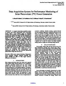
3. SYSTEM ARCHITECTURE Our goal was to build a versatile system suitable for gesture research, allowing us to experiment and to prototype with various sensors systems. The main requirement was to use a hardware base comparable to a fully manufactured and readyto-use product. Therefore, we decided to separate the Ethernet and OSC functions from a set of various application modules, including for example wireless receptors, digitizers, digital-toanalog converters and relays. We thus opted for a Mother Board (Ethernet & OSC) / Daughter Board (DB) architecture as described by figure 1. We chose to use Microchip™ Microcontroller Units (MCU), since they are well suited for quick prototyping. To overcome their relative low speed compared to processors or mixed architectures (ARM, PowerQuick, Rabbit, etc), we decided to use one MCU per card. We therefore obtained a real cluster, each MCU running its owns tasks and being handled under interrupt by the Mother Board (MB) through an integrated Parallel Slave Port (PSP). This approach is similar to a Personal Computer PCI bus and preserves versatility, reduces design repetition and is open to future developments [8].
A 10 Base-T chip is connected to the appropriate Ethernet compliant hardware, such as the insulation transformer, and to a MCU. This chip is programmed with a full UDP-ARP-ICMP stack that enables to format and to receive Open Sound Control compliant messages. Sensor
Sensor
Sensor
...
Accelerometer Pressure Sensor
RF Station
Output Command signals
Others Sensors
... Relays
Sensor
...
RF Station
Radio Link
... DACs
... Daughter Board 1 Digitizers ; - 16 channels - 16 bits
Daughter Board 2
Daughter Board 3
Command : - 8 relays - 8 DACs
RF reception
Bus
Mother Board
To Ethernet
Figure 1 : System architecture
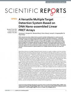
3.2 Peripheral daughter boards We wrote a simple Q&A protocol layer that allows for the communication between the mother and the daughter boards. These latter ones can be for example multiple channel digitizers, DACs, PWM servo controllers or a custom mix of several functions. A daughter board is specified by its address on the bus (PSP), its number of channels, its channel data size (1 bit, 8 bits, 16 bits, 32 bits), its direction (input, output, I/O) and its bus speed (up to 16 boards can be connected on the same bus). To avoid strong protocol dependency between DB and MB, the MB neither analyzes nor parses DB data. A DB transmits its contents on the mother’s request, with custom sampling period, which can be defined for each DB. Data is then “simply” inserted as a data list into the OSC buffer with an OSC command and “path” related to the concerned MB and DB. Data routing and unpacking can be therefore easily achieved on the host computer, as illustrated in figure 2.
3.1 Ethernet & OSC mother board We based the design our own Ethernet hardware on the wellknown application note from Crystal™.
5 6
OSC can also be implemented with TCP, but is slower.
Experiments showed no data loss over more than a million UDP packets sent. 7 http://www.la-kitchen.fr
Figure 2 : a simple OSC syntax example Configuration data can also be exchanged through OSC with /MBxx/CONF commands to configure the mother board or /MBxx/DByy/CONF to configure daughter boards. Interpretation or generation of received/sent data must be done by the host software which includes each card context (i.e. direction, track number, track size etc.).
NIME04 - 158
Proceedings of the 2004 Conference on New Interfaces for Musical Expression (NIME04), Hamamatsu, Japan
3.3 Implementation Example: the EtherSense
4.2 Prototype 1: time-slice sharing protocol
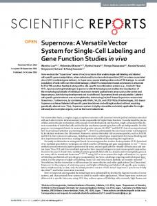
One end-user implementation of such an architecture is the EtherSense, a new sensors-to-OSC digitizing interface, which commercialization is currently planned. EtherSense is actually built with one Ethernet mother boards and two 16 channel 16 bit digitizing daughter boards. An additional LCD boards allows the user to configure among others UDP and IP parameters (IP address, port number). The device is housed into a half-rack unit, which makes transportation easy as well as racking. EtherSense is able to send 16 sensors on 16 bits at a 1000 Hz sampling rate. An optional 1400 Hz “overboost” setting is possible (no checksum computation), however note that the scheduler of real-time environments such as Max/MSP or Pure Data does not support such a rate.
A solution does exist for the use of regular license-free transceivers and multiple “simultaneous” transmitting devices: sharing the carrier. In our first prototype, we choose to implement a time-slice sharing protocol. We built a master station that communicates with the host computer through MIDI and several slave stations containing a 16 channel multiplexed ADC and 8 actuator control outputs. All stations use a common frequency carrier. However, communication is theoretically full-duplex since uplink and downlink are on two different carriers (French and UK ones). The master station successively interrogates the slaves to know if they have something to transmit or to tell them to update the actuators states. Such an approach is simple and works well. However the transfer rate efficiency is reduced by the message length required for interrogating the slave stations. Moreover, a 50:50 distribution of 0 and 1 must be used with digital wireless transceivers to maximize their performances and data-rate. When non-solicited, the wireless transceivers fall “asleep” and need to be “awaken” with a preamble before being able to receive data10. The usual solution is generally to use Manchester-coded data, which divide the data-rate by 2. One possibility is to recode the data on more bits roughly following the 50:50 distribution but significantly reducing the data-rate11. For prototyping we chose to send a wakening preamble before each transmission. Experiments showed that the minimum preamble length was 6 bytes at 31.25 Kbits/sec (MIDI). Thus, for questioning a slave station we need: 6 preamble bytes + 1 question byte = 7 bytes If answer is 16 sensors on 10 bits, we need: 6 preamble bytes + 16 * (2 bytes) = 38 bytes The efficiency is then:
4. WIRELESS PROTOTYPES As already mentioned, the architecture we described can easily host wireless receivers. Such capabilities are obviously necessary for movement tracking for performers such as dancers and actors [8]. Our approach is similar to UC Berkeley Embedded Systems Project [9] since we want to preserve modularity [10], however we want to focus on the quality of sampling rather than on miniaturization. Therefore, we decided to prospect the field of wireless technologies in order to build our custom portable sensor terminals. The following subsections describe three different approaches we tested.
4.1 Problems of wireless network for sensors and actuators Many people involved in today’s electronic hardware development started DIY projects when they were teenagers. One of those projects is the wireless spy microphone transmitter, essentially famous for two reasons: listening to sister’s secret conversations and illicit radio waves broadcasting. This last point illustrates what makes building a generic wireless digitizer difficult: Radio Frequencies (RF) are regulated. Moreover, the regulation rules are not the same over the world, which sometimes make the use of wireless microphones a nightmare when touring. Generally, only wireless audio equipment manufacturers can afford to buy RF licenses, prototyping is however possible by using “license-free” channels digital radio transceivers. Of course, the free radio space is very restricted and varies from a country to another. For instance, France allows free8 broadcasting on the 433 MHz band, shared by many walkietalkies devices. United Kingdom in on the 869 MHz band and the USA are on the 915 MHz band. Selectable channel FM transceivers also exist (Linx Technologies) but require one dedicated receiver per emitter. Building a single pair of wireless emitter and receiver is easy with license-free RF modules, which are now small and reliable using Frequency Modulation9. The real problem lays in building wireless equipment for several people on stage performing simultaneously. “Cheating” is possible by using transceivers from different countries. Thus, maybe up to three digitizers could be made, but the problem remains if more devices are needed. Although this solution might be nice for prototyping, it is sensitive to RF perturbation and is out-of-law.
8 9
With a transmitting power limited to 10 mW. http://www.radiometrix.co.uk
useful bytes 32 = = 71% total 45 It means that even with MIDI running status, we cannot expect a bandwidth higher than 490 Hz (0.71*692, see Table 1) on the wireless link (i.e. to be shared between several stations with several sensors each). Of course, variable data size could be sent, by refreshing changing only sensors. However, this solution is quite limited in terms of bandwidth and might be inconvenient for accurate and fast sensors sampling.
µ=
4.3 Prototype 2: Mixed architecture with Ethernet output In order to overcome the limitation previously reported, we built a second prototype based on SpacePort, a wireless transceiver with several interesting features, released by Radiometrix. It is composed of a 433 MHz switched emitter/receiver and an embedded MCU which manages the carrier sharing. Several sharing strategies are possible such as the previously described time slice protocol as well as a “listen before transmit” solution. This latter approach is based on statistics. Any slave station listens first to the carrier before trying to transmit. If the medium is free, it waits for a random delay before listening
10 The preamble is a group of several 0 and 1 transitions that initializes the data slicer of the receiver so that a received bit is sampled properly. 11 Transmitting at higher rate than MIDI was possible with the used transceivers but experiments showed a bigger sensitivity to noise and bit jittering.
NIME04 - 159
Proceedings of the 2004 Conference on New Interfaces for Musical Expression (NIME04), Hamamatsu, Japan
again. If the medium is still available, then it sends a message. This technique is called CSMA-CA, standing for Carrier Sense Multiple Access, with Collision Avoidance. We built a prototype based on an EtherSense daughter board, and battery powered pocket sized digitizing stations, sampling up to 16 sensors each (10 bit resolution). The system can be used by up to 10 dancers with a global bandwidth of 6000 symbols12 per sec. This way, we can expect 4 dancers with 4 sensors each at 410 Hz. Sensors data are received by the special daughter board and then passed to the Ethernet mother board which formats OSC messages. This architecture is interesting because it simply solves the question of multiple simultaneous users. Nevertheless, it is based upon a wireless link which uses an already very busy radio carrier.
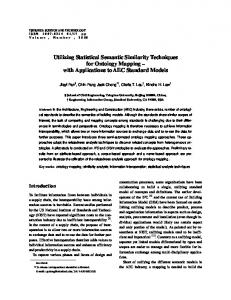
4.4 Prototype 3: The « WiFi » 802.11 solution Since we started our interface design with computer network technology, WiFi was the next logical step for experimenting high-speed wireless network solutions. WiFi (Wireless Fidelity) is actually the name of a certificate that ensures a product to be compliant with the wireless IEEE 802.11 standard (also known as Airport™). 802.11 adapters are now embedded in most laptops or can be added to a computer with cheap USB, PCI or PCMCIA hardware. WiFi is based upon the CSMA-CA protocol discussed before and features 13 frequency channels on the 2.4 GHz band (in which 5 are non-overlapping). The channels have been defined by an international organization, ensuring that WiFi hardware can be used all over the world13. Note that 802.11 is not Ethernet per se, it is a wireless hardware and protocol standard. However, it has been designed to transport Ethernet: sending OSC through WiFi is straightforward. Although several different WiFi hardware exist, most of them use a common 802.11 chipset like the Intersil™ one. Even among the different chipset manufacturers, the communication modalities with the firmware are in most cases identical. Writing driver is therefore generally easy, like the “Hermes” one for Linux. We oriented our choice toward a small Compact Flash WiFi card featuring the above named chipset. After working out the Compact Flash communication layer, derived from the PCMCIA standard [11] we wrote a custom driver for the WiFi chipset [12] and a UDP stack in a Microchip 18F microcontroller. A 16 bit multiplexed ADC from Burr-Brown™ and rechargeable batteries were added to the device to turn it into a pocket-sized WiFi sensor to OSC digitizer. The sensors’ data are exported with the same OSC syntax than with the Ethersense. Our first concern with this attractive development was reliability: What is the effect of ”going wireless” on the data flow? Simulations were performed with several of our WiFi prototypes connected in 802.11b14 ad-hoc mode to a host computer running Max. Open Sound Control messages were asynchronously sent by the stations to the host with a simple packet number increment, and tracking consecutive packet loss. WiFi fortunately contains a “retry” mechanism that allows a packet to be re-transmitted several times if the initial transmission process fails. This partially solves heavy bandwidth load as shown in the next table (packet loss over 65535 sent packets). 12
In our case a symbol is a 2 byte sensor’s digitized value. With exceptions on some channels, depending on local FCC regulations. 14 11 Mbits/sec 13
Table 2 : WiFi reliability test Sending period/Station number
1 station
1 ms 2 ms 3 ms 5 ms
x x x 0.024% 0.108% x no loss no loss > 1% no loss no loss no loss x : not applicable (too many losses)
2 stations
5 stations
It is clear that an average sampling period of 5 ms should be perfectly acceptable for up to 5 stations. More stations could be added by using different WiFi channels. Ad-hoc mode should be then replaced by the infrastructure mode with several onstage access-points configured on different channels.
5. CONCLUSIONS AND FUTURE WORK The general performance of the acquisition system architecture is excellent. We proposed different approach for the wireless modules, each having specific advantages and drawbacks as we discussed. Overall these developments are very promising. Current work is adding a LCD and rechargeable docking station for the WiFi prototype. We also plan to release electronic and code template for the Ethersense for the community to share our architecture, and designing custom DBs that can be connected to our OSC board.
6. REFERENCES [1]
Cera, A., Robbe, H. “Rew.” – Music and Dance performance for 2 dancers and electronics. Premiered in Lisbon, June 2003. [2] Bannerman, A., Caron D. “Connected Space” – Music and Dance performance for flute and electronics. Computer Music Class Concert, Ircam, October 2003. [3] Camurri, A., Coletta, P. “Eyesweb : A real-time platform for interactive dance and music systems” Proceedings of ICMC, ICMC 2000 – Berlin –Germany. [4] Fléty, E., “AtoMIC Pro : a Multiple Sensor Acquisition Device.” Proceedings of NIME, NIME 2002 – Dublin, MIT Europe – Ireland. [5] Wanderley, M., “Performer-Instrument interaction : applications to gestural control of sound synthesis”. Doctor’s Degree Thesis, Université Paris 6 – France [6] Fléty, E., Siguy, M. “EoBody : a follow-up to AtoMIC Pro’s technology" Proceedings of NIME, NIME 2003 – Montreal, McGill University – Canada. [7] Freed, A. and Wright, M. “Open SoundControl: A New Protocol for Communicating with Sound Synthesizers” In Proc. of the 1997 International Computer Music Conference. San Francisco, Calif. [8] Benbasat, A.Y., Morris, S.J, & Paradiso, J.A.A. “Wireless Modular Sensor Architecture and its Application in OnShoe Gait Analysis”. Proceedings of the 2003 IEEE International Conference on Sensors, October 21-24. [9] Berkeley Wireless Embedded Systems Project. Found at http://webs.cs.berkeley.edu/ [10] Holmquist, L. E. & Al “Building Intelligent Environments with Smart-Its”. In IEEE Computer Graphics and Applications, January/February 2004 (Vol. 24, No. 1), p p. 56-64. [11] Anderson, D., “PCMCIA system architecture” MindShare, Inc ed. – Second edition – 1998. [12] Intersil™, “PRISM Driver Programmers Manual”, NdA, Reference Manual – RM025 version 2. – March 2003.
NIME04 - 160