objects, then computing variation within and between classes. The results for .... [1] C.-C. Wang, C. Thorpe, and S. Thrun, âOnline simultaneous localization.
Autonomous Shape Model Learning for Object Localization and Recognition Joseph Modayil and Benjamin Kuipers Department of Computer Sciences University of Texas at Austin Abstract— Mobile robots do not adequately represent the objects in their environment; this weakness hinders a robot’s ability to utilize past experience. In this paper, we describe a simple and novel approach to create object shape models from range sensors. We propose an algorithm that defines angular constraints between multiple sensor scans of an object. These constraints are used to align the scans, creating a maximally coherent object shape model. We demonstrate the utility of this shape model, consisting of scans and poses, for both object recognition and localization. The results are accurate to within sensor precision.
I. I NTRODUCTION Several methods have been developed for mobile robots equipped with range sensors to learn the shape of the environment. However, objects inhabiting that environment are typically not adequately individuated, characterized, or represented, distinct from the static environment. If an object moves, methods exist [1], [2] for treating its sensor image as noise and preventing it from interfering with accurate mapping of the environment. If an object does not move, it is treated as part of the environment and included in the map. Our research goal is to show how a robot agent without prior knowledge of objects can learn from its own sensorimotor experience to separate meaningful individual objects from the surrounding environment, to form useful categories of objects, and to learn how to perform reliable actions involving these objects and categories. Once the agent can reliably predict the results of actions, it can form plans to achieve future goals. In prior work [3], we showed that individual moving objects could be separated from the static environment. The occupancy grid representation for local space can distinguish among cells that are reliably occupied, reliably empty, and dynamic. Sensor returns falling in dynamic cells can be clustered in space, then tracked over time, to yield prototype objects. A preliminary shape model and categorization of those object instances was created. Notice that this is a form of bootstrap learning, since it does not rely on prior knowledge of an object ontology, object categories, or individual objects in the world. In this paper, we show how coherent models of the shapes of objects can be created and used to reliably recognize objects and to localize the object in the robot’s egocentric reference frame. We propose an algorithm that defines angular constraints between multiple sensor scans of an object. These constraints are used to align the scans, creating a maximally coherent
object shape model. This shape model, consisting of scans and poses, is useful for both object recognition and localization. The problem of aligning scans occurs in different guises. Most commonly in robotics, scan-alignment is required for mapping and localization. These localization algorithms typically use some combination of scan-matching (matching points in scans to one another [4]), feature matching (Kalman filter approaches [5]), and grid based approaches (matching the points in a scan to an occupancy grid [6]). In contrast to these methods, the approach described in this paper relies on the angular constraints of a scan that bound the space occupied by the object. To clarify the distinction between using this approach and the point/feature/grid matching algorithms, consider the following thought experiment. Imagine using a range sensor to observe a leafy bush from several distinct poses in an otherwise featureless environment. Moreover, assume that no two scans observe data from the same part of the bush. This type of data from “porous” objects can cause significant problems for scan matching and feature based approaches. Probabilistic occupancy grid mapping approaches may create a fuzzy image given an appropriate likelihood function. However, the task should not be difficult to solve since the angle and the distance to the bush are tightly bounded. This is the underlying intuition behind the use of angular constraints. The paper is organized as follows. Section two briefly describes background motivations to object learning for robots. The following section describes the process of aligning sensor scans into a shape model. Section four describes the use of shape models for recognition and localization. Section five describes the experimental results. The final sections describe related work and our conclusions. II. BACKGROUND ON O BJECT L EARNING FOR M OBILE ROBOTS Finding objects in the environment is useful for interacting with the world. Using objects, it becomes simple to describe several of the interactions that a robot could learn in its environment, such as pushing a chair, hiding in a box, or putting garbage in the trash. Prior to learning these actions, the robot must learn to perceive and represent these objects. Research into object representations falls broadly into three categories. Appearance-based models represent the sensory impression of the object, storing sense impressions from particular viewpoints. Appearance-based models are particularly
important in vision [7], [8]. Structural models represent the geometry of the object. A geometric shape model permits the robot to reason about space, and to find consistent configurations of objects, namely those where the objects are non-intersecting. Structural models can also support object recognition and object localization (estimating the object’s pose in a robot centered reference frame). Finally, functional models capture the interactions of the object with a robot or human agent, thus yielding object affordances [9]. For this paper we only develop a structural model of the object’s shape. Developing the other aspects of an object representation is an ongoing but separate task. Although work on mapping has created a range of algorithms and data structures for representing the robot’s surroundings, these techniques do not adequately address the needs of object perception. Range sensors may only receive a few readings from an object at a distance, and this data sparsity can cause SLAM techniques to fail. An object may be moved by external forces while being observed by the robot, so tight motion models may not be available. Confronted with these problems, particle based localization methods can not adequately search the space of poses, and point based scan matching techniques lack sufficient data. Feature-based approaches are limited by the nearly non-existent texture in range sensor data. Faced with these weaknesses, a new scanalignment technique is desirable for learning object shape models. III. U SING ANGULAR CONSTRAINTS FOR SCAN - ALIGNMENT Given a set of sensor scans of an object, the task of scanalignment is to infer a pose for each scan to create a coherent shape model. (Figure 1(a)). We assume that the robot has a range sensor that returns the distance to obstacles along different angles. Moreover, we assume that the robot is capable of identifying the distance measurements that are reflected from an object instead of the environment, for example by background subtraction [10], [3]. We assume that the sensor takes readings at the angles in Θ, so the distance readings of a scan S are given by rS : Θ → RightBoundS , for all points o ∈ O. Thus, the lines LB S (pS ) and RB S (pS ) constrain the space occupied by the object. Hence, given two scans S, T of the object taken from different poses, as shown in Figure 1(a), the bounding lines LB T (pT ) and RB T (pT ) constrain xS (pS ), the scan endpoints of S. The above formulation is correct when there is no inaccuracy in the sensor readings. Real sensors suffer from multiple limitations including discretization, precision limits, and noise. Hence, we want to define and minimize the violations of these constraints. First, define the set of vectors representing constraint violations of the left bound of T , U ≡ {vec(x,LB T (pT )) |x ∈ xS (pS ), ψpT (x) > Lef tBoundT } ∪ {(0, 0)}
u∈U
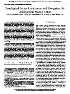
Fig. 3. Scans from an object (a) before and (b) after scan-alignment. Each triangle represents a pose and the two emanating rays indicate the left and right bounds. Scans are aligned by minimizing BV in Equation 3.
Given all the error vectors {eL , eR , eI }, scan-alignment becomes the task of finding poses such that all vectors are as close to zero as possible. This is accomplished by defining an objective function for boundary violations XX BV (M ) ≡ ||eL,S,T (pS , pT )||2 + S∈Λ T ∈Λ
(1)
The right exterior error vector (eR,S,T ) is defined correspondingly. Even if all exterior error vectors are zero, the scans may be significantly misaligned. Figure 2(b) demonstrates how no point in xT lies between the lines LOS (pS ) and LB S (pS ). Although this object shape is not impossible (as demonstrated in Figure 1(a)), it is improbable. Thus, we want to minimize the distance of the point set xT from the region between these two lines (LOS (pS ) and LB S (pS )). The exterior constraint vector handles points on the wrong side of LB S (pS ) so only LOS (pS ) remains to be considered. Therefore we define an interior error vector as the minimum length translation required by pT so that some point in xT (pT ) will fall on to the object support ray LOS (pS ) (see Figure 2(b)). Assume that ψpS (pT ) < RightBoundS . Then, using V ≡ {vec(q, ROS ) | q ∈ xT , ψpS (q) > RightObjectS } and W ≡ {q | q ∈ xT , ψpS (q) ≤ RightObjectS }, we define the interior error as � arg minv∈V ||v|| if W = ∅ eI,S,T ≡ (0, 0) otherwise.
(b)
||eR,S,T (pS , pT )||2 + ||eI,S,T (pS , pT )||2 ,
where vec(p, L) denotes the shortest length vector connecting the point p with the line L. Using this, define the left exterior error vector as the largest in U (see Figure 2(a)) eL,S,T (pS , pT ) ≡ arg max ||u||.
(a)
(2)
The above definition is used only when ψpS (pT ) < RightBoundS . Otherwise, the interior error vector is defined similarly using the left boundaries.
(3)
and then using a numerical optimizer to minimize BV by perturbing the poses. The resulting figures are visually accurate (Figure 3). IV. R ECOGNITION AND L OCALIZATION As mentioned in Section II, object recognition and localization are important for pragmatic reasons. Object recognition allows a robot to define a context for its current situation, and thus generalize from past experience. Object localization allows the robot to reason about the configuration of the environment, which is necessary for planning and acting with objects in continuous worlds. Fortunately, the tasks of object recognition and localization may be solved using the same error minimization technique used for scan-alignment. The tasks can be split up into three categories: (1) object recognition without model-alignment using features of an object instance, (2) object recognition by finding the best shape model-alignment of the instance to the canonical model, and (3) localizing the pose of the categorical shape model from a single scan of the object instance (object localization). Recognition by features without model-alignment can significantly reduce the computational load of object recognition. Aligning shape models can be computationally expensive, particularly if model-alignment must be performed for each object category. Computing coordinate-invariant features of an object instance and using the features to categorize the object will significantly simplify the recognition. First, given a shape model M we define the hull as the convex hull of the object endpoints. hull(M ) = ConvexHull(∪S∈Λ xS (pS )).
Since the hull is a polygon, computing the area, perimeter and center of mass are straightforward. For object recognition without shape model-alignment, we use the hull features of area and perimeter. These can be used for learning names for objects (supervised learning) or for learning to form object categories by clustering (unsupervised learning). The utility of a feature is inversely proportional to its variance. Ideally, the measurement varies less between object instances from the same category than between categories. For some tasks, merely recognizing the object is insufficient. The robot may need to find the transformation between the category model and instance model to apply knowledge from the object category, for example to identify the “front” of the object. Aligning the shape models also permits more discriminating recognition than is available through features alone. Model-alignment is performed by minimizing the BV error between the category shape-model, M and instance shapemodel N , namely fC (M, N ) ≡ min BV (M ∪ t(N, p)) p
red-chair
recycle-bin
garbage-can
dell-box
big-chair
5
4
3
2
(4)
where t(N, p) translates the pose of each scan in N by p. To speed convergence of the numerical optimizer, the initial value for p is selected so the center of mass of the hull of N coincides with that of M , so only the angle needs optimization. The final task we consider is object localization. When an object is moving but not under the robot’s direct control, the robot may know the approximate position of the object’s pose based on prior observations, but may need to know the object’s precise pose or position to act appropriately. We define this task as object localization. Localization is also solved by minimizing fC , where N contains the single scan. However, we assume an initial estimate of the pose is available. Also, since N is incomplete, the optimization occurs over all three dimensions of the pose p. Localization accuracy is limited for objects with rotational symmetries. V. E VALUATION The robot autonomously collected observations of selected objects that can be easily confused for one another. The robot was a Magellan Pro equipped with a SICK LMS 200. The sensor returned the distance to obstacles with a one centimeter precision, over a 180 degree viewing angle, with one reading per degree. A simplex algorithm from the scipy library for python was used for numerical optimization. The robot collected data by circling around an object selected by the experimenter. Five objects were selected from our lab, and each object was observed five times. The following subsections describe how this data was used to evaluate model construction, recognition and localization. A. Model construction The quality of the scan-alignment is good both visually and quantitatively. The scans for one object are shown in Figure 3, showing both the raw scan-alignment provided by the robot’s map-localization, and the aligned scans. The aligned
1
0
0
1
2
3
4
5
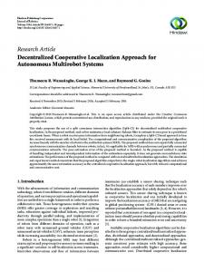
Fig. 4. Pictures of the objects with labels are given above. Each object is observed by the range sensor from approximately 40 cm above the ground plane. Scans of an object are autonomously gathered by the robot. For each object observation, the endpoints of the aligned scans are shown below the object’s image.
scan endpoints for all observed object instances are shown in Figure 4. A comparison of the BV error before and after scan-alignment is shown in graphs in Figure 5. Notably, the maximum external error is less than a centimeter, which is the sensor’s precision. An explanation is required for the effectiveness of a generic optimizer for scan-alignment. One caveat is that the starting poses arrive from robot map-localization in a known environment. This yields accurate orientations, but can suffer from visible errors in translation. For fixed orientations, the objective function is a piecewise smooth quadratic function, a good property for most optimization techniques. Allowing the angle to vary implies BV is no longer quadratic in theta, but the objective function is still differentiable and the starting values for theta are near the true value. B. Recognition Feature reliability for recognition without model-alignment was measured by computing the area and perimeter of all objects, then computing variation within and between classes. The results for feature reliability are shown in Figures 6 and 7. The first figure graphically demonstrates that most of the
fC error (min–max) recycle-bin big-chair garbage-can red-chair dell-box
recycle-bin 0.001–0.004 1.412–2.005 0.013–0.039 0.479–0.690 2.775–4.532
big-chair
garbage-can
red-chair
dell-box
0.001–0.005 1.662–2.643 0.193–0.376 0.239–0.439
0.001–0.005 0.609–0.986 3.073–5.632
0.001–0.003 0.958–1.789
0.002–0.006
Fig. 8. Residual error after shape model-alignment. Models are aligned by mining fC in Equation 4. The performance of model-alignment is measured by the range of fC error (minimum–maximum). The fC error can successfully discriminate between all tested objects.
Fig. 5. Modeling error measured by constraint violation. The graphs compare the error in the raw data with the errors after scan-alignment. The errors after scan-alignment are significantly smaller than the original data. The maximum length of an exterior error vector is less than a centimeter, indicating that the scans are aligned to within the sensor precision.
objects are separable on the basis of either perimeter or area, although the garbage-can and recycle-bin are confusable. The table demonstrates that the variance in perimeter is largely independent of object size, but the variance in area is significantly larger. Model-alignment for recognition was measured by comparing all observations of instance of one class with all instance from a second class (dropping self comparisons if both classes are the same). The minimum and maximum errors were measured and are shown in Figure 8. From the table, perfect classification can be achieved using the fC -error with a single threshold. Notably, fC -error does a better job than features for discriminating between garbage-cans and recycling bins. The use of fC -error for recognition is limited, because fC error cannot distinguish between objects that have the same hull. Still, since minimizing fC -error provides shape modelalignment, more detailed shape models can then be efficiently employed if required. C. Localization
Fig. 6. Perimeter and area are shape features that can discriminate between many object instances without shape model-alignment. Unsupervised learning by clustering is even possible to form categories. All categories are well separated except for recycle-bin and garbage-can. These categories can be separated after model-alignment (Figure 8) but that is more computationally expensive.
Feature Reliability recycle-bin big-chair garbage-can red-chair dell-box
Area 932 3288 889 2237 4257
σ 39 42 27 44 80
Perimeter 113.7 210.4 106.6 169.9 252.3
σ 2.3 1.3 1.5 1.6 1.7
Fig. 7. Feature reliability for object recognition. The area (in cm2 ) and perimeter (cm) along with their standard deviations. Note that the standard deviation in perimeter is small, making it a particularly useful feature for recognition.
Localization is evaluated in three steps. First, two instances of the same object are aligned using fC error. Second, a single scan from the second model is perturbed by a fixed amount. Finally, the perturbed scan is localized against the first model and subtracting the resulting pose difference from the unperturned scan provides a measure of localization error. The reported error measures the difference between object pose estimates in the robot’s reference frame. The results are tabulated in Figure 9. Relocalization error in position is typically less than 1 cm, and never greater than 3 cm. After localization, the maximum external error is less than 1 cm, indicating the final poses are consistent with the shape-model. VI. R ELATED W ORK We have demonstrated the use of angular constraints to solve the tasks of creating and using object shape models. Moreover, we have quantified the performance of our approach, demonstrating that it operates at approximately the precision of the sensor. Related work on shape modeling has focused on somewhat different issues. Biswas et al [10] demonstrate how occupancy grid models of an object’s shape can be constructed. Angelov et al [11] have demonstrated how articulated models can be constructed from dense 3D range data. Neither of these papers evaluate the empirical error of the resulting models, for recognition and localization. Shape model algorithms in the graphics community can create
Error
recycle-bin
big-chair
garbage-can
red-chair
dell-box
Localization position θ (m) (rad) 0.012 0.003 0.003 0.091 0.005 0.112 0.009 0.036 0.006 0.043 0.005 0.034 0.003 0.006 0.023 0.137 0.005 0.006 0.008 0.110 0.006 0.159 0.009 0.121 0.009 0.010 0.006 0.017 0.021 0.017 0.015 0.009 0.011 0.290 0.010 0.034 0.006 0.087 0.006 0.125
BV (m2 ) 0.000 0.000 0.000 0.000 0.001 0.001 0.001 0.001 0.000 0.000 0.000 0.000 0.000 0.000 0.000 0.001 0.001 0.001 0.001 0.001
fC max(eL , eR ) (m) 0.000 0.008 0.002 0.000 0.006 0.006 0.007 0.008 0.005 0.001 0.000 0.000 0.000 0.005 0.000 0.006 0.006 0.006 0.006 0.006
Fig. 9. Localization error for each object after a perturbation of (0.1 m, 0.1 m , 0.1 rad). One instance of the object is taken as the canonical model. From the each of the other four model-aligned instances of the object, a single scan is perturbed by (0.1 m, 0.1 m , 0.1 rad) and then the scan is localized to the model. The deviation between the pose after localization from the original pose is used to define a positional and angular error. Note that the errors in position (xy) and the exterior vectors are small (typically less than a centimeter).
dense three dimensional models of sculptures when given more computation and data [12], but do not address object recognition or localization. The idea of using geometric constraints in 3D mapping has been explored for buildings [13]. Similar ideas for inferring object structure from silhouettes or shadows have been pursued in vision, typically without the use of range information, but with notable exceptions. Esteban and Schmitt combine stereo with silhouettes to model objects in three dimensions [14], and a similar approach is taken in [15]. Both approaches provide a solution similar to the one in this paper for three dimensions but neither empirically quantifies the errors in model construction, recognition, and localization. VII. C ONCLUSIONS AND F UTURE W ORK The primary idea in this paper is that the underlying task in object shape model construction, recognition, and localization can be solved by minimizing violations of angular constraints. Scans are aligned by constraining the object data in one scan using bounds from other scans. We have quantified the effectiveness of this approach by measuring the residual errors. Moreover, we have shown that these errors are of approximately the same magnitude as the sensor precision. In future work, we will examine using the same approach
to 3D stereo vision data. Further work will use object localization to facilitate mining a robot’s experience for interesting behaviors and control[16]. ACKNOWLEDGEMENTS This work has taken place in the Intelligent Robotics Lab at the Artificial Intelligence Laboratory, The University of Texas at Austin. Research of the Intelligent Robotics lab is supported in part by grants from the National Science Foundation (IIS0413257 and IIS-0538927), from the National Institutes of Health (EY016089), and by an IBM Faculty Research Award. R EFERENCES [1] C.-C. Wang, C. Thorpe, and S. Thrun, “Online simultaneous localization and mapping with detection and tracking of moving objects: Theory and results from a ground vehicle in crowded urban areas,” in IEEE International Conference on Robotics and Automation, 2003, pp. 842– 849. [2] D. Hahnel, R. Triebel, W. Burgard, and S. Thrun, “Map building with mobile robots in populated environments,” in IEEE/RSJ Int. Conf on Intelligent Robots and Systems, 2002. [3] J. Modayil and B. Kuipers, “Bootstrap learning for object discovery,” in IEEE/RSJ Int. Conf on Intelligent Robots and Systems, 2004, pp. 742–747. [4] J.-S. Gutmann and C. Schlegel, “Amos: comparison of scan matching approaches for self-localization in indoor environments,” in Proceedings of the 1st Euromicro Workshop on Advanced Mobile Robots. IEEE Computer Society Press, 1996, pp. 61–67. [5] J. J. Leonard and H. F. Durrant-Whyte, Directed Sonar Sensing for Mobile Robot Navigation. Boston: Kluwer Academic Publishers, 1992. [6] S. Thrun, D. Fox, and W. Burgard, “A probabilistic approach to concurrent mapping and localization for mobile robots,” Machine Learning, vol. 31, no. 1–3, pp. 29–53, 1998. [7] S. Edelman, Representation and recognition in vision. Cambridge, MA: MIT Press, 1999. [8] F.-F. Li, R. Fergus, and P. Perona, “A Bayesian approach to unsupervised one-shot learning of object categories,” in Proc. Ninth IEEE ICCV, 2003, pp. 1134–1141. [9] A. Stoytchev, “Autonomous learning of tool affordances by a robot,” in Proceedings of the Twentieth National Conference on Artificial Intelligence (AAAI), 2005. [10] R. Biswas, B. Limketkai, S. Sanner, and S. Thrun, “Towards object mapping in non-stationary environments with mobile robots,” in IEEE/RSJ Int. Conf on Intelligent Robots and Systems, vol. 1, 2002, pp. 1014– 1019. [11] D. Angelov, D. Koller, H.-C. Pang, P. Srinivassan, and S. Thrun, “Recovering articulated object models from 3D range data,” in Proceedings of the Uncertainty in Artificial Intelligence Conference (UAI), 2004. [12] B. Curless and M. Levoy, “A volumetric method for building complex models from range images,” in SIGGRAPH, 1996. [13] R. Triebel and W. Burgard, “Improving simultaneous localization and mapping in 3d using global constraints,” in Proceedings of the Twentieth National Conference on Artificial Intelligence (AAAI), 2005. [14] C. H. Esteban and F. Schmitt, “Silhouette and stereo fusion for 3D object modeling,” Computer Vision and Image Understanding, pp. 367– 392, 2004. [15] G. K. Cheung, S. Baker, and T. Kanade, “Visual hull alignement and refinement across time: A 3D reconstruction algorithm combing shapefrom-silhouette with stereo,” in Proc. IEEE Computer Vision and Pattern Recognition, 2003. [16] M. Bennewitz, W. Burgard, G. Cielniak, and S. Thrun, “Learning motion patterns of people for compliant motion,” International Journal of Robotics Research, vol. 24, no. 1, 2005.