ICGST-GVIP, ISSN 1687-398X, Volume (8), Issue (III), October 2008
Autonomously Restructured Fault Tolerant Image Enhancement Filter *A.Guruva Reddy, **K.Sri Rama Krishna, ***M.N.Giri Prasad and @ K.Chandra Bhushana Rao *Research Scholar, Electronics and Communication Department, JNT University, Hyderabad, India ** Professor and Head, Dept. of ECE, V R Siddartha Engg College, Vijayawada. ***Professor and Head, Dept. of ECE, JNT University, Pulivendala @ Principal, V.S. Lakshmi Engineering College for Women, Kakinada, @ E-mail id:
[email protected] Abstract: Reconfigurable hardware based image enhancement technique when compared to the conventional method has an improved image quality even under adverse conditions such as contrast reversal and intensity gradients, angular uncertainties, blur caused by changes in depth field, scale changes, partial obliteration or missing features. In addition, parallel architectures can be used to ease the enormous computational load due to different operations conducted on image data sets. Reconfigurable computing is a new concept in the development of online adaptive machines. But, on the pessimistic side as the evolved circuit becomes large, the testability of the circuit becomes important and inherently testable logic need to coexist for autonomous restructuring in case of any internal fault. In this paper, in the first phase, schemes for testing the configured processing elements of a reconfigurable circuit evolved for image enhancement application is presented. In the second phase, the internal elements of the evolved circuit, if found faulty, is restructured such that the sparse Processing Elements (PE’s) replace the faulty PE’s both functionally and structurally. Simulation results show that the evolved circuit is inherently testable and can restructure itself by avoiding the faulty PE’s and make use of sparse ones.
Gate array (FPGA) in 2000, and James Hereford and Charles [3] describes a system that is robust with respect to sensor failure. The system utilizes multiple sensor inputs (three in this case) connected to a programmable device (FPAA) that averages the outputs from the sensors. The programmable device is programmed using evolvable hardware (EHW) techniques in 2004, and up to now the real-time implementation was limited by the usage of FPGA architecture in EHW. Using FPGA architecture in EHW, autonomously restructured fault tolerant image enhancement filter has been introduced in our work. Image enhancement refers to accentuation of image features such as edges, boundaries, or contrast. The enhancement process does not increase the inherent information content in the data, but it does increase the dynamic range of the chosen features to detect. Image enhancement includes gray level, contrast manipulation, noise reduction, edge crispening, sharpening, filtering, interpolation magnification, pseudo-coloring and so on. The difficulty in image enhancement is quantifying the criterion for enhancement and hence, a large number of image enhancement techniques are empirical and require interactive procedures to obtain satisfactory results. The outline of the remaining part of this paper is organized as follows: Section 2 discusses the reconfigurable computing and the types of the reconfiguring circuit. Section 3 explains the evolved image enhancement filter. Section 4 describes the implementation step of the fault tolerant image filter. Also illustrates the fault models and the power variation in evolved PE. Section 5 depicts the steps of the autonomous restructuring of the evolved circuit in the event of an internal fault. Section 6 shows the description of the different cores. Section 7 and 8 explain the implementation result. Section 9 summarizes the total presented work.
Keywords: Image Enhancement Filter, Reconfigurable computing, Embedded cores, Autonomous Restructuring, fault tolerant circuit.
1. Introduction Tetsuya Higuchi et. al.,[1] developed the concept of Evolvable Hardware (EHW), which can synthesize hardware circuits with higher level functions using Genetic Algorithms in 1996, L.Sekanina, et. al.,[2] discussed about the design of the special fast reconfigurable chip using common Field Programmable
1 35
ICGST-GVIP, ISSN 1687-398X, Volume (8), Issue (III), October 2008
The filtered image is compared with the original image and the fitness is evaluated. The VRC processes the nine pixel window and produces a single 8-bit value, used to replace the value of the pixel at (x,y), the particular point on which the window is centered at a given time. Thus, the principal function of the evolved filter is to force points with distinct gray levels to be more like their neighbors. The reconfigurable circuit is shown in figure 3. The parameters of the evolved network are: 9 inputs, 1 output, and circuit topology 6x4 and l-back=2.
2. Reconfigurable Computing Reconfigurable computing enables rapid adaptation to accommodate changing features in the image enhancement and allows rapid implementation of new standards and protocols on an as-needed basis. The advantage of reconfiguration circuit based image enhancement is that, it allows same hardware to perform multiple applications. Reconfigurable processing involves manipulation of the logic within the Field Programmable Gate Array (FPGA) [4] at run time and allows system designers to execute more hardware than they have gates to fit, which works especially well when there are parts of the hardware that are occasionally idle. There are two types of reconfiguration circuit, namely static and dynamic and are shown in figure 1 and 2 respectively. In the static structure, the device is configured only once and is application dependent. But, the hardware is still flexible in the design phase.
Design Configuration
Configure Logic
Execute
Figure 1 Evolving Static reconfiguration circuits
Dynamic structure allows hardware reconfiguration during runtime. A part of the reconfiguration hardware can be reconfigured while the rest stays the same and continue to execute. The duration between successive reconfigurations is programmable.
Figure 3 Block diagram of evolved image filter
4. Autonomous Restructuring Design Configuration
Configure Logic
The autonomous restructuring [10] model capability to take decisions as & when necessary and also reacting in an self –existence manner to build the architecture of Virtual Reconfigurable Circuit (VRC) in the evolved circuit is shown in figure 4 and the event of an internal fault consists of the following steps:
Execute
Figure 2 Evolving dynamic reconfiguration
•
3. Evolved Image Enhancement Filter The evolved filter specifies small spatial masks [5], [6] and attempt to capture the essence of the full filter function in the spatial domain. The spatial filter response is based on ordering the pixels contained in the image area encompassed by the filter, and then replacing the value of the center pixel with the value determined by the ranking result. The approach chosen here is based on functional level evolution [7] whose architecture can evolve any nonlinear function and uses an evolutionary algorithm to evolve the best configuration [8],[9].
• • • •
2 36
Identifying the faulty PE by monitoring the power level of the active PE’s. Introduce a core to identify the idle PE. Identify the functional and structural description of the faulty PE with the help of configuration bits. Identify the sparse PE nearest to the faulty PE and map it structurally and functionally. Update the configuration word to include the information about the new PE and delete the information about the faulty PE.
ICGST-GVIP, ISSN 1687-398X, Volume (8), Issue (III), October 2008
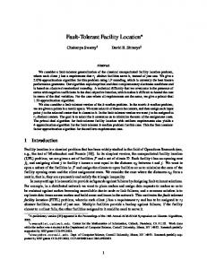
logic simulation tools. In stuck at model, a faulty gate input is modeled as stuck-at zero (S-A-0) and stuck-at one (S-A-1) fault. These faults most frequently occur due to gate oxide shorts or metal to metal shorts. In this work, the power consumed by each PE is monitored and is used as an indication of the healthy or unhealthy status of a PE. It is observed that the variation in power level is sufficient enough to detect the occurrence of (S-A-0) and (S-A-1) fault. "Stuck-at" refers to a condition where a defect causes a circuit node to become "stuck" at a logical one or logical zero. The proposed fault simulation and test generation are performed using gate –level tools designed to deal with stuck-at faults, ‘stuck at’ fault is typically caused by one or more shorted transistors within the cell, it can be caused by other things. If a cell was shorted to a zero level and we wrote (then read) all zeroes into the array, the device would pass. So to detect this fault we have to test every cell for the ability to store both a one and a zero. 5.2 Power Variation in Evolved PE A faultless PE performing the evolved function of “input1 + input2 +1” along with its power consumption is shown in figure 5 and 6. Similar graph corresponding to S-A-0 and S-A-1 fault in the same PE is shown in figures 7 and 8 respectively.
Figure 4 Schematic diagram for Autonomous restructuring
5. Fault Tolerant Image Filter The implementation of the fault tolerant image filter consists of the following steps: 1. Partition the algorithm into sections to be implemented on hardware and software separately. 2. Synthesize the computations destined for reconfigurable hardware into gate-level or circuit level description. 3. Map the circuit onto reconfigurable blocks and connect them using reconfigurable routing. 4. After compilation, the circuit is ready for configuration onto the hardware at runtime. 5. Continously monitor the status of the evolved circuit with the help of fault models. 6. İn the event of an internal PE fault, swap the faulty element with faultless sparse element and perform autonomous restructuring of the circuit. 5.1 Fault Models To deal with the existence of good and bad parts, it is necessary to propose a fault model, i.e., a model to detect the occurrence of a fault. The most popular model is the Stuck-At model. The short circuit/open circuit model can be a closer fit to reality, but is harder to incorporate into
Figure 5 Schematic of an evolved PE
3 37
ICGST-GVIP, ISSN 1687-398X, Volume (8), Issue (III), October 2008
6. Description of Different Cores Six major cores are used in this work for autonomous restructuring and are described in this section. 6.1 Core for Decoding active and idle PE (DC): This core outputs a 25 bit word with a bit ‘1’ implying that the PE is active. The decoded output of this core for an example code word of 1001010011011110111011101 is given in table 1. Table 1
Output Word -> 1001010011011110111011101 Active 1,4,6,9,10,12,13,14,15,17,18,19,21,22,23,25 Idle 2,3,5,7,8,11,16,20,24 6.2 Core for Fault identification (FIC): The input to this core is the power consumed by the active PE’s. If a particular PE is faulty (indicated by a observable variation in power consumption) a bit ‘1’ is loaded in the corresponding bit position of the 25 bit stream. The functionality of this core is illustrated in table 2.
Figure 6 Power consumed by the evolved PE under no fault condition
Table 2
Status No Fault PE10 Faulty
Output Word 0000000000000000000000000 0000000001000000000000000
6.3 Core for Selecting Sparse PE (SSC): This core gets the input from the DC and FIC cores and locates the sparse PE with the objective of keeping the routing distance minimum and replaces it both functionally and structurally. It gives a five bit value indicating the row (2 bits) and column (3 bits) position of the selected sparse PE. The functionality of this core is indicated in table 3. Table 3 Figure 7 Power consumed by the evolved PE under S-A-0 fault condition
6.4 Core for Functional mapping of PE (FMC): This core identifies the function performed by the faulty PE by decoding the relevant bits of the configuration word register. 6.5 Core for Structural mapping of PE (SMC): This core identifies the existing inputs to the faulty PE. 6.6 Autonomous PE restructuring core (ARC): The configuration word register is updated suitably based on the output of the above cores and its word value always reflects the current structure of the reconfigurable circuit. Figure 8 Power consumed by the evolved PE under S-A-1 fault condition
4 38
ICGST-GVIP, ISSN 1687-398X, Volume (8), Issue (III), October 2008
noise with mean 0 and variance 0.01, 0.02, 0.05, 0.08 and 0.1 are used for the initial evolution. Figure 11 is the original Lena bitmap of 128x128. Figure 12 is the Lena bitmap distorted by Gaussian noise with mean 0 and variance 0.03.Figure 13 is the result from Gaussian filter. Figure 14 is the resulting image of the EHW filter. On the other hand, this filter is implemented in VHDL version 2.0 and Microwind 2.6a on a PC with Intel (2.4 GHz) processor.
7. Implementation Results The results are shown in figure 9 and 10. A Stuck at one fault was introduced in the active element PE10. The injected fault introduced a power variation as shown in figure 9 and the faulty PE is reflected in the configuration word of the FIC core. Further the SSC core selects the sparse PE11 and the FMC and SMC performs the functional and structural mapping. The effectiveness of the autonomously reconfigured circuit is demonstrated by monitoring the power consumed by PE11 both when sparse and also after its induction into the circuit and this is shown in figure 10.
Figure 11 Figure 12 Figure 11. Represents Original Lena Image of size128x128, Figure 12. Image Distorted by Gaussian Noise of Mean 0 and Variance 0.003,
Figure 13 Figure 13. Image Filtered by Gaussian Filter, Figure 14. Image Filtered by EHW filter
Figure 9 Power variations of PE10
Figure 14
9. Conclusion A fault tolerant FPGA based image enhancement filter was presented in this work. The fault tolerant model consisted of multiple cores to assist fault detection and autonomous restructuring of internal processing elements of an evolved FPGA circuit.
References [1] Tetsuya Higuchi, et al., “Evolvable hardware with Genetic learning”, 1996 IEEE, pp. 29-33 [2]L. Sekanina, et. al., “Design of the special fast reconfigurable chip using common FPGA”, Proc. of Design and Diagnostics of Electronic circuits and systems- IEEE DDECS’2000, pp. 161-168 [3] James Hereford, Charles Pruitt, "Robust Sensor Systems using Evolvable Hardware," eh, p. 161, 2004 NASA/DoD Conference on Evolvable Hardware (EH'04), 2004 [4] Dhanaraj k.j et al., “FPGA Implementaion of a Pseudo Random Bit Sequence Generator Based on Elliptic Curves”, Proc. of ICGST-PDCS Journal, volume 7, issue 1, pp.23-31, May 2007. [5] G. Hollingworth, S. Smith, and A. Tyrrell, “Design of Highly Parallel Edge Detection Nodes using Evolutionary Techniques”, Proc. of the 7th Euromicro Workshop on Parallel and Distributed Processing, IEEE 1999.
Figure 10 Power variations of PE11
8. DISCUSSION The original and distorted bitmap images are stored in input buffer initially. At the same time using random number generator 16 initial chromosomes are generated. Simulations were performed using Gaussian noise [11] distorted bitmaps. The generality of EHW architecture has been tested by bitmap of IEEE test image, Lena as the target image at different distortion levels. All results are compared with the filtered results from the Gaussian filter. The bitmap images contaminated by Gaussian
5 39
ICGST-GVIP, ISSN 1687-398X, Volume (8), Issue (III), October 2008
[6] L. Sekanina, “Virtual Reconfigurable Circuits for Real-World Applications of Evolvable Hardware”, Evolvable Systems: From Biology to Hardware: Fifth International Conference, ICES 2003, pp. 186-198. [7] Vandenberg et al (1992), “Digital image processing techniques, fractal dimensionality and scale-space applied to surface roughness”, Wear, 159, 17-30 [8] L. Sekanina, “Image filter design with evolvable hardware. In applications of evolutionary computingProc. Of the 4th workshop on evolutionary computation in image analysis and signal processing EvolASP’02, Vol.2279, LNCS pp.255-266, 2002. [9] Torresen J., et al., “Implementing evolution of FIR filters efficiently in an FPGA”, EH, 2003, Proc. NASA/DoD conference, pp. 26-29. [10] Suresh et al (2002), “A Genetic algorithm approach for optimization of Surface roughness prediction model”, The International Jnl. Of Machine Tools & Manufacture, Vol. 42, pp. 675-680 [11] S. Md.Mansoor Roomi et al “A Recursive Gaussian weighted filter for impulse Noise Removal” Proc. of GVIP Journal, volume 6 issue 3, pp.33-37, Dec-2006.
2) Dr.K. Sri Rama Krishna is working as Professor & Head of E.C.E dept., V.R.Siddhartha Engg. College., Vijayawada. He completed his doctoral degree in the year 2001 from Andhra University, Visakhapatnam. His areas of interest include Neural networks, Wavelet Transforms, Genetic algorithms. Evolvable Computing, Image processing, signal processing.
Biographies
4) Dr. K. Chandra Bhushana Rao working as Principal, V.S. Lakshmi Engineering College for Women, Kakinada, he got his doctoral degree from Andhra University, Visakhapatnam. Under the Guidance of Prof. G.S.N Raju during 19992003.His areas of interest includes Antennas, Electro Magnetic fields, EMI-EMC and its allied areas.
3) Dr.M.N.Giri Prasad is working as a Professor & Head of ECE dept., Jawaharlal Nehru Technological University College of Engg., Pulivendula. He completed his doctoral degree in the year 2004 from Jawaharlal Nehru Technological University, Hyderabad. His areas of interest include Biomedical instrumentation, digital signal processing, VHDL coding and evolutionary computing.
1) A.GuruvaReddy is Research Scholar, Electronics and Communication Department, JNT University, Hyderabad, India. His areas of interest include Evolvable Computing, Image processing, signal processing, neural networks, Wavelet Transforms and Genetic algorithms.
6 40