rors in cache memories can corrupt data values, and can ... error detection/recovery schemes. First .... sum of the MTTF and the Mean-Time-To-Repair (MTTR).
Balancing Performance and Reliability in the Memory Hierarchy Ghazanfar-Hossein Asadi
Vilas Sridharan
Mehdi B. Tahoori
David Kaeli
Dept. of Electrical & Computer Engineering Northeastern University 360 Huntington Ave., Boston, MA 02115 E-mail: {gasadi,vilas,mtahoori,kaeli}@ece.neu.edu Abstract Cosmic-ray induced soft errors in cache memories are becoming a major threat to the reliability of microprocessor-based systems. In this paper, we present a new method to accurately estimate the reliability of cache memories. We have measured the MTTF (Mean-Time-ToFailure) of unprotected first-level (L1) caches for twenty programs taken from SPEC2000 benchmark suite. Our results show that a 16 KB first-level cache possesses a MTTF of at least 400 years (for a raw error rate of 0.002 FIT/bit.) However, this MTTF is significantly reduced for higher error rates and larger cache sizes. Our results show that for selected programs, a 64 KB first-level cache is more than 10 times as vulnerable to soft errors versus a 16 KB cache memory. Our work also illustrates that the reliability of cache memories is highly application-dependent. Finally, we present three different techniques to reduce the susceptibility of first-level caches to soft errors by two orders of magnitude. Our analysis shows how to achieve a balance between performance and reliability. keywords: soft errors, error modeling, caches, refresh
1
Introduction
Cache memory is a fundamental component used to enhance the performance of modern microprocessors, and its reliability is essential to assure dependable computing. Errors in cache memories can corrupt data values, and can easily propagate through the system to cause data integrity issues [28]. The main threat to the reliability of cache memories is soft errors. Soft errors, also called transient errors, are intermittent malfunctions of the hardware that are not reproducible [19]. These errors, which can occur more often than hard (permanent) errors [10], arise from Single Event Upsets (SEU) caused by strikes from energetic particles such as neutrons and alpha particles. Researchers have shown that in current systems, memory elements are the most vulnerable system component to soft errors [6, 16]. Soft error
rates for cache memory are projected to increase linearly with cache size for the next several years [7, 11]. Many commonly used protection techniques such as byte- or line-based parity or SEC-DED ECC (Single Error Correct-Double Error Detect Error Correcting Codes) use spatial redundancy to protect memory elements [13]. Unfortunately, several problems can arise when using these error detection/recovery schemes. First, redundancy incurs area overhead, which increases proportionately with the cache size. For instance, a 32 KB cache that supports byte parity requires an extra 4 KB just for the parity. Second, redundancy consumes significant additional power for the redundancy storage and logic. Third, to maintain high throughput, the redundancy checking hardware should not increase the L1 cache access time significantly. Using redundancy schemes for L1 caches (especially SEC-DED codes) can add an extra clock cycle to the L1 hit time, which can severely degrade performance. The last issue related to these redundancy techniques is that they offer unbalanced protection for IL1 and DL1 caches. This happens when the MTTF of the IL1-cache is much less than the MTTF of the DL1-cache or vice versa. As shown in our experiments, one of these situations occurs for almost 80% of the programs studied. For instance, consider an application where the MTTFs of unprotected IL1cache and DL1-cache are 10 years and 1 year, respectively. Using byte parity or ECC, the reliability of each cache increases, but unequally. Note that the reliability of the overall system depends on the least reliable component. Scrubbing is another technique that can be used to improve cache reliability in conjunction with SEC-DED ECC [23]. Scrubbing involves reading values from cache/memory, correcting any single-bit errors, and writing the bits back to cache/memory. While scrubbing can be applied to L2 caches, it is not typically used for L1 caches, since it can interfere with processor access to the L1 and reduce the effective L1 bandwidth. Moreover, scrubbing would call for dedicated hardware, which significantly increases the design complexity and cost of the system [13].
Due to the difficulties mentioned above, L1 cache reliability remains a major concern. Since it is difficult to provide guaranteed reliability for caches, caches are often disabled in safety-critical applications [4]. By disabling the cache, the area susceptible to SEUs is drastically reduced and so the processor’s dependability is dramatically increased. The major downside is that running in disabledcache mode seriously impacts performance. This large performance loss may not be tolerable for many applications. In order to make informed decisions about the level of protection needed for cache memories, we need a method to accurately estimate cache reliability across different cache organizations and target workloads. Once we understand how susceptible a cache is to SEUs, we can make decisions about what prevention or protection schemes to implement. Most previously proposed reliability estimation methods for cache memories have been based on fault injection (FI) strategies [4, 8, 14, 22]. When using a FI strategy, a limited number of memory addresses are targeted. Several workloads are then run to measure the number of detected failures. These steps make FI studies both time-consuming, due to the large number of runs, and prone to inaccuracy, due to the limited number of addresses targeted. Fault injection can be performed by software or radiation equipment. While software-based FI techniques can be employed in the design phase, radiation-based FI techniques can not be used before the actual device is fabricated. Moreover, radiation-based FI techniques are very costly and not commonly available. They are mainly used for characterizing the device or the technology rather than a particular design. In this paper, we present a new method that can accurately estimate the reliability of an unprotected or partially protected cache memory. We report on the residency time of critical words (CW) in the cache. A CW is a word in a cache that is guaranteed to propagate to other locations in the memory system or to the CPU. We have developed a simulation model that considers a two-level cache hierarchy and measures the reliability of L1 caches when running the SPEC2000 benchmark suite. Our results show that the MTTFs of a 16 KB L1 instruction cache and a 16 KB L1 data cache are at least 700 and 400 years, respectively, if the raw error rate equals 0.002 Failure-In-Time (FIT) per bit. However, these MTTFs are significantly reduced with higher error rates and larger cache sizes. Our results also show that the reliability of cache memory is highly application-dependent. Our study also finds that, on average, a DL1-cache is twice as susceptible to SEUs than an IL1-cache. Our reliability estimation method can be extended to estimate the reliability of cache memories protected by byte-parity or SEC-DED schemes. We also analyze the effects of various cache organiza-
tions on reliability. Our experiments demonstrate that for some programs, larger L1 caches can reduce reliability by up to 10 times, while system performance is improved only by 10%. We describe three different approaches to increasing reliability, while also considering the impact on performance. We study the utility of an operating system technique called flushing to increase the reliability of cache memories. Our results show how the error rate can be reduced up to 15 times, while only sacrificing 10% of the original performance. We also investigate how a write-through cache can positively impact reliability. Finally, we propose a refetching technique to refresh the L1 data cache blocks, which can have a dramatic impact on improving reliability. The rest of this paper is organized as follows. In Section 2, error rate and reliability background is described. In Section 3, our reliability model is described. In Section 4, experimental results are presented. Finally, Section 5 concludes the paper.
2
Background
When a particle strikes a sensitive region of an SRAM cell, the charge that accumulates can flip the value stored in the cell, resulting in a soft error. Soft errors are often classified as Detected/Unrecoverable Errors (DUE) or undetected errors (which are included in a more general class of errors called Silent Data Corruptions (SDCs)) [18]. The Soft Error Rate (SER) for a device is defined as the error rate due to SEUs. A system’s error budget is usually expressed in terms of the Mean Time Between Failures (MTBF), which is the sum of the MTTF and the Mean-Time-To-Repair (MTTR). Failures-in-Time is another commonly used error rate metric. FIT error rates are inversely proportional to MTBFs, if the reliability function obeys the exponential failure law [9]. One FIT is equal to one failure in a billion hours (1-year MTBF equals to 114,000 FIT). Current predictions show that typical FIT rates for latches and SRAM cells (measured at sea level) vary between 0.001-0.01 FIT/bit [7, 11, 20]. The overall FIT rate of a chip is calculated by adding the effective FIT rates of all components of the system. The FIT rate of each component is the product of its raw FIT rate and its associated Vulnerability Factor. The Vulnerability Factor (VF) is defined as the fraction of faults that become errors [17]. So, the FIT rate of the entire system can be computed as follows: � raw F ITElement(i) × V F (1) F ITChip = i
The reliability of a chip during the period [0, t] is defined as the probability that the chip operates correctly throughout this period [9]. The reliability of a chip at time t can be computed as follows: −t
ReliabilityChip (t) = e−F ITChip ×t = e M T T FChip
(2)
3
Reliability Model
The reliability of cache memories can impact the overall system. Data corruption in instruction and data caches can be propagated to the processor’s registers, and corrupted data can be written back to main memory, committing an erroneous result. A cache memory stores instructions or data in a data RAM, and includes address tags that are stored in a tag array. In most L1 data caches, every line has two status bits: a valid bit and a dirty bit. For a 16 KB IL1 cache and a 16 KB DL1 cache possessing the cache parameters shown in Table 1, the tag addresses will occupy 1.25KB and 1.38KB for IL1 and DL1, respectively. To properly compute overall cache reliability, we consider errors in address tags and status bits, as well as errors in the data RAM. Our results show that (on average) more than 90% of cache failures will be due to errors occurring in the data RAM, and less than 10% of cache failures are due to errors occurring in address tags and status bits.
3.1
Errors in data RAM
We define Critical Words (CW) as those words in the cache that are either eventually consumed by the CPU or committed to memory by a write. In other words, if the CPU reads a word from the cache or a dirty word of the cache is written to the memory, it is a CW. The Critical Time (CT) associated with a CW is defined as the time period in which the context of that CW is important. CT is the interval between the cycle the word is brought into the cache and the cycle it is used by the CPU; or the interval from the cycle in which the last modification is done on the word by the CPU, to the cycle in which the word is written back to memory. If an error in a CW is encountered during its critical time, this can result in an erroneous value being propagated. All other words that are not critical are called Non-critical Words (NWs). Any failure to NWs should not affect the correct operation of the system. Suppose that the words W 1 and W 2 are fetched into the cache in cycle 10. W 1 is read by the CPU in cycle 40 and W 2 is updated by the CPU in cycle 30. In cycle 50, W 1 is replaced by another word and W 2 is written back to the memory. The CT of W 1 is calculated as 40 − 10 = 30 and the CT of W 2 is calculated as 50 − 30 = 20. Note that the replacement time in the read operation (cycle 50) and the entrance time in the write operation (cycle 10) do not affect the critical time. This is shown in Figure 1.
3.2
Errors in address tags and status bits
To investigate the impact of errors in address tags and status bits, we extend the classification provided in [13] and then study how these errors individually affect the reliability of caches. There is a tag address associated with every cache line of data or instructions. The width of the tag is a function
Read by CPU Replacement
Enter to cache
CT1 W1 Enter to cache
Write by CPU
W2 0
10
20
30
CT2 40
Write back to Memory
50
time
Figure 1. Critical words and critical time definitions. of the size of the address, the number of cache lines and the associativity of the cache. Bit changes in the tag array may cause pseudo-hits, pseudo-misses, replacement errors or multi-hits, as described below: Pseudo-miss: the tag associated with the indexed entry does not erroneously match the requested address tag. Pseudo-hit: the tag associated with the indexed entry erroneously matches the requested address tag. Replacement error: the tag address of a line is changed after the the line has been written to. Multi-hit: the tag that was modified matches a tag entry in the same cache set. A pseudo-miss does not introduce a failure into the cache system because it only generates an unnecessary access to the next level of cache hierarchy or to the main memory. The soft error will be effectively overwritten. In the case of a pseudo-hit, the processor is sent the wrong data on a read or updates the wrong address on a write. The tag address contains the most-significant bits of an address. So an error in a tag address will change the original address to a location potentially far away in the address space. Considering the property of spatial locality, it is highly probable that this line would be replaced before it would be used by the CPU. To maintain high accuracy in our results, we faithfully model pseudo-hits in our simulations. A line that experiences a multi-hit, like one that experiences a pseudo-hit, is unlikely to be re-referenced. A replacement error represents the majority of all failures that are due to tag address errors. Consider a line l that is fetched into the data cache, is written to by the CPU in cycle t1 and then is written back to the memory in cycle t2. This period is also the critical time for the tag address portion of this line, because any failure in the tag address during this period will cause errors in two main memory locations. First, the line possessing the original address was expecting the new updated value, but this store is never performed. Second, the line associated with faulty address in the main memory is incorrectly updated with the stored value. Dirty bits are used only in data caches. An error occurring in a dirty bit, when changing from 0 to 1, does not
Config. Parameter
Value Processor
Functional Units
4 integer ALUs 1 integer multiplier/divider 4 FP ALUs 1 FP multiplier/divider LSQ / RUU Size 8 / 16 Instructions Fetch / Decode Width 4 / 4 instructions/cycle Issue / Commit Width 4 / 4 instructions/cycle Fetch Queue Size 4 instructions Cycle Time 1 ns Cache and Memory Hierarchy L1 Instruction Cache 16KB, 1-way, 32 byte lines (IL1) 1 cycle latency L1 Data Cache 16KB, 4-way, 32 byte lines (DL1) Writeback, write alloc. 1 cycle latency L2 256KB unified, 4-way 64 byte lines, 6 cycle latency Memory 100 cycle latency Branch Logic Predictor Combined bimodal 2KB table two-level 1KB table 8 bit history BTB 512 entry, 4-way Mis-prediction Penalty 3 cycles Table 1. Default Configuration Parameters affect data integrity. But when a soft error causes a change from 1 to 0 in a dirty bit, if this line is replaced before it is written to again, the new value of the line is lost. In the case of an error in a valid bit, if the bit changes from 1 to 0, it depends whether the line was dirty or not. If the line was not dirty, only a miss may occur, but no data integrity will occur. However, if the line was dirty, the most recent data written to the line will be lost. Alternatively, if an error changes the valid bit from 0 to 1, this will change the status of an invalid line to a valid line. We ignore this case in our computation because the number of invalid lines is very small as compared to the number of valid lines (less than 0.2% in our experiments). Additionally, this line should never be requested by the CPU and will eventually be replaced by another clean line. Note that it is possible that a dirty line is read by the CPU once or several times. In this case, one should take care so that the critical time of read operations and the critical time of dirty lines do not overlap. We have been careful to check for these instances in our experiments. To summarize this section, the number of important bits in a clean (not dirty) line during a read operation equals the word size in bits. But the number of important bits in a dirty line equals linesize+tagsize+2. The line size and the tag
size are in terms of bits, and we add 2 bits to account for the dirty bit and the valid bit. Note that our estimation method for data RAM and tag-addresses is very accurate. That is, we include in our modeling both the data RAM or the tagaddresses. These two contain more than 99% of all of the bits in a typical cache. In this paper we approximate the vulnerability of the status bits. The accuracy of our method with respect to these approximations is more than 99.5%. There is the fact that an erroneous value from the cache, either read by the CPU or written back to the memory, may be later over-written by the correct value (e.g., a silent store may occur [15]). First, note that our work is focused on computing the reliability of cache memory, not the entire system. Second, the vulnerability of the cache memory is always less than or equal to the system-level vulnerability. In other words, even if error-masking possibilities occur in the system, the computed reliability (expressed in terms of MTTF) using our estimation method is always more than or equal to the actual reliability of the system (i.e., the estimated reliability is always guaranteed.) Note that the guaranteed reliability for components of a system is important because the reliability of the entire system is determined by the least reliable component.
3.3
Reliability computation
The reliability of the cache system only depends on the correctness of the CW words. If a CT is assigned to every CW, then the vulnerability factor of the cache system can be computed as follows [17]: � residency time of all critical words V FCache = T otal Execution T ime × M (3) where, (M = cache size in number of words) and V FCache =
�N
i=1 CTi TT × M
(4)
where, T T = total execution time, and N = number of CW s. Note that V FCache is the probability of error in a cache word, and its value is between 0 and 1. If every word is critical for the entire time duration, the VF=1. We assume that the failure rates of all words are statistically independent, and hence, linearly uncorrelated. We also assume that all cache elements have the same failure probability. Using the above assumptions and comparing expressions (1) and (3), the entire FIT rate of the cache system can be obtained as follows: �N � CTi (5) raw F ITW ord(j) × i=1 F ITCache = TT × M j F ITCache
raw F IT per bit × Bpw × = TT
�N i=1
CTi
(6)
(T T = T otal Execution T ime, N = N umber of CW s, Bpw = Bits per word) To compare the reliability of cache memories independent of raw FIT rates, we define the vulnerability of a cache system during the execution of a program as follows: F ITCache (7) raw F IT per bit Comparing expressions (6) and (7), the following expression can be derived: �N Bpw × i=1 CTi (8) V ulnerabilityCache = TT Expressions (6) and (8) will be used in all experiments to evaluate the FIT and the vulnerability of caches. As CTs increase, the vulnerability of the cache system increases as well. In other words, the longer the duration that critical data or instructions stay in the cache, the greater the probability that an error in the cache will be propagated to the outside. Cache organization can affect the vulnerability of caches to SEUs. Some organization parameters that impact vulnerability include: prefetching policies, associativity, and the total cache size. In this paper, we show the impact of cache size on both performance and reliability of the cache system. Note that to estimate the vulnerability of the cache system, it is necessary to compute the CT value of every cache word. V ulnerabilityCache =
4
Experimental Results
For our experimental setup, we use SimpleScalar 4.0 [2] and sim-outorder to get detailed information including cache miss rates and Instructions Per Cycle (IPC). In our experiments, IPC is used as the performance metric. The default configuration parameters are detailed in Table 1. Two parameters, IL1 cache size and DL1 cache size, are varied across experiments. We selected twenty programs from the SPEC2000 [25] benchmark suite. All benchmark programs were compiled targeting the Alpha ISA [12]. The IL1 and DL1 miss rates are reported for the default configuration. In all experiments, we fast forward past the first 500 million instructions and present detailed results for the next 500 million instructions. In a subset of the benchmark programs (specifically, ammp, equake, fma3d, mcf and vpr), we see significantly different IPCs when using our simulation points versus running the programs to completion. To validate our results, we re-ran these five programs using the SimPoint simulation points, as specified in [21]. The resulting vulnerability values are consistent with the vulnerability results reported in Figure 2 through Figure 15, even though the absolute IPC numbers differ. These experiments have been executed on c with dual 2.4 Ghz Xeon procesa Dell PowerEdge 2650 � sors and 4 GB of memory, running the Redhat Linux 9.0 c operating system. �
4.1
Reliability of L1 caches
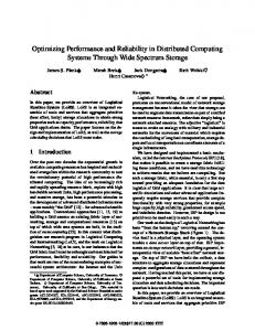
To evaluate the reliability of IL1 and DL1 caches, we have extended the SimpleScalar source code to integrate our reliability estimation method. Using SimpleScalar, we can measure the reliability of a typical program in less than 40 minutes on our Dell PowerEdge system. Our reliability estimation method can be used during early design phases. The main limitation of FI methods is the time to complete a study. The entire program is run for each injected fault and then compared to a clean run. For example, if we wanted to test 16 K fault locations in the IL1 cache, the three steps (1- fault injection, 2-program execution, and 3- results comparison) would need to be repeated 16 K times. But using our estimation methodology, we run the whole program only once. Thus, we obtain a speedup over software-based FI techniques that is proportional to the number of simulated faults. Figures 2 and 3 show the MTTFs for the IL1 and DL1 for twenty SPEC2000 benchmark programs. The MTTFs of these programs have been computed for three different raw FIT rates (0.002, 0.005, 0.01). As shown in these figures, the MTTF of the IL1 and DL1 caches (as configured) for all 20 programs is at least 400 years when the raw FIT rate is 0.002. In this case, providing protection to support short-time missions may be unnecessary. For example, assume that bzip is the target application. The reliability of the IL1 and DL1 caches for a six-month execution period can be calculated according to expression (2) as follows: −0.5
ReliabilityIL1 (6 months) = e 2915 = 0.99983 −0.5
ReliabilityDL1 (6 months) = e 1382 = 0.99963
(9) (10)
Now consider if we run mesa in a noisy environment (i.e., FIT=0.01). If we consider the reliability of this program over a longer execution period (10 years), we can compute the reliability of the L1 cache as follows: −10
ReliabilityIL1 (10 years) = e 160 = 0.939 −10
ReliabilityDL1 (10 years) = e 118 = 0.918
(11) (12)
This level of reliability is not acceptable for safetycritical applications. In this case, one can choose to employ redundancy such as byte-wise parity or SEC-DED ECC codes. If we use ECC codes, we will be able to recover from a single error. However, this recoverability comes with a potential increase in the hit time for all cache accesses, which can impact system performance significantly. Note that ECC codes are commonly used to protect L2 caches. The protection can be done either by passive scrubbing or active scrubbing. Scrubbing includes reading a line,
MTTF (years)
2784
12266 4906 2453
14310 5724 2862
7377 2951
2915
>=2000
FIT=0.002 FIT=0.005 FIT=0.01
1500 1000 500
e
si
ag
er
d
av
ap
s fm
a3
p m
ca lu
ua eq
am
ke
u
el lg
ga
id
pl ap
im
gr
sw
m
f
e is w
w
up
er
ol
rs pa
tw
r
ty af
cr
a
vp
cf
es
m
m
c
ip gz
gc
t ar
bz
ip
0
MTTF (years)
5248 2099
>=2000
2451
Figure 2. Reliability of IL1 cache with different raw error rates. FIT=0.002 FIT=0.005 FIT=0.01
1500 1000 500
e
si
d
ag
er
av
ap
fm
a3
s ca lu
p m
am
ke ua
eq
u
el lg
ga
id
pl ap
im
gr
sw
m
f
e is
w
up
w
ol tw
er rs
pa
r
ty af
cr
a
vp
es
cf m
m
c
ip gz
gc
ip
ar
bz
t
0
Figure 3. Reliability of DL1 cache with different raw error rates. correcting any latent single-bit error and recomputing the ECC. If used passively, scrubbing is done when a line is requested by the CPU or when it is written back to the memory. If used actively, scrubbing is performed at fixed time intervals using dedicated hardware. L2 caches are not as busy as L1 caches, so scrubbing can be performed in the background without major disruptions to performance. Comparing the MTTFs shown in Figures 2 and 3, the MTTF of the DL1 is (on average) smaller than the MTTF of the IL1 (i.e., the DL1 is more vulnerable to soft errors than the IL1). This difference is due to a number of reasons: • IL1 is read only, and • only one dirty bit is associated with a line. That is, even if there is only one dirty word in a line, the whole line is written back to the next level of cache hierarchy or to the main memory. This makes DL1 more susceptible to SEUs than IL1. Another interesting result shown in Figures 2 and 3 is that the reliability of cache memories is highly applicationdependent. For example, the MTTF of IL1 when running bzip is three times greater than the MTTF for mesa; or the MTTF of the DL1 when running galgel is about 10 times greater than the MTTF for lucas. The last interesting result is the unbalanced MTTFs of the IL1 and DL1 caches for almost 80% of programs. That is, when running one particular program, the MTTF of the DL1-cache is much less than the MTTF of the IL1-cache or vice versa. For instance, as shown in Figures 2 and 3,
the MTTF of IL1 when running wupwise is about 18 times greater than the MTTF of DL1. Alternatively, the MTTF of DL1 when running art is about two times greater than the MTTF of IL1. In these two examples, the reliability of the L1 caches depends on the least reliable component (DL1 when running wupwise and IL1 when running art). In the situation of unbalanced reliability for L1 caches, applying the same protection technique (for example, byte-parity) for both IL1 and DL1 caches is not an efficient solution.
4.2
Impact of cache size on vulnerability
Cache organization has been a major design point for microprocessors [5, 24]. There has been a plethora of research that has studied the impact of cache organization on performance and power [1, 3, 26, 27]. For instance, picking the right cache size has direct implications on power. In this section, we investigate the effect of different cache sizes on reliability. Figures 4- 7 show the impact of four different cache sizes (1KB, 4KB, 16KB and 64KB) on both reliability and performance (note, 1KB-4KB caches are included here since these sizes do appear in the embedded domain). As shown in the figures, a smaller cache is much more reliable and can potentially provide reasonable performance. While a larger cache increases performance, it comes at the expense of increased vulnerability to SEUs. For instance, the IPC for a 4 KB IL1 differs in IPC compared to a 16KB IL1 by less than 5% for art, gcc, gzip, twolf, swim, mgrid, applu, galgel, and ammp, while the 16 KB IL1 is about twice as vulnerable to SEUs compared to the 4KB IL1. Similarly for a data cache,
tw
id
Figure 8. Vulnerability of IL1 cache with different flush counts.
ag e
er
av
si
ap
eq l ua ke am m p lu ca s fm a3 d
6
er ag e
av
si
ap
e
ag
er
av
d
s
si
ap
a3
fm
ca
lu
p
m
am
ke
ua
eq
u
el
lg
ga
pl
ap
id
im
gr
m
sw
f
e
is
w
up
w
ol
tw
ty
er
rs
pa
af
cr
r
vp
a
es
m
ip
cf
m
gz
e
ag
er
av
d
s
si
ap
a3
fm
p
m
ca
lu
am
el
u
ke
ua
eq
lg
ga
id pl
ap
gr
im
sw m
f
e
ol
er
is
w
up
w
tw
ty
af
r
a
cf
vp
rs
pa
cr
c
ip
es
m
m
gz
1.5
lg e
lu
tw
o up lf w is e sw im m gr id ap pl u ga lg e eq l ua ke am m p lu ca s fm a3 d
w
af ty
1.5
ap p
m gr
im
sw
e
is
ol f
a
vp r
rs er
pa
cr
p
cf
es
m
m
c
gc
ip
t
ar bz
IPC (Instructions per Cycle) 2
ga
ty
er
pa rs
af
cr
r
vp
up w
w
ip
m cf m es a
gz i
c
gc
4
gz
p
Vulnerability 5
gc
t
ip
bz
ar
cf es a vp r cr af ty pa rs er tw w olf up w is e sw im m gr id ap pl u ga lg e eq l ua ke am m p lu ca s fm a3 d ap s i av er ag e
m
m
gc c gz ip
ar t bz ip
Vulnerability 2
c
t
ar bz i
IPC (Instructions per Cycle)
3
gc
ip
Vulnerability 8
bz
ar t
x 10
5
1KB 4KB 16KB 64KB
1
0
Figure 4. Vulnerability of IL1 cache with different cache sizes. 1KB 4KB 16KB 64KB
1
0.5
0
x 10 5
Figure 5. IPC with different cache sizes of IL1.
1KB 4KB 16KB 64KB
3
2
1
0
2
Figure 6. Vulnerability of DL1 cache with different cache sizes.
1KB 4KB 16KB 64KB
1
0.5
0
4
x 10
Figure 7. IPC with different cache sizes of DL1.
No Flush Flush per 1M cycles Flush per 100K cycles Flush per 10K cycles
4
2
0
1.5
No Flush Flush per 1M cycles Flush per 100K cycles Flush per 10K cycles
1 0.5
e ag
er
av
d
si ap
s
a3 fm
p m
ca lu
am
el
ke ua
eq
u
lg ga
id
pl ap
im
gr
sw
m
f
e
ol
is w
up
er
w
tw
rs pa
r
ty af
cr
a
vp
cf
es
m
m
c
ip
gc
gz
t ar
ip
0
bz
IPC (Instructions per Cycle)
2
Figure 9. IPC with different flush counts for IL1. the vulnerability of a 64 KB DL1, on average, is 48 times more than that of 1 KB DL1. In this case, the IPC of 1 KB DL1 differs with the IPC of 64 KB DL1 by less than 10%. 1 To reduce the vulnerability of caches to SEUs, one interesting approach is to use configurable cache architectures. Configurable caches [1, 3, 26, 27] have been shown to reduce power consumption. With a configurable cache, some cache parameters such as cache size and line size can be tuned for the application under execution. For example, to reduce power, portions of the cache can be turned off. Using a configurable cache architectures, we could increase the reliability of L1 caches up to 200 times. But this solution is only applicable where the workload is very stable and where configurability does not impact the cache access time.
4.3
Impact of flushing on vulnerability
Next, we discuss how to apply cache flushing to further increase the reliability of the cache system. Flushing is a mechanism used by the operating system for data integrity, but we will use this mechanism to reduce cache vulnerability. Flushing increases the reliability of caches by reducing the critical time of CWs. That is, critical words get kicked out of the cache before they have an opportunity to be corrupted. Using periodic flushing, the vulnerability of the cache system can be reduced by up to 25 times. The effect of different flush counts on reliability and performance is shown in Figures 8- 11. The flush count is the number of cycles between cache flushes. As shown in Figure 8, if the IL1 cache is flushed every 100K cycles, the vulnerability of IL1 is reduced by 20 times when running art. For the DL1, applying flushing every 10K cycles reduces the vulnerability by 10 times for mcf. Flushing, on average, reduces the IPC by less than 10%. Note that here, we only flush the L1 caches. That is, if a dirty line exists in the DL1 cache, it will be written back into the L2 caches. 2 We faithfully model the traffic to L2 related 1 The authors realize that cache sizes need to be large to maintain the working set for programs, as well as multiple program contexts. The point of this study is to suggest that there are tradeoffs between performance and reliability, and a larger cache is not always the best solution. 2 We are assuming a writeback DL1 cache in this section.
with writing dirty lines to L2. The latency of an L2 cache is at least 10 times smaller than the latency of main memory. Using the L2 cache to hold flushed dirty lines significantly reduces the latency of our flushing technique. In the case of IL1, there are no dirty lines involved, so flushing has only to reset the valid bits. Thus, IL1 invalidates can be done in one clock cycle. Here one may ask whether flushing the L1 caches may increase the vulnerability of L2 caches. But recall that it is assumed L2 caches are protected by ECC. Moreover, L2 caches can be scrubbed either actively or passively. Note that since L2 caches are much larger than L1 caches, they will be much more vulnerable to SEUs. So, L2 caches should be protected by ECC.
4.4
Store Policy and Refresh
Figures 12 and 13 show the impact on vulnerability and IPC of changing from a write-back (allocate-on-writemiss) to a store-thru (no-allocate-on-write-miss) policy in the L1D. As it is shown in these figures, a store-thru policy dramatically reduces the cache vulnerability to soft errors, reducing the average vulnerability in a 64K cache by almost 8 times. In a write-back cache with allocate on write-miss, a single word written to a cache block causes the data and tag/status bits in the entire block to become vulnerable until the block is replaced and written back to memory. In a store-thru cache, this block is not vulnerable since the data is immediately written to the memory (there is a short time interval when the data is in the store buffer that the data remains vulnerable, though we could use ECC on the store buffer). In addition, a no-allocate-on-write-miss policy causes a cache block to not be allocated on a write miss. In our simulations, the data bus between L1 and L2 caches has enough bandwidth to support the additional writes to L2 generated by the store-thru policy, and thus the impact on the IPC of these writes is less than 2%. In a processor designed with appropriate store buffering to the L2, we don’t expect this overhead to large. We have also considered a new mechanism that periodically refreshes the data cache. We first consider refresh for only L1D since there are many extra cycles available that
4
Vulnerability
x 10
No Flush Flush per 1M cycles Flush per 100K cycles Flush per 10K cycles
10
5
e ag
av
er
d
si
a3
fm
ap
p
lu
ca s
ke
m
ua eq
am
u
el lg
pl ap
ga
im
gr id
sw
m
vp r cr af ty pa rs er tw o w up lf w is e
cf es a
m
m
gc c gz ip
ar t
bz ip
0
2 1.5
No Flush Flush per 1M cycles Flush per 100K cycles Flush per 10K cycles
1 0.5
e ag
av
er
si ap
d
s
a3 fm
p
ca lu
m
am
el
ke ua
eq
lg
u ga
id
pl ap
gr
im sw
w
m
f
e
ol
is w
tw
pa
up
er
ty af
rs
r
cr
a
vp
es
ip
cf
m
m
gc
gz
t ar
bz
c
0
ip
IPC (Instructions per Cycle)
Figure 10. Vulnerability of DL1 cache with different flush counts.
Figure 11. IPC with different flush counts for DL1.
5
x 10
Vulnerability
5
16KB writeback 16KB storethru 64KB writeback 64KB storethru
4 3 2 1
ap av si er ag e
sw
e is
im m gr id ap pl u ga lg el eq ua ke am m p lu ca s fm a3 d
w
up w
ol f tw
er
pa rs
cr
af ty
r vp
ip
m cf m es a
gc c
gz
ip bz
ar t
0
2
16KB writeback 16KB storethru 64KB writeback 64KB storethru
1.5 1 0.5
Figure 13. IPC for writeback versus storethru DL1.
av er
ag e
si ap
tw w olf up w is e sw im m gr id ap pl u ga lg e eq l ua ke am m p lu ca s fm a3 d
r cr af ty pa rs er
vp
es a
ip
cf
m
m
gz
gc c
ip
ar
t
0
bz
IPC (Instructions per Cycle)
Figure 12. Vulnerability of DL1 cache comparing writeback to storethru.
the L1D is not being accessed. Our methodology for refresh is to periodically refetch cache lines from L2. In our approach, in an attempt to avoid interfering with the normal operation of the DL1 cache system, we refresh one set once every 100 cycles. So, it takes 12.8K cycles to refresh the entire cache (the total number of sets is equal to 128). While this can take cache access cycles away from the CPU, if we can reduce the frequency of accesses, the impact is small (we found that the IPC drops by less than 2%). In our simulations we model refresh with a store-thru cache. In Figures 14 and 15, we show the positive impact that our refresh policy can have. Figure 14 shows that our refresh technique can reduce the vulnerability of the storethru DL1 cache by three times on average. Together, using store-thru and refresh increases reliability by 8 ∗ 3 = 24x, over a write-back cache with no refresh. Inspecting Figure 15, the impact on IPC is minimal. In future work we will consider how to adapt between flushing and refreshing. We will also try to be more selective in which lines are refreshed. Once we are able to reduce the frequency of refetches, we can apply refresh to the IL1 cache.
5
Conclusions
In this paper, we presented a new method to accurately estimate the reliability of cache memories. The estimation method was applied to L1 caches to measure their reliability. It was shown that the MTTF of L1 caches, in normal environments (raw FIT=0.002), is at least 400 years. We also studied the impact of cache size on the vulnerability of caches. For selected programs in the SPEC2000 suite, the reliability of small caches can be 10 times higher than the reliability for larger caches. To further reduce of the vulnerability of caches to soft errors, cache flushing can be used. Our results show that flushing can increase the reliability by an order of magnitude. Flushing provides a reasonable alternative to disabling cache whenever reliability and high performance are being considered. Also, we employed a refreshing technique to reduce the vulnerability of the L1 data cache by three times. In future work we will look to refresh the instruction cache to reduce its vulnerability.
References [1] R. Balasubramonian, D.H. Albonesi, A. Buyuktosunoglu, and S. Dwarkadas, “Memory Hierarchy Reconfiguration for Energy and Performance in General-Purpose Processor Architectures,” Proc. of the 33rd Intl. Symp. on Microarchitecture, pp. 245257, Dec. 2000. [2] D. Burger and T. M. Austin, “The SimpleScalar Tool Set, Version 2.0,” University of Wisconsin-Madison, Computer Science Dept., Technical Report No. 1342, June 1997. [3] S. Dropsho, A. Buyuktosunoglu, R. Balasubramonian, D.H. Albonesi, S. Dwarkadas, G. Semeraro, G. Magklis, and M.L. Scott, “Integrating Adaptive On-Chip Storage Structures for Reduced Dynamic Power,” Proc. of the Intl. Conf. on Parallel Architectures and Compilation Techniques, pp. 141-152, 2000.
[4] F. Faure, R. Velazco, M. Violante, M. Rebaudengo, and M. Sonza Reorda, “Impact of Data Cache Memory on the Single Event Upset-Induced Error Rate of Microprocessors,” IEEE Trans. on Nuclear Science, Vol.50, No. 6, pp.2101-2106, 2003. [5] M. D. Hill and A. J. Smith, “Aspects of Cache Memory and Instruction Buffer Performance,” PhD Thesis, University of California at Berkeley, Berkeley, CA, 1987. [6] J. Gaisler, “Evaluation of a 32-bit Microprocessor with Builtin Concurrent Error-Detection,” Proc. of Intl. Symp. on FaultTolerant Computing (FTCS-27), pp. 42-46, June 1997. [7] S. Hareland, J. Maiz, M. Alavi, K. Mistry, S. Walstra, and C. Dai, “Impact of CMOS Scaling and SOI on soft error rates of logic processes,” Symp. on VLSI Technology, Digest of Technical Papers, PP. 73-74, June 2001. [8] S. H. Hwang and G. S. Choi, “On-Chip Cache Memory Resilience,” Proc. of the Intl. Symp. on High-Assurance Systems Engineering, pp. 240-247, Nov. 1998. [9] B. W. Johnson, “Design & analysis of fault tolerant digital systems,” Addison-Wesley Longman Publishing, ISBN:0-20107570-9, Boston, MA, 1988. [10] J. Karlsson, P. Ledan, P. Dahlgren, and R. Johansson, “Using Heavy-Ion Radiation to Validate Fault Handling Mechanisms,” IEEE Micro, 14(1), pp. 8-23, Feb. 1994. [11] T. Karnik, B. Bloechel, K. Soumyanath, V. De, and S. Borkar, “Scaling Trends of Cosmic Rays Induced Soft Errors in Static Latches Beyond 0.18µ,” Symp. on VLSI Circuits, Digest of Technical Papers, pp. 61-62, June 2001. [12] R. Kessler, “The Alpha 21264 Microprocessor,” IEEE Micro, 19(2):24–36, March 1999 [13] S. Kim and A. K. Somani, “Area Efficient Architectures for Information Integrity in Cache Memories,” Proc. of the 26th Annual Intl. Symp. on Computer Architecture (ISCA’99), pp. 246-255, Atlanta, Georgia, May 1999. [14] S. Kim and A. K. Somani, “Soft Error Sensitivity Characterization for Microprocessor Dependability Enhancement Strategy,” Proc. of the Intl. Conf. on Dependable Systems and Networks (DSN), pp. 416-425, June 2002. [15] K. M. Lepak and M. H. Lipasti, “Silent Stores for Free,” Proc. of the 33rd Annual IEEE/ACM Intl. Symp. on Microarchitecture (MICRO-33), pp. 22-31, Dec. 2000. [16] P. Liden, P. Dahlgren, R. Johansson, and J. Karlsson, “On Latching Probability of Particle Induced Transients in Combinational Networks,” Proc. of the 24th Symp. on Fault-Tolerant Computing (FTCS-24), pp. 340-349, June 1994. [17] S. S. Mukherjee, C. Weaver, J. Emer, S. K. Reinhardt, and T. Austin, “A Systematic Methodology to Compute the Architectural Vulnerability Factors for a High-Performance Microprocessor,” Proc. of the 36th Annual IEEE/ACM Intl. Symp. on Micro-architecture (MICRO-36), pp. 29-40, 2003. [18] S. S. Mukherjee, J. Emer, T. Fossum, and S. K. Reinhardt, “Cache Scrubbing in Microprocessors: Myth or Necessity?,” Proc. of the 10th IEEE Pacific Rim Intl. Symp. on Dependable Computing, pp. 37-42, March 2004.
4
x 10
No Refresh Refresh per 1.28M cycles Refresh per 128K cycles Refresh per 12.8K cycles
Vulnerability
4 3 2 1
vp r cr af ty pa rs er tw w olf up w is e sw im m gr id ap pl u ga lg e eq l ua ke am m p lu ca s fm a3 d ap s i av er ag e
cf es a
m
m
gc c gz ip
ar t bz ip
0
No Refresh Refresh per 1.28M cycles Refresh per 128K cycles Refresh per 12.8K cycles
1.5 1 0.5
e ag
er
av
d
si ap
s
a3 fm
p m
ca lu
am
el
ke ua
eq
u
lg ga
id
pl ap
im
gr
sw
m
f
e
ol
is w
up
er
w
tw
ty af
rs pa
r
cr
a
vp
es
ip
c
cf
m
m
gz
ip
gc
ar
t
0
bz
IPC (Instructions per Cycle)
Figure 14. Vulnerability of DL1 cache with periodic refreshing. 2
Figure 15. IPC of DL1 cache with periodic refreshing. [19] H. T. Nguyen and Y. Yagil, “A Systematic Approach to SER Estimation and Solutions,” Proc. of the 41st Annual Intl. Reliability Physical Symp., pp. 60-70, Dallas, Texas, 2003. [20] E. Normand, “Single Event Upset at Ground Level,”IEEE Trans. on Nuclear Science, Vol. 43, No. 6, Dec. 1996. [21] E. Perelman, G. Hamerly, and B. Calder “Picking Statistically Valid and Early Simulation Points,” Proc. of the Intl. Conference on Parallel Architectures and Compilation Techniques, September 2003. [22] M. Rebaudengo, M. S. Reorda, and M. Violante, “An Accurate Analysis of the Effects of Soft Errors in the Instruction and Date Caches of a Pipelined Microprocessor,” Proc. of the ACM/IEEE Design, Automation and Test in Europe Conf. and Exhibition (DATE’03), pp. 602-607, Munich, Germany, 2003. [23] A. M. Saleh, J. J. Serrano, and J. H. Patel, “Reliability of Scrubbing Recovery-Techniques for Memory Systems,” IEEE Trans. on Reliability, Vol. 39, No. 1, pp. 114-122, April 1990.
[24] A. J. Smith, “Cache Memories,” ACM Computing Surveys, Vol. 14, No. 3, pp. 473-530, Sep. 1982. [25] SPEC CPU2000 Benchmarks, http://www.specbench.org. [26] C. Zhang, F. Vahid, and W. Najjar, “A Highly Configurable Cache Architecture for Embedded Systems,” Proc. of the 30th Annual Intl. Symp. on Computer Architecture (ISCA’03), pp. 136-146, June 2003. [27] C. Zhang, F. Vahid, and R. Lysecky, “A Self-Tuning Cache Architecture for Embedded Systems,” Proc. of the Design, Automation and Test in Europe Conf. and Exhibition (DATE’04), pp. 142-147, Feb. 2004. [28] W. Zhang, S. Gurumurthi, M. Kandemir, and A. Siavasubramaniam, “ICR: In-Cache Replication for Enhancing Data Cache Reliability,” Proc. of the Intl. Conf. on Dependable Systems and Networks (DSN), pp. 291-300, June 2003.