a complete fault-coverage, offline tests are usually time con- suming, moreover ... offline test takes no more than tens of computational cycles. We call this kind of ...
Novel C-Element Based Error Detection and Correction Method Combining Time and Area Redundancy Jan Bˇelohoubek, Petr Fiˇser, Jan Schmidt Faculty of Information Technology Czech Technical University in Prague Prague, Czech Republic {jan.belohoubek, petr.fiser, jan.schmidt}@fit.cvut.cz
Abstract—In this work we present a novel fault-tolerant circuits design method. It combines time and area redundancy to achieve error-correction abilities similar to a triple-modular redundancy (TMR) and the area-overhead close to a duplex system. New logic gates design allowing a complete stuck-at fault testability will be presented. Our method allows to test combinational parts of the circuit using a universal short-duration offline test. The offline-testable module with an online-checker allows to compose a fault-tolerant system with the mentioned properties. This system will be denoted as a time-extended duplex scheme. In this scheme the offline test is sufficiently short to allow error correction during the computation (paused pipeline). The presented method adopts some principles from dual-rail logic and asynchronous circuits design.
I.
I NTRODUCTION
Methods for construction of dependable systems [1] are based on redundancy – area redundancy (hardware duplication), time redundancy (recomputation, software redundancy), or information redundancy (coding). Short-duration transient faults can be well detected (and their effects corrected) using time redundancy, while long-duration transient faults and permanent faults using area redundancy. For intermittent faults it depends on their behaviour [1]. In this paper we use the stuck-at fault model for permanent faults. Stuck-at faults associated with all gate inputs and outputs are considered. The term complete fault-coverage represents all gate-level stuck-at faults. In dependable systems, some kind of online or offline testing must be involved to identify (localize) and possibly correct fault consequences (errors). Error-correcting representatives of the area-redundancy domain are N-modular redundancy (NMR) systems [1]. Naturally, the correctness check is being performed online. Another online-testing solution is based on self-checking modules [2], [3]. A well known approach for the self-checking module construction is based on dual-rail logic [4], [5], [6] widely used in asynchronous circuits design. This research has been SGS15/119/OHK3/1T/18.
in
part
supported
by
CTU
grant
Approaches based on offline testing move the arearedundancy to the time-redundancy domain. However, to have a complete fault-coverage, offline tests are usually time consuming, moreover, a complete fault-coverage needs not be always achieved. If offline-testing is used, fault-recovery can be impossible or at least it will take too much time. In this paper, a method combining both – the time and area redundancy to achieve reasonable trade-off will be presented. To avoid the mentioned offline testing problems, a new circuit construction method allowing short-duration offline testing with a complete fault-coverage is proposed. Using the circuit duplication combined with universal short-duration offline tests, a system we call time-extended duplex scheme can be constructed. In the proposed method, the offline test takes no more than tens of computational cycles. We call this kind of test a short-duration test. II.
T IME -E XTENDED D UPLEX S CHEME
Duplex
Time-extended duplex con trol
M1*
M1 CH
OK data
V
OK data
M2
M2
a) Time-extended duplex
Duplex con M1
M1* CH
M2
ERROR data+
trol V
ERROR and delayed OK data++ data
M2
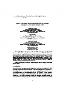
b) Fig. 1. Duplex and time-extended duplex comparison. a) The fault-free behaviour of both schemes is the same. b) In case of fault, duplex produces ERROR signal and incorrect data (data+ ). On the other hand – time-extended duplex produces ERROR signal and fault symptoms (data++ ) and after a defined delay it produces OK signal and correct data.
The common duplex scheme and a high-level representation of our time-extended duplex scheme are shown in Figure 1. Permanent faults consequences in the time-extended duplex module M1* are detected using the proposed universal shortduration offline test. The block M2 provides online testing of
the block M1*. Transient faults consequences are eliminated by recomputation. This allows to tolerate all permanent, transient, and intermittent stuck-at faults. The construction method for the module denoted M1* is presented in this paper. While the common duplex scheme allows error detection only, our time-extended duplex is errorcorrecting. III.
P ROPOSED OFFLINE T ESTING P RINCIPLE
For the universal short-duration offline testing, we propose a simple test consisting of all-zero and all-one vectors. Also similarly simple (all-zero and all-one) output vectors will be observed at the outputs in a fault-free circuit. When symmetric elements only are used, all faults are propagated without risks of fault masking. Next, the requirement for simple response values (i.e., equal to the test vectors) can be disturbed by usage of inverters. Therefore, the second condition imposed on the circuit is monotonicity [7]. In order to meet both requirements, special gates from which any combinational circuit can be constructed will be proposed. The proposed gates are based on C-elements [8]. Note that such a test eliminates possible problems with reconvergence [9] – all gate-level faults are observable independently of the reconvergence. Next, multiple faults in combinational logic do not affect fault observability and controlability too, since no fault masking is possible. Therefore, the method is natively able to test multiple stuck-at faults. IV.
P ROPOSED G ATES AND T HEIR T ESTING
Probably the most commonly used implementation of a C-element is the semi-static C-element [8], (see Figure 2). Another implementation is the dynamic C-element. We use semi-static implementation for illustration, but in practice, we prefer dynamic C-element, because it is smaller and powerefficient compared to the semi-static one.
”plain” C-elements only – the C-element itself does not constitute a complete set of gates [10]. To construct regular logic with properties of C-element-based designs, the C-element must be modified. The structure used to create C-elementbased regular gates is called generalized C-element [11] (see Figure 2). Next, because monotonicity is required, dual-rail logic will be used. A. Dual-Rail Logic In dual-rail logic [6], one logic value is encoded using two signals. Quasi-delay insensitive (QDI) [8] is a class of asynchronous circuits using dual-rail logic for value propagation and completion detection. This design style was the primary inspiration for the proposed method. B. Generalized C-Element-Based Dual-Rail Gates Combining properties of previously described approaches, C-element-based regular logic gates can be constructed. Any combinational circuit can be constructed using the proposed gates. Every gate in these circuits works in two phases. When the signal denoted as P is asserted, the preset phase is running – C-elements are preset to a specified value. All transitions on input signals A and B should finish during this phase. In the second phase, inputs are evaluated and outputs of both C-elements will stabilise in correct states corresponding to dual-rail AND/NAND behaviour. In Figure 3, the complete proposed AND/NAND gate is shown. During the normal operation (preset and computational phases): Pi = Ei and T1 = 1 and T2 = 0. The combinational logic operation frequency should be comparable to the approaches similar to QDI. E1
P1
AF BF
P
weak
B C
N
weak
P2
T2
AT weak
BT CF
C
A
E2
T1
weak CT
C A 0 0 1 1
B 0 1 0 1
C 0 C C 1
Fig. 2. The generalized C-element – left (the memory element is driven by NMOS and P-MOS parts connected to VCC and GND respectively). Semi-static C-element implementation – center, C-element symbol and 2-input C-element truth table.
The principle of the test is as follows: first, all elements are preset to a selected value, which is then propagated in the whole circuit. If a fault is present at any signal in the circuit, it inhibits the transitions in the path from the fault to the circuit outputs. As indicated in the previous lines, the state-holding Celements allow straightforward fault propagation. However, general combinational circuits cannot be constructed by using
Fig. 3. Dual-rail AND/NAND gate implementation with preset. CT is the output of the AND gate and CF is the output of the NAND gate. Signals E1 and E2 are input enable signals and signals T1 , T2 are only for test purposes. The illustrated implementation is a single-rail AND gate replacement. The single-rail NAND gate replacement differs only in a wire-swap: CT ↔ CF .
The preset phase: P1 = E1 = T1 = 1 and P2 = E2 = T2 = 0. The computational phase: P1 = E1 = 0, T1 = 1, P2 = E2 = 1 and T2 = 0. C. Testing Procedure Stuck-at faults on inputs AT , BT , AF and BF and on enable signals E1 and E2 can be tested in the same way as described for the semi-static C-element in IV, when preset signals are inactive (i.e. P1 = 0, P2 = 1, T1 = 1 and T2 = 0). The
following procedure to test all stuck-at faults at the gates inputs and outputs is proposed: First, all circuit primary inputs and enable signals of all gates are set to 0. In the second step, all inputs and enable signals are set to 1 and finally back to 0. The delay between value changes equals to the circuit propagation time. Values 0, 1 and 0 will be observed on all circuit outputs if the circuit is fault-free. When a fault is detected during this test, it will be detected as an inverted value on the affected outputs. Denote this test as test No. 1. The preset function must also be tested. Next lines will describe how to test signals P1 and P2 and their complements – T1 and T2 . The purpose of the first of the described tests is to test the preset to one function in all gates, using signals P1 and T2 . During the second test, preset to zero is tested using signals P2 and T1 . During the test of the preset signals (and their complements), the gate under test is not transparent. If stuck-at faults at all gate inputs were to be tested at the same time, the gates from higher levels would not propagate the fault symptoms from lower levels. This is the reason why these signals must be tested level-by-level. When gates in one circuit level are under test, the other gates must be set transparent. The levelby-level testing procedure will be called a topological wave test. All s@0 and s@1 fault symptoms can be observed during the topological wave test. The wave test progress for the whole circuit is following: in the first phase, all preset signals are set to inactive state (i.e. P1 = 0, P2 = 1, T1 = 1 and T2 = 0) and all circuit inputs and enable signals are set to 0. This value is then propagated to the circuit outputs (note, that this phase is identical to the last phase of the test No. 1). After the first phase is finished, enable signals E1 and E2 for gates at the first topological level (i.e., gates driven by primary inputs only) stay 0. For gates at higher levels, E1 and E2 are set to 1. Then all circuit primary inputs are set to 1. This will allow value 1 propagation in the whole circuit. If a s@0 fault is present, the path from this fault to the affected outputs will hold the 0 value. Gates at the first level stay intact because they are set to be sensitive only to 0 on the inputs. Now the propagation paths are prepared and gates at the first level are preset to 1 using preset signals P1 and T2 . After the circuit-propagation delay, value 1 should appear on every circuit output. If value 0 preserves, a fault has been detected. After gates at the first level are tested, gates on the next levels will be tested in a topological order in the same way. At first all Ei signals of all gates and the circuit primary inputs are set to 0. Then Ei signals of all gates except of gates on the tested level and the circuit inputs will be set to 1, and finally, signals P1 and T2 of gates on the tested level will be set to 1. After the propagation delay a faulty or correct value can be observed at the circuit outputs. The test will proceed in this order until gates on all levels are tested. Values 0 and 1 should switch regularly on the circuit outputs in well defined time intervals and with delays based on gate depths. This test will be denoted as test No. 2.
After the whole wave test is finished (all circuit levels were tested), another test should be done analogously for signals P2 and T1 . Setting the circuit inputs to 1 and presetting to value 0 will be performed during this test. The last test will be denoted as test No. 3. By concatenating all the tests – test No. 1, test No. 2 and test No. 3 – we obtain the complete test. Our complete test is able to detect all stuck-at faults at a gate-level. The initial part of the test is the same for every circuit, but additionally the test duration depends primarily on the circuit depth (the number of gate levels). Thus, circuits with smaller depths have shorter tests. The worst-case test length is: (2 + (2 · 2k)) · tp ,
(1)
where k is the circuit depth and tp is the circuit propagation time. V.
P ROPOSED D ESIGN M ETHOD
The practical realisation of our time-extended duplex system is presented in Figure 4. As it exploits time-redundancy, the system based on the proposed method is globally asynchronous. The Online check module in Figure 4 can be a singlerail implementation of the combinational logic function. It corresponds to the module M2 in Figure 1, Datapath and Li control modules correspond to the module M1*. Datapath and test control logic module, together with the remaining logic implements the Voter in Figure 1. Voter-testing is not included in the complete short-duration offline test. ACK
ACK
FAULT_DETECT
REQ external control
L2 control
Lk control
TEST 11 10
0 1
in
VALID_DATA (REQ)
Datapath and test control logic L1 control
i1
VCC
0
C
C
C
C
C
C
C
C
C
C
C
C
o1
D
Q
O1
0-
R
oj
1
Datapath delay
TEST_DATA o'1
Online-check
o'j
Fig. 4. Time-extended duplex implementation containing the datapath module constructed using the proposed gates.
A. Error-Correction Principle The presented circuit works as follows: if no fault is detected by the online-checker, the result computed in the Datapath module is stored in the output register (the flipflop in Figure 4) and the VALID_DATA signal is asserted. Conversely, if a fault is detected (signal FAULT_DETECT), the universal short-duration offline test is launched. This test
generates fault-symptoms. These are accumulated in the output register. After the offline test is finished, the circuit recomputes the response using the same inputs as in the first phase. If a fault is detected again, it is corrected using fault-symptoms stored in the output register (only outputs where both tests – online and offline – report the fault presence are corrected). The corrected result is stored in the output register in place of the symptoms. If the fault is not detected again, new – uncorrected – results will be stored. This approach eliminates both transient-fault and permanent-fault effects. Finally, the VALID_DATA signal is set. B. The Datapath Module Construction The Datapath module is based on dual-rail logic, as indicated in Section IV. The dual-rail implementation can be derived from any single-rail implementation in a straightforward way – each single-rail gate is replaced by two complementary gates forming a dual-rail one (see Subsection IV-B). Therefore, the area overhead is approximately doubled. In the next step, denoted as a reduction, the area overhead is minimized. Each signal in the single-rail circuit is represented by two complementary signals when transformed into the dualrail logic. In, e.g., QDI [8], presence of both complementary signals is necessary for completion detection. However, in our approach, no completion detection is needed; complemented signals play just a role of inverters. Therefore, all unnecessary gates in the combinational circuit are removed from the design in the reduction step. Note that the resultant datapath module is monotonic – no inverters are present in the module. The inputs i1 . . . in in Figure 4 correspond to inputs of the original single-rail circuit and their negations, while some inputs polarities can be removed by the reduction. C. The Remaining Logic
VI.
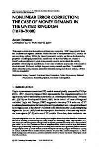
Even though the number of gates after the reduction is less than twice the number of gates in the original circuit, the real overhead is greater, because the proposed gates are larger. The area-overhead based on the number of transistors compared to the TMR overhead is shown in Figure 5. Two-input gatesbased circuits were simulated. More-input gates have better area-overhead ratio compared to the common implementation. Thus, increasing the portion of gates with greater fan-ins is desirable. VII.
R EFERENCES [1] [2]
[4]
[5]
The FAULT_DETECT is the output signal of the fault detection circuit, which is constructed as an OR-tree. The remaining logic located on the right side of the Figure 4 implements the fault-symptom-based error-correction.
[6] [7]
Area overhead compared to TMR [%] of transistors in TMR
180
[8] 160 140
[9] 120 100 80 0
50
100
150
200
[10] [11]
Fig. 5. Area overhead comparison (transistors count) with a common TMR implementation. Dynamic C-elements were assumed.
C ONCLUSIONS
This paper brings the first presentation of a completely new method for a design of error-correcting circuits. Our method combines time- and area-redundancy – the timeextended duplex scheme is proposed. It is based on a special gate design allowing a universal short-duration offline test to be performed to achieve a complete stuck-at fault coverage. Basic properties of the proposed solution were determined using simulations. Experiments have shown, that for majority of the tested circuits, our method reduces the number of gates compared to TMR significantly. However, in terms of the transistors count, the area is comparable to TMR on average. If the circuit depth will be decreased and the average gate fanin increased, our method promises significant savings also in transistors count. Our future work will take this direction. The main disadvantage of our method is that the switching activity rises exponentially when the number of ones and the number of zeroes is not balanced in input vectors. This issue will be explored in the future too.
[3]
A feasible implementation of the global control assumes a 16-state Moore machine, cooperating with a Gray-code counter with (k + 2) states (k is the circuit depth). The level-selector needed for iterations over all circuit levels can be implemented as a counter with n → 1 decoder or by using delay lines.
P RELIMINARY R ESULTS
I. Koren and C. M. Krishna, Fault-Tolerant Systems. San Francisco, CA, USA: Morgan Kaufmann Publishers Inc., 2007. H. Kopetz, “Dependability,” in Real-Time Systems, ser. Real-Time Systems Series. Springer US, 2011, pp. 135–166. V. Nelson, “Fault-tolerant computing: fundamental concepts,” Computer, vol. 23, no. 7, pp. 19–25, July 1990. I. David, R. Ginosar, and M. Yoeli, “Self-timed is self-checking,” Journal of Electronic Testing, vol. 6, no. 2, pp. 219–228, 1995. [Online]. Available: http://dx.doi.org/10.1007/BF00993088 J. Ruan, Z. Wang, K. Dai, and Y. Li, “Design and test of self-checking asynchronous control circuit,” in Integrated Circuit and System Design. Power and Timing Modeling, Optimization and Simulation, ser. Lecture Notes in Computer Science. Springer Berlin Heidelberg, 2007, vol. 4644, pp. 320–329. A. Davis and S. M. Nowick, “An introduction to asynchronous circuit design,” Tech. Rep., 1997. F. J. Hill and G. R. Peterson, Introduction to Switching Theory and Logical Design. New York, NY, USA: John Wiley & Sons, Inc., 1968. J. Sparsø and S. Furber, Principles of Asynchronous Circuit Design: A Systems Perspective, 1st ed. Kluwer Academic Publishers, Boston, 2001. L. Biwei, C. Shuming, and H. Xiao, “Analysis of glitch reconvergence in combinational logic ser estimation,” in Second Asia International Conference on Modeling Simulation, 2008. AICMS., May 2008, pp. 1015–1020. H. Enderton and H. B. Enderton, A mathematical introduction to logic. Academic press, 2001. D. Thompson, “Improved C-element and logic reduction and completion detection circuits,” Jan. 12 2006, wO Patent App. PCT/GB2005/002,412. [Online]. Available: http://www.google.com/patents/WO2006003368A2?cl=en