Figure 1: A pepper model flattened into one large piece with bounded distortion. The 3D object is ... To our knowledge, this is the first method to compute the mesh ... linear manifolds, represented as triangular meshes with irregular ... such a surface may be defined by a mapping between its vertices .... Each base mesh trian-.
Bounded-distortion Piecewise Mesh Parameterization Olga Sorkine
Daniel Cohen-Or
School of Computer Science Tel-Aviv University
Rony Goldenthal
Dani Lischinski
School of Engineering & Computer Science The Hebrew University of Jerusalem
3.0
2.0 1.5 1.0
Figure 1:
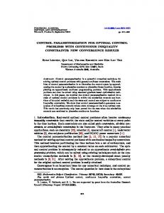
A pepper model flattened into one large piece with bounded distortion. The 3D object is shown on the left with a checkerboard texture demonstrating the low distortion of the parameterization. Seams introduced by our algorithm are shown in red. The middle image shows the flattened surface, visualizing the amount of distortion introduced by the mapping across the mesh. A small region of the flattened mesh is shown on the right.
Abstract
processing [9]. Since in 3D computer graphics surfaces are 2D entities (2-manifolds) embedded in 3D space, a parameterization defines a mapping between regions on the 2D plane and the surface, enabling these operations to be performed almost as easily as if the surface was flat. The surfaces used in computer graphics are very often piecewiselinear manifolds, represented as triangular meshes with irregular connectivity and non-uniform triangle sizes. A parameterization of such a surface may be defined by a mapping between its vertices and a set of points in the plane, such that the connectivity of the mesh induces a planar triangulation. Of course, this is only possible for an open surface (with the topology of a disk). A closed surface of genus zero, such as a sphere, must be first cut open along at least one edge before it can be mapped onto a planar region. Surfaces of higher genus require a larger number of cuts. Ideally, the mapping between the triangulated surface and the planar triangulation should be an isometry, preserving angles and distances. Such a parameterization is area-preserving, so it is optimal for texture mapping, remeshing, and digital geometry processing, since a regular sampling grid with uniform spacing in the parameter domain is undistorted by the mapping onto the surface. Unfortunately, with the exception of developable surfaces, such as a cylinder, general open manifolds cannot be flattened without distortion. Distortion can be reduced by introducing additional cuts (seams) beyond those necessary to make the surface a topological disk. The downside of having too many seams, however, is that they introduce discontinuities into the parameterization. These discontinuities must be explicitly dealt with by the application, which typically slows it down and sometimes results in visible artifacts. Thus, we are faced with two conflicting goals: reducing distortion on the one hand and keeping the seams few and short on the other hand. To achieve our goals, it is usually necessary to split the mesh into several disconnected parts, even though it is already a topological disk. This partitioning results in a piecewise parameterization; the parts are sometimes referred to as charts and their collection is referred to as an atlas [16]. In this paper, we propose a simple and fast method for constructing piecewise parameterizations of irregular triangle meshes. Our approach is guided by two principles: (i) the distortion bounds are controlled, and the method guarantees that the distortion of each
Many computer graphics operations, such as texture mapping, 3D painting, remeshing, mesh compression, and digital geometry processing, require finding a low-distortion parameterization for irregular connectivity triangulations of arbitrary genus 2-manifolds. This paper presents a simple and fast method for computing parameterizations with strictly bounded distortion. The new method operates by flattening the mesh onto a region of the 2D plane. To comply with the distortion bound, the mesh is automatically cut and partitioned on-the-fly. The method guarantees avoiding global and local self-intersections, while attempting to minimize the total length of the introduced seams. To our knowledge, this is the first method to compute the mesh partitioning and the parameterization simultaneously and entirely automatically, while providing guaranteed distortion bounds. Our results on a variety of objects demonstrate that the method is fast enough to work with large complex irregular meshes in interactive applications. CR Categories: I.3.5 [Computer Graphics]: Three-Dimensional Graphics and Realism—Color, shading, shadowing and texture; Keywords: atlas, mesh partitioning, parameterization, surface flattening, texture mapping, 3D painting
1
INTRODUCTION
Low-distortion parameterization of triangulated surfaces is a fundamental problem in computer graphics. Such parameterizations are essential for operations such as texture mapping [2, 4, 10, 13, 14, 16, 19, 26], texture synthesis on surfaces [22, 24, 25], interactive 3D painting [11], remeshing and multi-resolution analysis [1, 5, 12, 23], mesh compression [7, 8, 21], and digital geometry
IEEE Visualization 2002 Oct. 27 - Nov. 1, 2002, Boston, MA, USA 0-7803-7498-3/02/$17.00 © 2002 IEEE
355
All of the methods above may partition complex surfaces into more parts than necessary to obtain a low-distortion parameterization, and, as already mentioned earlier, none of them provides strict bounds on the distortion. Floater [6] embeds an open mesh in the plane by mapping its boundary vertices to those of a predefined convex 2D polygon. The position of each inner vertex is then defined as a convex combination of its topological neighbors, where the weights are set to mimic the cord lengths and the angles between the edges emanating from the vertex. These constraints define a linear system of equations whose solution provably exists, always yielding a valid planar map. However, the predefined planar boundary used by this method may yield significant distortions in the resulting parameterizations, when the parameterized surface is complex and exhibits high curvatures. L´evy and Mallet [13] extend Floater’s approach by defining a set of non-linear constraints on the mapping that ensures local orthogonality and even spacing of isoparametric curves. The non-linear system can be reduced to a set of linear systems by fixing one of the two coordinates in the plane and solving a linear optimization problem for the other. Their method also allows to interactively specify “important” regions on the surface, which have higher priority and are less distorted in the parameterization. Haker et al. [10] propose an interesting method to embed a closed surface onto a sphere by computing a conformal mapping which preserves angles of the mesh triangles. Another work by Sheffer and de Sturler [20] also concentrates on preserving angles of the mesh while mapping it onto the 2D plane. The mapping is defined in terms of the angles only, and an optimal solution is proven to exist. However, these methods still impose high distortion on highly curved surfaces and may cause global self-intersections. To cope with the distortion problem, Sheffer [19] proposes to introduce seams into the surface, computed by a minimal-spanning-tree algorithm. Since cutting the surface at the regions of high curvature reduces the Gaussian curvature, the seams improve the quality of the mapping. The self-intersections are detected in a post-process, and the parameterization needs to be recomputed to eliminate them, adding to the computational cost of the solution. A recent work by Zigelman et al. [26] analytically finds an embedding of an open mesh in the plane by a multi-dimensional scaling (MDS) method that optimally preserves the geodesic distances between mesh vertices. As in [13, 20], this approach does not require forcing the mapping of the surface boundary, which allows better parameterizations to be generated. Like other global optimization-based techniques, this method is computationally expensive and does not guarantee prevention of self intersections. Bennis et al. [2] propose a piecewise flattening method for freeform parametric surfaces (such as B-spline patches). First, a userspecified isoparametric curve on the surface is embedded in the plane with geodesic curvature preservation. Next, their method proceeds to iteratively unfold neighboring curves, until a distortion threshold (involving cord length and angle distortion) is reached. The user selects the next curve on the remaining part of the surface, and the process repeats itself. To our knowledge this is the only technique so far to produce a bounded distortion parameterization. Our approach is similar to that of Bennis et al. [2] in the sense that we also grow our patches incrementally until no more vertices can be added. However, our method is fully automatic requiring no interactive user input, can handle any triangular mesh, and employs more diverse stopping criteria (see Section 3.4). Another difference is that we measure distortion in a different way that is better suited for triangular meshes, as in [18]. There are also several methods which specifically address the problem of mesh partitioning or segmentation. Mangan and Whitaker [17] extend the watershed algorithm for image decomposition to handle polyhedral surfaces. Li et al. [15] use skeletonization and space sweeping to decompose a given mesh into
mesh triangle does not exceed some preset threshold; (ii) the mesh is cut and partitioned simultaneously with the construction of the parameterization, and not as a preprocess, to the degree necessary for creating patches with bounded local distortion. Starting from a seed triangle each patch is “grown” incrementally, from the inside outward, which allows control over local distortion and also provides a convenient way to check for self-intersections. In each step a new vertex is chosen for flattening, from among the neighbors of already flattened vertices. The vertex selection criteria may include various attributes, such as the distortion caused to the triangles sharing this vertex, local curvature, ratio of patch boundary length to its area, etc. When there are no more vertices that fit the criteria, the patch growth is stopped and a new patch is started. Figure 1 demonstrates the result of applying our method to a model of a pepper. The proposed scheme has several advantages. First, it guarantees a user-specified upper bound on the local distortion. Experiments show that in practice the average distortion value achieved is significantly smaller than the specified bound. Second, the algorithm is fully automatic, partitioning the mesh as necessary in order to comply with the specified distortion bounds. It is guaranteed to produce a valid parameterization without local or global foldovers. Finally, in contrast to most previous parameterization techniques, our algorithm is fast enough to enable working with large complex irregular meshes in interactive applications. However, our approach does not provide the optimal solution, it is greedy and provides no explicit control on the location or the length of the seams. The rest of the paper is organized as follows. In Section 2 we review related work. Our algorithm is described in detail in Section 3. Section 4 presents some results and applications of our method. Section 5 concludes the paper and suggests some topics for future work.
2
PREVIOUS WORK
Many researchers have addressed the problem of computing lowdistortion parameterizations for general surfaces, mainly for texture mapping purposes. We shall briefly survey some of their methods below. For the most part, these earlier works concentrate on minimizing the parameterization distortion and not on the mesh partitioning problem. They either assume that the mesh has already been partitioned, or begin by computing a partitioning of the mesh as a pre-process, based on some heuristic or interactive user input. Each part is then parameterized while minimizing some distortion criterion. It should be noted that while several authors refer to their techniques as “non-distorting”, the resulting parameterizations typically correspond only to a local minimum with respect to the chosen distortion measure, and do not guarantee any strict bounds on the distortion. In contrast, our method computes the partitioning of the mesh simultaneously with surface flattening, introducing seams and cuts only as necessary to produce a mapping with distortion strictly below a specified bound. Maillot et al. [16] partition the mesh into regions by bucketing faces based on their normals, followed by merging together adjacent buckets with similar normals and directions of maximal curvature. Each region is then flattened and the resulting parameterization is improved by numerically minimizing a distortion energy functional. Eck et al. [5] and Lee et al. [12] partition the mesh by constructing a coarse base mesh, using mesh simplification [12] or growing Voronoi-like tiles on the surface [5]. Each base mesh triangle defines a separate parameter domain for a corresponding cluster of triangles in the original mesh. The embedding is computed using harmonic maps ([12] add a subdivision-based smoothing step). Sander et al. [18] begin by partitioning the mesh into relatively flat regions (similarly to [16]). They define their own “geometric stretch” measure, and employ relaxation to minimize it.
356
(a)
has two vertices that have already been mapped onto the plane, and one free vertex. We choose the “best” vertex among all free vertices adjacent to the front, and unfold it onto the plane along with the triangles incident to it and sharing an edge with the patch front. The ranking of the free vertices is determined based on several criteria (see Section 3.4), the most important of which is the distortion. More specifically, a vertex can be embedded only if the distortion caused to each of the newly-flattened triangles does not exceed the predefined threshold. The added triangles are also checked for intersections with the planar patch (see Section 3.5), and if an intersection is detected, the vertex is discarded from the current patch. When no more vertices can be added to the current patch (either due to distortion or intersections), the algorithm selects a new seed and starts growing a new patch. For efficiency, the grades of the free vertices are kept in a priority queue. At each step we take the vertex with the highest grade off the queue and map it onto the plane (Section 3.3). We then compute the grades of all free neighbors of the newly-added vertex and add them into the priority queue. In addition, we update the grades of the free vertices adjacent to the flattened vertex, which are already present in the priority queue (Section 3.4).
(b)
Figure 2:
Flattening of a cylindrical model. In (a), the parameterization created by our algorithm is visualized. The seam line is marked in red. In (b) we show that partitioning such a mesh using normal-based bucketing [16] results in sixteen patches.
topologically and geometrically homogeneous components. Since these segmentation methods are driven by other applications, such as shape-based retrieval, hierarchical object representation, morphing, etc., they are not particularly suited for parameterization. For instance, they do not necessarily produce topological disk patches, which is a basic requirement for a global flattening algorithm. In contrast, our method partitions the mesh while computing the parameterization, so the partitioning is driven by the specific goal of producing a bounded-distortion parameterization. Our method aims at defining large patches whenever possible. For example, the surface of the model shown in Figure 2 is developable and is flattened into a single patch by our method, while partitioning the mesh using normal-based bucketing [16] results in sixteen patches. Recently, several new related works have appeared [4, 8, 14]. Desbrun et al. [4] derive several intrinsic distortion measures to flatten a single patch, without addressing the partition issue. Gu et al. [8] iteratively cut the mesh to produce a single patch and employ the method of [18] to flatten it, with some specific restrictions on the boundary, driven by the application of regular geometry resampling. L´evy et al. [14] partition the mesh by extracting feature curves on the surface and applying simultaneous region growing scheme, and then parameterize each patch while minimizing angle distortion in the least squares sense. None of the above methods guarantee strict distortion bounds. For example, L´evy et al. [14] explicitly state that when the distortion of a flattened patch exceeds a user-defined bound, the patch is subdivided into several parts and reparameterized.
3
3.2
We measure the distortion caused to a triangle using the singular values of the Jacobian of the affine transformation between the original 3D triangle and its counterpart in the plane. The derivation below closely follows that of Sander et al. [18]. Let T = ∆q1 q2 q3 be the triangle in 3D and T 0 = ∆p1 p2 p3 the triangle in 2D, where pi = (si ; ti ). Let S : R2 ! R3 be the (uniquely defined) affine mapping, such that S(pi ) = qi . Denote by hp1 ; p2 ; p3 i = ((s2 s1 )(t3 t1 ) (s3 s1 )(t2 t1 ))=2 the area of ∆p1 p2 p3 . Then, S is given by S(p) =
hp p2 p3iq1 + hp p3 p1 iq2 + hp p1 p2 iq3 hp1 p2 p3 i ;
;
;
;
;
;
;
;
;
and the partial derivatives of S are: Ss =
BOUNDED DISTORTION FLATTENING
St
=
∂S ∂s
∂S ∂t
=
=
q1 (t2
q1 (s3
t3 ) + q2 (t3 t1 ) + q3 (t1 2 hp1 ; p2 ; p3 i
t2 )
s2 ) + q2 (s1 s3 ) + q3 (s2 2 hp1 ; p2 ; p3 i
s1 )
:
The singular values of the 3 � 2 Jacobian matrix [Ss St ] are:
In this section, we describe our parameterization algorithm. We begin with a brief overview of the proposed framework and then elaborate on its different components.
3.1
The Distortion Metric
γmax =
Overview γmin =
Our algorithm is an iterative procedure that incrementally flattens the mesh surface by growing patches around seed triangles, until some termination criterion is reached. We define as active an edge separating between a triangle that has already been added to the patch (flattened) and one that hasn’t. The collection of all active edges of a patch at any given moment is referred to as the patch front. Our algorithm grows patches by iteratively selecting a new vertex adjacent to the patch front and adding it to the patch. The above process explicitly makes sure that none of the triangles are distorted above the specified threshold. The first triangle of a patch, referred to as the seed triangle, is randomly selected and embedded on a plane without any distortion. Its three edges define the initial patch front. In each subsequent iteration, the algorithm examines all the triangles adjacent to the front. Each such triangle
r � 1 2
(a + c) +
r � 1 2
(a + c)
p
p
(a
c)2 + 4b2
(a
c)2 + 4b2
�
� ;
where a = Ss � Ss ; b = Ss � St ; c = St � St . The values γmax and γmin represent the largest and the smallest scaling caused to a unit length on the plane by the mapping S. Sander et al. [18] take the root-mean-square of the two values as the L2 metric and γmax as the L∞ metric. Since for the purpose of measuring geometric distortion, stretching and shrinking should be treated the same, we use the following expression as our distortion metric: � � D T ; T 0 = max γmax ; 1=γmin : Note that D (T ; T 0 ) � 1, and the equality holds if and only if T and T 0 are isometric.
357
(a)
(b)
(c)
Figure 3:
Embedding a vertex V . In (a), the patch on the 3D surface is shown in dark green and the red vertex is V , the top vertex of the triangles T 1 and T2 that share an edge with the patch front. In (b), the flattened patch is shown, with the triangles T1 and T2 unfolded separately into t1 and t2 . Two planar positions for V are obtained: v1 and v2 . In (c), v1 and v2 are unified into v, and the vertex is added to the patch.
3.3
Embedding a Single Vertex
tation information that may be available. The weight of each feature should be determined by the specific application that uses the parameterization. For instance, in texture mapping, visible seams between the patches are an undesirable artifact, and therefore minimizing the boundary length should be given more weight. For a 3D painting application, the most critical factor is low and homogeneous distortion of the parameterization, while seams can be tolerated.
As stated above, in each step of the flattening procedure, we attempt to embed a free vertex V that is adjacent to the front. Let T1 ; T2 ; : : : ; Tk be the triangles incident to V that share an edge with the front (thus, V is their top vertex, see Figure 3(a)). We would like to map V to a point v in the plane, so as to minimize the maximal distortion caused to the triangles Ti . The optimal position v is found using a local relaxation technique. A faster alternative that performs well is to compute k candidate positions in the plane, each obtained by rigidly unfolding each of the triangles Ti separately. The point v is then obtained as the weighted average of the candidate positions, where the weights are proportional to the distortion associated with the flattened neighbors of the triangles (Figure 3(b–c)). Note that except for certain degenerate cases, this choice of mapping prevents triangle-flipping. We check global and local self-intersections when the vertex is chosen to be added to the patch. In this embedding strategy each vertex has only one mapping to the plane, simply because once a vertex is added to the patch, it cannot be flattened again in a different location. However, sometimes the parameterization can benefit from forcing cuts in the surface, where the vertices on the cuts have two or more mappings to the plane. For example, if a cylinder is cut along the direction of its central axis, it can be unfolded to the plane in one piece (see Figure 2(a)). To detect such cases, once the patch growth is complete, we traverse the front and look for adjacent unmapped triangles whose top vertices are already mapped in some other regions of the patch. These triangles can be added to the patch by assigning a second location to their top vertex (thus introducing a seam).
3.4
(a)
(b) Figure 4:
Change of a vertex grade. In (a), the vertex V has two incident triangles T1 and T2 , and its plane position and grade is calculated based on these two triangles. In (b), the vertex U is added to the patch, and as a result, the triangle T3 also becomes incident to V , so that the grade of V must be updated.
Local Criteria for Vertex Embedding
Note that the grade given to a vertex can change during the process of patch growing. Figure 4 illustrates a situation where the vertex V is given an initial grade based on the two triangles that are incident to it. But after embedding another vertex, an additional triangle becomes incident to V , and thus the position of V on the plane is altered and the grade of V must be recomputed. Grades changes are local, since embedding a vertex can affect only its topological neighbors. By Euler’s formula, the average valence of a vertex is six. Thus on average up to six grades are recomputed each time a vertex is added to the patch, but in practice grade changes are much more rare.
As explained in Section 3.1, we assign a grade to each free vertex adjacent to the patch front, and select the vertex with the highest grade at each iteration. The grade is a non-negative real number, comprising various factors with different importance weights. The main factor is the maximal distortion caused to the triangles adjacent to the vertex. If this value is above the predefined threshold, the vertex is given a grade of zero, and thus cannot be flattened. Another important issue is the boundary length of the resulting partition. We would like to keep it as small as possible and prevent the creation of thin long patches (strips). This may be done by bounding the ratio between the area of the patch and the squared length of the boundary. Vertices that increase this ratio are given a lower grade, and thus the algorithm strives to grow round patches with smooth boundaries (see Figure 12). This ratio can also be incorporated as a stopping condition: when adding any vertex to the patch results in an area/perimeter ratio greater than some threshold, the patch growth is stopped. Additional criteria that can be involved in the grade calculation are crease angles or ridge lines on the surface and other segmen-
3.5
Preventing Self-intersections
There are two types of self-intersections that must be prevented: local and global ones. A local self-intersection, also called faceflipping, occurs when the triangle newly added to the patch, “folds over” the patch, and the cyclic order of its vertices is reversed with respect to the original 3D triangle. Such triangles are sometimes
358
by first projecting the patches onto a plane followed by relaxation. More specifically, given a patch we first orthographically project it onto the plane orthogonal to the average normal of the patch. Next, an iterative relaxation method is applied to minimize the distortion of the initial guess. We have tested the minimization of the metric proposed in [16] (edge and area stretch) and the metric of [18], which is closely related to the Jacobian metric used by our algorithm. Figures 2 and 10 compare the results produced by the scheme described above with those produced by our method. When the surface is sufficiently complex, normal-based bucketing produces an unnecessarily large number of patches. In simpler cases, this partition may produce patches that seem more natural to a human observer, but they are not optimal in the sense of distortion minimization. Moreover, it should be emphasized that the normal-based bucketing method might yield invalid patches in the sense that their projection contains self-intersections, as demonstrated in Figure 11.
Figure 5:
Checking local self-intersections and preventing triangle flipping. The vertex v is incident on two triangles, whose neighbors in the patch are t 1 and t2 . The half-planes Π1 and Π2 are bounded by lines that support the bases of t1 and t2 , respectively. Local self-intersection is prevented by ensuring that v 2 Π 1 \ Π2 .
referred to as having a negative area, and global relaxation techniques (e.g., [13, 16, 18]) use high penalties to prevent this kind of self-intersection. In our algorithm, we take care of triangle flipping by ensuring that the position of the top vertex of each added triangle is located locally “outside” the patch, as shown in Figure 5. Global self-intersections occur when distant parts of the patch cross each other. This type of self-intersection is much harder to track in global embedding techniques and usually it is not addressed. In fact, it can only be detected in a post-process, as done by Sheffer and de Sturler [20]. In our algorithm, since the flattened patch is grown incrementally, we can make sure that each added triangle does not cross the rest of the patch. It is enough to merely test for intersection with the boundary of the patch, since the patch is simply-connected, and each added triangle has a common edge with the boundary. To efficiently perform this test, we insert the boundary triangles of the flattened patch into a spatial partitioning data structure. In the current implementation, we use a regular grid partition, which allows us to locate the boundary triangles that can potentially intersect the new triangle in near-constant time.
4
RESULTS AND APPLICATIONS
We have implemented our algorithm in C++ and tested it on a variety of 3D meshes. Various statistics pertaining to the different tests are summarized in Table 1. Although our code has not been optimized, the running times are rather small when using the fast approximation of optimal vertex position (described in Section 3.3). Large models, such as the 100K triangle Venus, or the 40K triangle Horse (both shown in Figure 12), are flattened in 9 and 4 seconds, respectively. The 1300 triangle Lamp model is flattened in less than a second. All times were measured on a 1.0 GHz Pentium III CPU. Figure 12 shows the three models above with a checkerboard texture map in order to visualize the quality of the parameterizations: it can be seen that the checkerboard pattern is not visibly distorted by the mapping. Each patch is shaded using a different color to visualize the partitioning performed by our method in order to achieve this low-distortion parameterization. Table 1 reports the distortion bound given to our algorithm along with the actual mean distortion value achieved in each case (weighted by the areas of the triangles in 3D). The table also reports the seam length (divided by the sum of the edge lengths in the mesh) and the running times. Figure 6(a) shows the result of flattening the pepper model (11K polygons). Our algorithm embeds the surface into a single patch when given a distortion threshold greater than 1.5. Figure 6(b–d) shows three different embeddings, corresponding to distortion thresholds of 1.5, 2.0 and 3.0, respectively. For comparison, we have also implemented a normal-based bucketing partitioning scheme, which partitions the surface into patches consisting of adjacent triangles with similar normals, as in [16, 18]. The parameterization of the patches is then computed
Figure 7:
Examples of texture mapping using our parameterization. The bound on the distortion of the parameterization guarantees that the texture is mapped onto the surface without visible stretching or shearing.
359
(a) 3.0
2.0 1.5 1.0
(b)
(c)
(d)
Figure 6:
(a) The pepper model (11K polygons) flattened by our algorithm with a distortion bound of 1.5. (b)–(d) Different flattenings of the pepper model generated by our algorithm with three distortion thresholds: 1.5 (b), 2.0 (c) and 3.0 (d). The actual local distortions are visualized using pseudocolor.
rameterization might cause smooth constant-width strokes made by the user to look bumpy and curvy. Therefore, it is essential to keep the local distortion of the parameterization low. Discontinuities, on the other hand, do not pose a problem to the paint program, which draws the stroke in the parameter domain of one region until reaching a boundary, and then continues the drawing operation in the adjacent patch. Such a transition will not be noticeable to the user provided that the distortion on both sides of the seam is similar (and low). However, partitioning the mesh into a small number of patches is still desirable, since the corresponding texture images are more coherent, lending themselves better to mip-mapping and compression.
Another application where a guaranteed distortion bound is vital, is compression of texture coordinates for textured 3D meshes. In [21], we proposed a compression method that avoids explicit encoding of the (u; v) coordinates altogether by warping the original texture image. The 3D surface is flattened onto the 2D plane, and the texture is re-mapped onto the planar embedding using the original (u; v) coordinates, which creates a warped texture image. The decoder retrieves the (u; v) coordinates by flattening the mesh onto the warped texture. The flattening algorithm must be non-distorting to preserve the texture data and prevent undersampling or redundant oversampling. As mentioned above, to bound the distortion, seams sometimes must be introduced to the parameterization. However, the length of the seams should be as small as possible, since they could create artifacts when remapping the warped texture onto the surface using mip-mapping. Figures 9(a–b) show the twisted cone model textured with an image. Figure 9(c) shows the two warped textures mapped into the embeddings of the cone.
Figure 8: Two styles of graffiti over the statues of David and Venus. The drawings were manually created by 3D painting using our parameterization. Note that the strokes are not distorted, although they cross different patches of the underlying parameterization. Two important applications of non-distorting parameterization are texture mapping and 3D painting (see Figures 7 and 8). Figure 8 was generated by the Deep Paint 3D tool [3], which was given the parameterization computed by our method. Such 3D painting applications provide the user the ability to draw directly on the 3D model surface [11]. When the user is painting on a certain polygon of the surface, the brush strokes are registered on the corresponding 2D polygon in the plane, computed by our parameterization. The strokes are displayed on the 3D surface using texture mapping, so that the parameterization is hidden from the user, creating the impression of painting directly on the 3D surface. A distorting pa-
360
(a)
(b)
(c)
Figure 9:
The results of the texture warping. (a) The textured twisted cone model. (b) The twisted cone consists of triangles of different sizes. (c) The warped texture mapped onto the mesh embedding. The non-distorting parameterization assures proper texture sampling (re-texturing).
Model
Size
Venus David Horse Pepper Knot Star cylinder Lamp
100K 47K 40K 11K 6K 2K 1.3K
Our alg. (fast approximation)
Avg 1.03 1.05 1.04 1.04 1.11 1.0 1.08
Len (#p) 0.062 (227) 0.177 (1340) 0.073 (141) 0.034 (1) 0.088 (33) 0.003 (1) 0.108 (19)
Time 9 6 4 1.3 0.8 0.3 0.2
Our alg. (local relaxation)
Avg 1.04 1.07 1.06 1.04 1.14 1.0 1.11
Len (#p) 0.045 (157) 0.155 (1058) 0.063 (108) 0.036 (1) 0.087 (27) 0.003 (1) 0.092 (14)
Time 152 96 49 16 6 16 2
Global relaxation
Avg 1.18 1.22 1.14 1.16 1.21 1.15 1.14
Len (#p) 0.047 (555) 0.198 (3067) 0.070 (477) 0.021 (6) 0.086 (35) 0.050 (16) 0.100 (24)
Time 2523 363 300 93 43 2 11
Table 1: Summary of the results of our method with and without local relaxation versus global relaxation with the Jacobian metric. Size stands for the number of polygons of the models; Avg is the average distortion, weighted by the triangle area; Len is the seam length, normalized by the total edge length; #p is the number of patches. The running time is measured in seconds. We used the distortion threshold of 1.5 for when running our algorithm, except for the Knot model, for which we used 2.0. The statistics were gathered on a 1.0 GHz Pentium III CPU with 512MB RAM.
(a)
(b)
3.0
Figure 11:
Example of self-intersection in normal bucketing partition. In (a), the pink patch is a ”spiral” patch. Its normals face almost the same direction (maximum angle between two normals in the patch is 36Æ ). In (b), the result of projecting the patch onto the plane orthogonal to the average normal is shown.
2.0 1.5 1.0
(a)
seams into the parameterization. Seams have the following disadvantages in the context of re-texturing: (i) they introduce visual artifacts when mip-mapping is used, since the texels that map onto adjacent locations on the object are not adjacent in the planar embedding, if separated by a seam; (ii) vertices on the seams must be assigned more that one pair of 2D coordinates, requiring more storage to represent the parameterization; (iii) the texture atlas is less coherent, making it less compressible. Our approach is willing to tolerate a small, strictly bounded, amount of distortion in exchange for larger, more coherent, patches, and shorter seam lengths. The key point in our technique is that it flattens the mesh based on a local criterion. The advantage of such an approach is that it permits the flattening process to shape the patches as necessary in order to comply with the distortion bounds. Global techniques require the patches to be determined a priori, so there is no explicit control on the maximum distortion that the partition imposes. The disadvantage of our approach is that it is greedy and provides no explicit control on the location or the length of the seams. In summary, since the least amount of distortion that a global relaxation scheme is able to achieve depends on the partition of the mesh, a priori decomposition cannot support pre-specified distor-
(b)
Figure 10:
(a) The knot model partitioned and textured by our method (top) and two of its patches colored by the distortion value. (b) The same model partitioned by normal bucketing and parameterized by global relaxation. Some stretching of the texture is noticeable in the purple patch near the border with the green one. This is supported by the measurements in Table 1.
5
DISCUSSION AND CONCLUSIONS
Our technique is best suited for applications whose main requirement on the parameterization is low distortion. In addition to the applications discussed above, such parameterizations are essential for re-texturing applications. One example, demonstrated above, is texture-warping for efficient texture coordinate encoding [21]. Another example is resampling a solid texture across the surface into a 2D textured atlas, in order to display the textured object using standard 2D texture mapping hardware. Of course, a piecewise parameterization with zero distortion may be obtained by simply embedding each mesh triangle as a separate patch, or by flattening triangle strips. However, such an approach would introduce long
361
Figure 12:
Three models partitioned and parameterized by our algorithm: Horse (left), Venus (middle) and Lamp (right).The checkerboard texture pattern visualizes the lowdistortion nature of our parameterization. Each patch corresponds to a checkerboard with a different color.
tion bounds. In contrast, our method is able to comply with strict upper bounds on the distortion by simultaneously computing the partitioning and the parameterization. Moreover, the local nature of our method offers an easy way to avoid self-intersections. The results of the flattening depend on the selection of the seed triangle. In the future, we would like to gain a better understanding of how the seed selection affects the parameterization. This is related to another research avenue: our algorithm attempts greedily to enlarge the current patch as much as possible, without taking into consideration the shape of the following patches. We would like to eliminate this effect, and to obtain a local technique that computes a piecewise parameterization with some global properties. Finally, in this paper we measure distortion by the Jacobian-based metric presented in Section 3.2. However, our approach is merely a framework into which other metrics could be incorporated, so long as it is fairly reasonable to find the functional’s minimum. This can include, for example, a consideration of some feature detection input.
[9] Igor Guskov, Wim Sweldens, and Peter Schr¨oder. Multiresolution signal processing for meshes. In Proceedings of SIGGRAPH 99, pages 325–334, August 1999. [10] Steven Haker, Sigurd Angenent, Allen Tannenbaum, Ron Kikinis, Guillermo Sapiro, and Michael Halle. Conformal surface parameterization for texture mapping. IEEE Transactions on Visualization and Computer Graphics, 6(2):181– 189, April–June 2000. [11] Pat Hanrahan and Paul E. Haeberli. Direct WYSIWYG painting and texturing on 3D shapes. In Proceedings of SIGGRAPH 90, pages 215–223, August 1990. [12] Aaron W. F. Lee, Wim Sweldens, Peter Schr¨oder, Lawrence Cowsar, and David Dobkin. MAPS: multiresolution adaptive parameterization of surfaces. In Proceedings of SIGGRAPH 98, pages 95–104, July 1998. [13] Bruno L´evy and Jean-Laurent Mallet. Non-distorted texture mapping for sheared triangulated meshes. In Proceedings of SIGGRAPH 98, pages 343–352, July 1998. [14] Bruno L´evy, Sylvain Petitjean, Nicolas Ray, and J´erˆome Maillot. Least squares conformal maps for automatic texture atlas generation. In Proceedings of SIGGRAPH 2002. [15] Xuetao Li, Tong Wing Woon, Tiow Seng Tan, and Zhiyong Huang. Decomposing polygon meshes for interactive applications. The 2001 ACM Symposium on Interactive 3D Graphics, pages 35–42, 243, March 19-21 2001.
Acknowledgements This work was supported in part by the Israel Science Foundation founded by the Israel Academy of Sciences and Humanities, by the Israeli Ministry of Science and by a grant from the German Israel Foundation (GIF). We would like to thank Ronen Gvili, Roman Manevich and Adi Karol for helping us developing parts of the code, and Alla Sheffer and Gershon Elber for reviewing an early version of this work.
[16] J´erˆome Maillot, Hussein Yahia, and Anne Verroust. Interactive texture mapping. In Proceedings of SIGGRAPH 93, pages 27–34, August 1993.
References
[19] Alla Sheffer. Spanning tree seams for reducing parameterization distortion of triangulated surfaces. In Shape Modelling International, 2002. to appear.
[17] A. P. Mangan and R. T. Whitaker. Partitioning 3D surface meshes using watershed segmentation. IEEE Transactions on Visualization and Computer Graphics, 5(4):308–321, October - December 1999. [18] Pedro V. Sander, John Snyder, Steven J. Gortler, and Hugues Hoppe. Texture mapping progressive meshes. In Proceedings of SIGGRAPH 2001, pages 409– 416, August 2001.
[1] Pierre Alliez, Mark Meyer, and Mathieu Desbrun. Interactive geometry remeshing. In Proceedings of SIGGRAPH 2002.
[20] Alla Sheffer and Eric de Sturler. Parameterization of faceted surfaces for meshing using angle based flattening. Engineering with Computers, 17(3):326–337, 2001.
[2] Chakib Bennis, Jean-Marc V´ezien, and G´erard Igl´esias. Piecewise surface flattening for non-distorted texture mapping. In Proceedings of SIGGRAPH 91, pages 237–246, July 1991.
[21] Olga Sorkine and Daniel Cohen-Or. Warped textures for UV mapping encoding. Eurographics 2001. Presented as a short paper.
[3] Deep Paint 3D. Right Hemisphere Ltd., www.righthemisphere.com.
[22] Greg Turk. Texture synthesis on surfaces. In Proceedings of SIGGRAPH 2001, pages 347–354, August 2001.
[4] Mathieu Desbrun, Mark Meyer, and Pierre Alliez. Intrinsic parameterizations of surface meshes. In Eurographics 2002 conference proceedings.
[23] J. Vorsatz, C. R¨ossl, Leif P. Kobbelt, and Hans-Peter Seidel. Feature sensitive remeshing. Computer Graphics Forum, 20(3):393–401, 2001.
[5] Matthias Eck, Tony DeRose, Tom Duchamp, Hugues Hoppe, Michael Lounsbery, and Werner Stuetzle. Multiresolution analysis of arbitrary meshes. In Proceedings of SIGGRAPH 95, pages 173–182, August 1995.
[24] Li-Yi Wei and Marc Levoy. Texture synthesis over arbitrary manifold surfaces. In Proceedings of SIGGRAPH 2001, pages 355–360, August 2001.
[6] Michael S. Floater. Parametrization and smooth approximation of surface triangulations. Computer Aided Geometric Design, 14(3):231–250, 1997.
[25] Lexing Ying, Aaron Hertzmann, Henning Biermann, and Denis Zorin. Texture and shape synthesis on surfaces. In Rendering Techniques 2001: 12th Eurographics Workshop on Rendering, pages 301–312. Eurographics, June 2001.
[7] Craig Gotsman, Stefan Gumhold, and Leif Kobbelt. Simplification and compression of 3d meshes. In Proceedings of the European Summer School on Principles of Multiresolution in Geometric Modelling (PRIMUS), Munich, August 2001.
[26] Gil Zigelman, Ron Kimmel, and Nahum Kiryati. Texture mapping using surface flattening via multidimensional scaling. IEEE Transactions on Visualization and Computer Graphics, 8(2), April–June 2002. to appear.
[8] Xianfeng Gu, Steven J. Gortler, and Hugues Hoppe. Geometry images. In Proceedings of SIGGRAPH 2002.
362