Maya Gokhale, William Holmes, Andrew Kopser, Sara. Lucas, Ronald Minnich, and Douglas Sweely. Supercomputing Research Center. Daniel Lopresti, Brown ...
Building and Using a Highly Parallel Programmable Logic Array Maya Gokhale, William Holmes, Andrew Kopser, Sara Lucas, Ronald Minnich, and Douglas Sweely Supercomputing Research Center Daniel Lopresti, Brown University
W
ith a $13,000 two-slot addition called Splash, a Sun workstation can outperform a Cray-2 on certain applications. Several applications, most involving bit-stream computations, have been run on Splash, which received a 1989 Gordon Bell Prize honorable mention for timings on a problem that compared a new DNA sequence against a library of sequences to find the closest match. In essence, Splash i s a programmable linear logic array that can be configured to suit the problem at hand; it bridges the gap between the traditional fixed-function VLSI systolic array and the more versatile programmable array.’.’ As originally conceived, a systolic array is a collection of simple processing elements, each with a fixed, data-independent function, along with a one- or two-dimensional nearest-neighbor communication pattern.3 The local nature of the communication gives the systolic array a high communications bandwidth, and the simple, fixed function gives a high packing density for VLSI implementation. However, since the function is built in, the application space of a particular systolic array is rather limited. Recognizing the benefit to be gained from a more flexible base for systolic algorithm implementation, H. T. Kung and colleagues January 199 I
Construction of real hardware and feedback from real users contributed to Splash’s design, development, and success. For certain patternmatching applications its price/performance ratio is unmatched.
built the Warp array,’ a linear array in which each cell i s a powerful very-large-instruction-word processor. Currently, a two-dimensional array of custom 32-bit processors is being built jointly by Intel and Carnegie Mellon University.‘ Like the simple fixed-function systolic 0018-916?/91/1000-0081~01.0~~ G 19Y1 I t L E
array, the linear array of chips comprising Splash is programmed at a very low level. A hardware implementation of the desired algorithm must be synthesized. Unlike the fixed-function systolic array, the “hardware” can be reprogrammed and loaded with new algorithms. This is made possible by using field-programmable gate arrays (FPGAs) as the chips of the linear array. Unlike the programmable systolic array, each stage of linear array does not have an instruction set architecture. Rather than processors with a fixed instruction set, a stage contains several hundred “configurable logic blocks,” each of which can be configured at the gate level to compute certain sorts of Boolean functions. There is no fixed number of systolic cells in the Splash array. The amount of logic i n each cell determines the number of systolic cells per chip and therefore the number of cells in the array. Typical applications have eight or 16 systolic cells per chip. This gate-level programmability enables high-speed execution of algorithms, since only necessary circuitry executes. Systolic and parallel algorithms implemented at the gate level on Splash have achieved speedups of up to 330 over one Cray-2 processors; speedups greater than 10 times are achieved routinely.
81
8-megabyte VSB staging memory
Host
A
Xilinx control chips
Memory
Memory
Memory
Memory
Memory
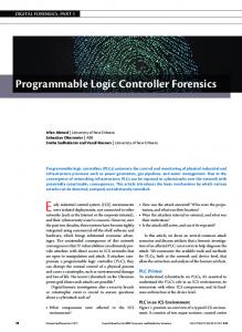
Figure 1. The 32-stage linear array.
Overview of Splash The Splash design was motivated by a systolic algorithm for DNA pattern matching.6 From the outset, the application domain has focused on non-floating-point applications such as pattern matching. Many pattern-matching applications must recognize when two sequences are similar, even though they may not be identical. Examples include speech recognition, data retrieval, and genetic analysis.’ The Splash architecture is suited to one-dimensional pattern matching. A two-dimensional implementation with similar FPGA technology has been built by Digital Equipment Corporation Paris Research Labs.* The design of a prototype was begun in September I988 at the Supercomputing Research Center. In June 1989, Splash was released to the S R C user community. Operational at that time were five Splash systems, the Logic Description Generator (LDG) language, and the Trigger symbolic debugger. Currently, 16 Splash arrays are in use at SRC, Brown University, and elsewhere.
System. Splash consists of two boards, the first containing the linear array and the second containing a dual-ported memory card. The two boards reside in two VME (Versabus modified for Eurocard) slots of a Sun-3 or Sun-4 workstation (see Figure 1). The Splash logic-array board holds 32 Xilinx 3090 programmable gate arrays’ and 32 memory chips. Two additional Xilinx chips are used for bus control. The logic array card connects to the Sun VME bus for control and the Sun VMESubsystem Bus (VSB) for data I/O. The associated 82
dual-ported memory card connects to the Sun VME bus for data initialization and retrieval and to the Sun VSB bus for data U0 to and from the logic array.
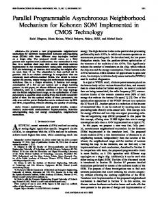
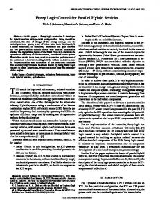
Programming. Splash is programmed by specifying the logic functions and interconnections of each of 320 configurable logic blocks (CLBs) and 144 input/output blocks (IOBs) on each of the 32 chips. A Xilinx 3090 FPGA contains a 20 x 16 grid of CLBs surrounded on the perimeter by a single layer of IOBs (Figure 2). A CLB has a combinatorial logic section, two D flipflops, and an internal control section. The CLB can be configured to generate any function of five variables, any two functions of four variables (see Figure 3), or some functions of up to seven variables. The IOBs provide the interface between external package pins and the internal logic. Each IOB has input and output buffers, which include both registered and direct data paths. Each Xilinx chip is programmed at the gate level using the Logic Description Generator language. LDG is a computeraided design tool developed at SRC, with language constructs to describe and replicate systolic cells and to place the cells on achip. Parameterizedcell descriptions may be written, providing a functionality similar to the VHDL (VHSIC hardware description language) generate command. Splash designs are debugged using the Trigger symbolic debugger, also developed at SRC. Trigger is similar to a software debugger, with user-definable procedures and local variables. The values of specific locations on the gate array can be examined symbolically. The array can be single stepped or stepped in burst mode. Inter-
rupts can either be ignored or can invoke a Trigger procedure. LDG and Trigger permit rapid design turnaround time that is more comparable to software than hardware redesign. With LDG, it takes only a few keystrokes to significantly modify a chip design, which can be easily tested with Trigger. These design tools, plus the fact that a design can be loaded on the board in half a second, make it easier to generate and test a new chip design on Splash hardware than to simulate several different designs before committing to hardware.
Hardware development Designing and developing Splash required numerous decisions and trade-offs in defining the hardware (and the LDG and Trigger, as described in later sections). The systolic array, as first envisioned, was to consist of many stages connected in a one-dimensional array. Each stage was to have three components: a Xilinx FPGA, local memory, and a floating-point chip. The initial design called for dual-ported local memory so that the host could directly access all the memory on the board. For the prototype, we planned to develop a simple one-board system that would plug into a Sun workstation, communicating with the Sun CPU over the VME bus. Because we opted for a single-board system, space became the constraining factor. Thirty-two FPGA/SRAM pairs fit nicely on a 9U x 400-millimeter card but left no room for floating-point chips. Since the application driving the design did not require floating-point manipulation, we eliminated floating-point chips from the COMPUTER
design. That left 32 stages, each with an FPGA and an SRAM chip. At that time, the biggest and fastest memories were single- ported 128Kx 8,50nanosecond SRAMs. Thus, we were faced with choosing between slower, dual-ported, host-accessible SRAMs and faster, single-ported memories accessible only through the Xilinx chips. Since w e expected applications to use the local memories primarily for constant tables, which would be loaded initially through the host and accessed only locally, we opted for the faster, single-ported SRAMs. Finally, we used two more Xilinx chips for the VME bus interface so that changes to the VME interface design could be quickly implemented without modifying the hardware.
To simulate or not to simulate. Because the flow of systolic algorithms is data independent, we could estimate the prototype’s performance on targeted applications before actually building the board. However, several potential users questioned the accuracy of these predictions. They felt we should simulate the design first, but initial estimates showed that simulating the Xilinx chips on a Zycad SDE would be 2,500 times slower than Splash -even for simple programs. Since the board design was relatively simple, we decided to build the board rather than invest resources in a simulator. This turned out to be the right decision. It took two engineers only six months to get the first board up and running. Since we chose not to write a simulator, the software engineers developed the programming and debugging tools simultaneously with the hardware. Communicating with the host. A simple VME interface was built first. The initial design had specified this as the only communication channel to the Sun host. Realizing that the Splash card could quickly outrun the 1 millisecond/32-bit V M E transfer rate, we added a second, faster communication channel, the VSB bus. This necessitated a second off-the-shelf, dualported memory card as a staging memory for Splash. The original VME interface was retained for control transfers. In the revised design, the Sun transfers data to and from the staging memory via the VME bus, and Splash communicates with the staging memory over the VSB bus. The addition of the VSB interface considerably complicated the design, but at the time we felt the factor of two in I/O January 1991
I
..
I
2’2
r-7
..
3
1
intr Selr
37,33 38,33
1
41,32
Figure 2. The layout of a Xilinx 3090 chip.
Any function of up to four variables
C D E A B
QX
I
F flip
Figure 3. A configurable logic block.
speedup compensated for the additional complexity.
Design for debuggability. Development of an actual hardware system often leads to incorporating features that might not seem necessary in a simulated environment. For instance, hardware support for debugging programmed applications on the Splash board would not have been a consideration in a
paper study. It was clear early in the development, however, that we had to design for ease of debugging. The designer has to have some way of knowing what the gate arrays are doing at any given point in time. Fortunately, the Xilinx chips have a feature called state readback. Just as the chip is programmed by shifting into the chip a 64K serial string of bits, the state can also be read out. The configuration of the chip 83
and the state of all user-definable flip-flops o n the chip are shifted out. This feature, combined with the ability to single step (or step in bursts), has proven extremely valuable for debugging user programs. Although state readback and single step were incorporated into the 32 Xilinx chips in the array, these features were not used on the two Xilinx chips for the VME interface. To debug the logic on these chips, we had to use the traditional logic analyzer to observe signals on the chip’s external pins. To observe internal signals, however, we had to redesign the chip, bringing these signals to external pins. These external routings made the chip more complicated and altered signal timings (longer paths) of critical logic sections. Theexternal routings changed frequently and eventually had to be removed after debugging, thus the actual design was not really debugged at all. Having state readback and a debugger for these control chips would have drastically reduced the design time for Splash. In addition to state readhack and single stepping, other important debugging features include a user-definable variablespeed clock and maskable interrupts. If desired, the clock may be stopped as soon as an interrupt occurs. The user can optionally provide data flow control; if the input buffer (FIFO) between Splash and the VSB memory is empty, the clock “pauses” allowing the FIFO to fill, insuring contiguous data from the staging memory. Because the control logic was implemented with the Xilinx chips, many additional features were added after the board was built.
SRAM and Xilinx chip connection. We considered two alternative methods of connecting the SRAMs to the Xilinx chips. The first, perhaps more straightforward approach, was to dedicate 28 pins of each chip to SRAM. Each chip would have its own local memory, accessible only to that chip. However, we wanted high interconnectivity between Xilinx chips. Taking away 2 8 pins exclusively for the SRAM was undesirable. The alternative strategy, which we adopted, called for an SRAM connection to share lines connecting two chips. This had several additional advantages. The memory was now accessible to two adjacent chips. giving the designer the option, for example, of having every other stage have a memory of size 256K x 8 or 128K x 16. Another possibility is for one stage to he the reader and the next the writer. If the local memory is not required, the single
84
The goal of the architectural study was to design and implement a programmable linear array.
dedicated line to i t can be disabled, and the other 27 pins can be used for communicating with the adjacent chip. The hazard of this implementation is that the designer must coordinate access to the memory so that both chips do not try to access the same SRAM at the same time.
Using the VSB. We expected the addition of the faster VSB to speed I/O by a factor of two. This proved to be the case for applications that made repeated passes over the data set; however, applications that made only a single pass paid apenalty. The data first had to be loaded over the VME bus to the staging memory and then from the staging memory to the logic array board. Results also had to go first to the staging memory and then through the V M E back to the host. Thus, single-pass applications ran slower than they would have with only the VME interface for data. Because we’ve found that applications are typically one pass rather than multiple pass, we are now making VSB-less single-board systems per the original design. Not all of these features would have been considered i f a prototype had not been built. The applications work has given us a greater understanding of the limitations and capabilities of Splash.
Evaluation. We have evaluated Splash’s performance on real applications, as well as on a set of synthetic benchmarks, and found the following of note.
Path to the Logic Description Generator
I/O-limited. The Splash board is indeed I/O-limited. Many applications could run at least an order of magnitude faster with better I/O. Host inaccessibility to SRAMs. AIthough the application designer can work around the lack of dual-ported SRAM memories to the host, the inconvenience of getting data into and out of the local memories rules out some applications that need host access to local memory. Using bigger, wider, and faster memories would be an important objective for a follow-on design. Sfate readbrick. The state readback capability was originally designed for debugging. However, we found another important, unanticipated use. Often, it is convenient to design a systolic algorithm in which the results are accumulated in stationary registers in the array. In this case, state readback can be used to read results at the end of a computation. This technique has been used in many Splash applications. However, the amount of time to read back the state (about half a second) is often too long. A 64K bit stream is sent to the Sun host and filtered. The remaining 1,024 bits constitute the desired state information. The new Xilinx 4000 series discards the extraneous bits (which encode each chip’s CLB and IOB configurations) at the chip. We plan to use the new part i n Splash follow-ons.
Initial language. The intent of the Splash project was to study the systolic model of computing both architecturally and at the language level. The goal of the architectural study was to design and implement a programmable linear array. The language objective was to understand the essential language constructs that describe a systolic computation; to define or adapt an existing language in which those systolic constructs were embedded; and, if an appropriate target machine was built, to implement a compiler for the language. The core systolic constructs we selected were (1 ) the notion of a logical systolic cell through which data are streamed and (2) the replication and interconnection of the logical cells to form the systolic array. The language construct satisfying the first need is called a templrite, which is associated with named input and output signals and whose body, in a hierarchical fashion, can contain other templates as well as language primitives. In response to the second need, we developed a concise notation to specify the replication and interconnection of the parts in a template. In the first iteration of LDG design, the language primitives consisted of the usual Boolean logic operations as well as D flipflops. The language processor expanded hierarchically invoked templates until a COMPUTER
primitive was encountered. The primitive was then output in a format required by the Xilinx tools.
Required revision. We implemented this initial version of LDG and found that programming the Xilinx chip at the logic equation level did not effectively utilize the chip. Our experience showed that using Xilinx tools to automatically pack the logic equations into logical CLBs, to assign the logical CLBs to physical locations on the chip, and finally to route the chip resulted in, at most, I O percent use of the CLBs. Our performance requirements demanded high chip-area use. Thus, the realities of the design environment dictated a change to the language: We added CLB templates and IOB templates as new primitive templates. The designer could configure these templates just as with the Xilinx-supplied tools (for example, as a function of five variables). In addition, we added the concepts of locution and shape to the LDG language. Eachpart in a template is assigned a location on the CLBIIOB grid and a rectangular shape. The location can be either relative, i n terms of parameters passed into the template, or absolute. The addition of user-directed placement gave the designer complete control over the layout of logic on the gate array. In conjunction with the replicated part, it became possible to specify the configuration of an entire chip with relatively little effort. Ergonomics. The LDG syntax and user interface also evolved as designers wrote LDG programs and debugged them on real hardware. LDG is embedded in Common Lisp, and the initial language syntax consisted simply of calls to Lisp functions. This required users to develop some familiarity with the Lisp environment, especially since syntax errors threw the user into the Lisp debugger. Responding to user feedback, we designed a more intuitive keyword-driven syntax and added extensive error-handling from within LDG so that users did not have to interact with the Lisp debugger. Although a graphical editor was available from Xilinx, users preferred the text interface for its ease of modification. A few text changes could modify every CLB on every chip, which is very tedious with the graphical editor.
LDG example. The simple example in Figure 4 illustrates various LDG language constructs. The figure shows a two-bit pipeline, Pipe%, with input signals sig0, January I991
sigl, and clk and output signals out0 and out I . Internally, Pipe2 consists of 16 copies of another template, cell. Figure 5 shows the internal structure of Pipe2. The arrays of signals U and b are internal to Pipe2 and pass the signal between adjacent stages. Figure 6 shows the LDG template for Pipe2. Note the correspondence between the set of input signals in the block diagram and the input clause on the second line of the LDG program (and similarly for output). The location clause passes in the
I
out 0 out 1
Figure 4. A two-bit wide pipeline.
,
b Figure 5. Internal structure of Pipe2.
(template pipe2 (input sig0 sigl clk) (output out0 o u t l ) (location pos-x pos-y) (part-list ( (name p l ) (part cell) (input sig0 sigl clk) (ouput (index a l ) (index b l ) (location !row !col) ) ( (name p2- 15)
(range! 2 to 15) (shape row-major 1 by 14) (start-!row pos-x) (start-!col ( I + pos-y) ) (part cell) (input (index a(l-!) ) (index b(1-!) ) clk) (output (index a!) (index b!) )
; template name ; input signals ; output signals ; position parameters
; first part: p l ; of cell, input sig0, s i g l , clk ; output a[l], b [ l ]
; second part: p2-15 ; make 14 copies ; for 1 row and 14 columns ; at (pos-x, pos-y + 1) for ; of cell ; with inputs a[!-I], b[!-11, clk ; and outputs a[!], b[!] : for ! in the range 2 ... 15
(location !row !col) ) ( (name p 16)
(start-!row pos-x) (start-!col (+ 15 pos-y) ) (part cell) (input (index a15) (index b15) clk) (output out0 o u t l ) (location !row !col) )
; third part: p16 ; at (pos-x, 15 + pos-y)
; of cell ; with inputs a[15], b[15], clk ; output outo, out 1
Figure 6. Logic-description-language template for a two-bit pipeline. 85
starting row and column for parts in the template. The names used here, pos-x and pos-y, are referenced again in a (start!row ...) or (start-!col ...) clause for a part. Within Pipe2 there are three parts: p l , p2-15, and p16. Part p2-15 invokes 14 copies of the template cell because of the range - clause (range! - 2 to 15). The (shape row-major ...) clause specifies the layout ofthese 14cells. The first'copy of cell is placed at location (pos-x, pos-y + I ) . The next is at (pos-x, pos-y + 2), and so forth. Note that the number of copies of the template cell specified by the range clause (2 .. 15 = 14) must equal the number of copies specified by the shape clause ( I row x 14 columns = 14). The final two paranieters are being sent to cell, and their values are the current row index (!row) and current column index (!col), respectively. Pipe2 is instantiated with the call command.
(call pipe21 (input din0 din1 clk) (output doutO d o u t l ) (location 1 I )
In the generated Xilinx commands, the names d i d , din I , and clk will be substituted for the dummy input parameters sig0, s i g l , and clk (similarly for output). (pos-x, pos-y) will be assigned values (1, I ) , and the expressions using pos-x and pos-y will be evaluated so that the evaluated values, constant integers, will be output as a CLB location. Here, we've omitted the LDG specifica-
Library routines created for useby the debugger can also be invoked from C moerams. so applications programs can direct the Splash board. ~~
I
~
~
. ~ _
V
debugger Trigger and a kernel driver to control the Splash device and the VSB interface. (The debugger borrows much of itscode from the Horizon Simulator," hence the name Trigger, son of Horse.) Library routines created for use by the debugger can also be invoked from C programs, so applications programs candirect the Splash board and gain access to Splash-related symbols just as the debugger does. In addition, there are graphical tools to view the activity of a single chip or of the entire array. Below we discuss some debugger capabilities and how they can be accessed from independent C programs.
Loading chip designs. All the chips are
tionofcell.ThistemplateisaCLBtemplate, loaded in parallel, with each bit of the 32configured simply to pass data through unchanged. Another useful feature of LDG in implementing systolic algorithms is its ability to write parameterized template definitions. The hardware designer can design a schema of a structure, a generalized shift register, for example, and then instantiate different schema instances by invoking the schema with different parameters. The repetitive layout and the control over placement are available at the schema level as well as in the base language. The reader is referred to ourearlierwork" for examples of schema definition and use.
Splash runtime environment The Splash runtime environment on the Sun workstation consists of a symbolic
86
bit word going to a different chip. The entire board can be loaded in half a second. The same file may be used for multiple chips, a different file for each chip, or any combination thereof.
Stepping the board. Trigger allows the user to step a selected number of clocks. Commonly, the user initially single steps the design, monitoring variables on the chips at each step. As more and more of the design starts to work, the user typically steps the design through a larger but still well-defined number of clocks. Signals from the chips can be designed to interrupt or assert a flag in one of the control and status registers. In either case, the counted clocks are stopped. Trigger procedures. Trigger allows the user to create and invoke procedures, a handy capability for frequently used commands. A basic library of Trigger proce-
dures has grown over time and is available to the users as part of the Trigger library. The command language for Trigger is similar to the command language for the Cshell. There are conditional statements, while statements, for loops, user-defined variables that may contain strings or numeric values, and a number of other statements found in many command language interpreters. The variables may be userdefined and can control flow of the Trigger procedure being executed.
Nondestructive readback. The user may examine on-chip state at any time and then resume the program. In fact, symbols may be evaluated as part of conditional looping. Thus, a user's procedure may run a design, examine an on-chip variable, and make a decision about whether to continue running the design based on that variable. Support for interrupts. The Splash board can generate interrupts. These interrupts are vectored through the kernel driver and to the user program via the sig10 signal. Trigger allows the user to specify a procedure (interrupt service routine) to be invoked when the signal is received. There is a default procedure, which will print out information about the type of interrupt and why it might have occurred. Interrupts may also be disabled. The user can decide whether to defer processing of interrupts or to ignore them completely. Accessing Trigger from C. Trigger and a user's C or Fortran programs can interact in a variety of ways. In the simplest mode, a user program can call Trigger library routines to run Splash. If desired, parts of the symbolic debugging environment can be accessed from the user program, up to the point of actually dropping into the debugger from a user program when some condition is met, such as when a user types ControlLC to generate an interrupt or when an on-chip variable reaches acertain value.
Sequence comparison on Splash A pattern-matching algorithm has been implemented on Splash and on a variety of other supercomputers. In genetic analysis, sequences over the four-character alphabet A , C, G, and T represent DNA molecules, and similarity between sequences may indicate an evolutionary or functional relationship. When attempting to characterize an COMPUTER
unfamiliar sequence, a biologist will often compare it to collections of known DNA with the hope of finding close matches. There are many ways to measure the similarity between two DNA sequences. One appealing measure to biologists is the evolutionary distance, defined as the minimum cost series of single character deletions, insertions, and substitutions needed to transform the source sequence S into the target sequence T. If S = sI, s2,... s,,,,T = tl, t?, ... t,,, and di./ is the distance between the subsequencessi,s2,... s,and t i , t?, ... t,, then
I
3
2
1
0
2
1
3
and
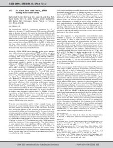
Figure 7. A linear systolic array for sequence comparison.
Here cdel(s,) is thecost ofdeletingsi,c,",(tf) is thecostofinsertingt,, andcEUh(si,tfj is the cost of substituting t, for .s,. With one processor, this dynamic programming formulation requires time proSrc Chr Out Src Chr In ,'4 portional to the product of the lengths of Character the two sequences. Because DNA sequences comparator are long (tens of thousands of characters) ,x4 Tgt Chr In and genetic databases are large (tens of Tgt Chr Out millions of characters), exhaustive searches can require hours of mainframe time. Fortunately, there is tremendous potential for parallelism in the recurrence given above: All values di, can be calculated simultaneously for a given k = U+;). Mapping the recurrence onto a linear systolic array is a straightforward procedure. Src Dst Out Src Dst In One such arrangement is shown in FigFinite state machine ure 7. Thecharacters ofthe source sequence (Mod 4) flow in from the left, while the characters 2 ,--Tgt Dst In Tgt Dst Out of the target flow in from the right. Each processing element evaluates the recurrence every clock "tick." The Princeton Nucleic Acid Comparator (P-NAC) is an NMOS realization of this Figure 8. Block diagram of a sequence comparison processing element. array. designed and built for the sole purpose of comparing DNA sequences.' The implementation assumed that cdel(s,j= cln5(tJ) = I , for all s i and t], and that c5Uh(.s,,rj) = 0 if s, matches t, and ~,,~(.s,,t,) = 2 otherwise. Benchmarks established that P-NAC was parator and a finite state machine (see FigEach systolic processingelement is realseveral hundred times faster than mini- ure 8). The source and target characters, ized using 12 CLBs arranged as a 6 X 2 computers of the day. each four bits, are compared during the first module. In thecurrent implementation, this clock phase. The finite state machine com- basic cell is replicated 24 times on each of Splash implementation. In the Splash putes a new distance based on the results of the 30 middle chips, and 12 timcs on the implementation, a processing element is this comparison and the source and target two end chips, to yield a total of 744 procomposed of two modules: a character com- distances during the second clock phase. cessing elements.
-
4-
e
,
January 199 I
87
Table 1. Benchmark results for 100 comparisons of 100-long sequences. ~~
~
Best time in seconds
Speedup
Splash
0.020
2.700
1 MHz, Sun 3/260 host
P-NAC
0.91
60
Special-purpose NMOS device, Sun 2 host
3.7
14
C compiler, optimization
Machine
Multiflow Trace
Notes
level 5 , 14 functional units Connection Machine CM-2
4.7
11
Cray-2
6.5
8.3
Vector Pascal, one head
Convex C1
8.9
6.0
Vector C compiler, optimization level 2
Sun 31140
48
1.1
C compiler
Sun Sparcstation I
5.8
9.3
C compiler
DEC VAX 111785
54
1 .o
C compiler
Two characters from each sequence are transferred from Splash’s dual-ported memory card to the array’s input FIFO every microsecond at a I-megahertz system clock. These are unpacked by logic in chip 0 and pumped into the appropriate sides of the systolic array. The evolutionary distance is maintained in an up/down counter in chip 3 1 and read from the output FIFO as the last step ofthe comparison. All logic was specified using the LDG language. The time needed to download the configuration file to Splash is negligible if more than a few comparisons are going to be performed. Once the program is in place, the systolic array reinitializes itself asynchronously; two new sequences may be input as soon as the previous ones have exited. Currently the implementation is exercised using Trigger, although eventually it will be callable as a stand-alone C language subroutine.
Performance evaluation. We have programmed the basic sequence comparison algorithm on a representative assortment of sequential and parallel machines. When performing 100 comparisons of sequences that are 100 characters long, Splash is 45 88
C compiler, Paris library 16,000 processors
times faster than its nearest competitor (the special-purpose P-NAC) and almost 200 times faster than the fastest commercial machine (a Multiflow Trace). See Table 1. Splash and P-NAC exploit significantly more of the problem’s inherent parallelism than do the other machines. As the lengths of the sequences increase, the relative performance of the systolic implementations improves until the problem must be partitioned, when the performance of all machines scales quadratically. (For Splash, this partitioning limit is currently 128 x 128 characters, but it can be increased to 256 x 256 characters without much difficulty.) As the number of sequences in the database increases, the relative performance of the Connection Machine improves somewhat (up to a limit of 16K sequences), while the performance of the other machines scales linearly. At present, the speed with which Splash can compare sequences is constrained only by the time it takes to transfer data from the dual-ported RAM; while the on-chip logic can be clocked as fast as 4 megahertz, the FIFOs can be driven only at 1 megahertz. Even so, Splash has an unmatched price/ performance ratio for this important application.
T
he actual design and construction of real hardware formed the impetus for many components, both hardware and software, that would not have been recognized as desirable in a “paper” machine. Fundamental changes, such as adding CLB and IOB templates and shape/ position directives to LDG were driven by unforeseen shortcomings in Xilinx support software. Crucial features such as state readback provided a convenient, efficient, and detailed utility for debugging and production designs to provide the user with necessary data. This feature grew out of need, not out of prior presumptions. Having real users with a multitude of applications brought many desirable features to light, such as the C runtime support library. It also led to significant modifications, for example, changes to LGD syntax that simplified reading and writing code. For the next Splash design, we would like to introduce floating-point processors as originally envisioned. Since global control of the board can be difficult, more lines linking all of the stages would be helpful for many applications. A microprocessor to control the board might also be useful. Finally, an algorithmic language would enhance the designer’s ability to capture the logic and flow of abstract systolic designs.
References I . Annardtone et al., “Warp Architecture and Implementation,“ Proc. 13th Ann. Symp. ConipiiterArcliitecture.June 1986, pp. 346356. 2. P. Lee and Z.M. Kedem, “On High-speed Computing with a Programmable Linear Array,” Proc. Supercomputing 88, Vol. 1.CS Press, Los Alamitos, Calif., Order No. 882,
pp. 425-432.
3. H.T. Kung, “Why Systolic Architectures?” Comnpurer,Vol. 15, No. 1, Jan. 1982, pp. 3746. 4. S. Borkar et al., “iWarp: An Integrated Solution to High Speed Parallel Computing,” Proc. Supercomputing 88, Vol. I , CS Press,
Los Alamitos, Calif., Order No. 882, pp. 330-339.
5. M. Gokhale et al., “Splash: A Reconfigufable Linear Logic Array,” Proc. Znr ’ I Con5 Application-Specific Array Processing, Sept.
1990; also available as Tech. Report SRC TR90-012, Supercomputing Research Center, Bowie, Md. COMPUTER
6.
D.P. Lopresti, “P-NAC: A Systolic Array for Comparing Nucleic Acid Sequences,” Computer, Vol. 20, No. 7, July 1987,pp. 9899.
7. D. Sankoff and J.B. Kruskal, eds., Time Warps, String Edits, and Macromolecules: The Theory and Practice of Sequence Comparison, Addison-Wesley, Reading, Mass.,
1983.
8. P. Bertin et al., “Introduction to Program-
mable Active Memories,” DEC Paris Research Laboratory, Tech. Report 3, 1989.
9. The Programmable Gate Array Data Book, Xilinx, Inc., 1989. 10. M. Gokhale et al., “The Logic Description Generator,” Proc. Int’l Conf ApplicarionSpecific Array Processing, 1990; also available as Tech. Report SRC TR90-011, Supercomputing Research Center, Bowie, Md.
William Holmes has been with the Supercomputing Research Center since 1987 as manager of the Horizon and Splash projects. Before that, he worked for NASAEoddard, providing computer support to spacecraft missions. Holmes received his BS degree in mathematics from LaSalle University in 1966and his MS in mathematics from Georgetown University in 1971.
Ronald Minnich is a systems programmer at the Supercomputing Research Center, working in operating systems research and high-speed networks. His most recent work includes the Mether Network Shared Memory, a caching file system for Unix, and the Trigger symbolic debugger for Splash. Before joining SRC in 1988, Minnich was a graduate student at the University of Delaware. He just completed a PhD in computer science at the University of Pennsylvania. Minnich is a member of Eta Kappa Nu, the IEEE Computer Society, and ACM.
11. D.J. Kopetsky, “Horse: Simulator of the Horizon Supercomputer,” Proc. Supercomputing 88, Vol. 1, CS Press, Los Alamitos, Calif., Order No. 882, pp. 53-54; also available as Tech. Report SRC TR88-013, Supercomputing Research Center, Bowie, Md.
I
Maya Gokhale is a research staff member in systems at the Supercomputing Research Center in Bowie, Maryland, working in languages and compilers for high-performance computers.Prior to joining SRC in 1988, she was an assistant professor at the University of Delaware. She also has seven years of industry experience with Burroughs and Hewlett-Packard as a design engineer. Gokhale received a BS degree in mathematics (magna cum laude) from Wake Forest University in 1972 and MSE and PhD degrees in computer and information sciences from the University of Pennsylvania in 1977 and 1983.
January 1991
Andrew Kopser has been a member of the research staff at the Supercomputing Research Center since 1987 His research interests are in computer architecture and hardware modeling Kopser received his BSEE from the University of Virginia in 1987 He received his MS degree in 1989 from the University of Maryland at College Park, where he is currently pursuing a PhD, also in electrical engineering He is a member of the IEEE Computer Society
Douglas Sweely is a member of the Supercomputing Research Center’s research staff. His interests include embedded special-purpose processors and microfabrication techniques. Before joining SRC in 1988, he designed realtime data acquisition systems for particle detectors at Brookhaven National Laboratory. Sweely received the BS degree in physics from Ursinus College in 1981 and the MS degree in measurement and control from Carnegie Mellon University in 1983.
Sara Lucas is a member of the research staff of the Supercomputing Research Center. Her current interests include computer-aideddesign and programming tools for systolic arrays. She received the BS degree in computer science from San Francisco State University in 1987. She is a member of ACM.
Daniel Lopresti is an assistant professor in the Department of Computer Science at Brown University. He is also a consultant for the Supercomputing Research Center. His research interests include parallel architectures,VLSI design, and computational aspects of molecular biology. Lopresti received the AB degree in mathematics from Dartmouth College in 1982 and the MA and PhD degrees in computer science from Princeton University in 1984 and 1987.
Readers can write to the authors at the Supercomputing Research Center, 17100 Science Dr., Bowie. MD 20715.
89