The International Archives of the Photogrammetry, Remote Sensing and Spatial Information Sciences, Volume XLII-3, 2018 ISPRS TC III Mid-term Symposium “Developments, Technologies and Applications in Remote Sensing”, 7–10 May, Beijing, China
BUILDING FACADE MODELING UNDER LINE FEATURE CONSTRAINT BASED ON CLOSE-RANGE IMAGES Y. Liang 1, Y. H. Sheng 2 1
Dep. of Naval Architecture & Ocean Engineering, JiangSu Maritime Institute, China -
[email protected] 2 Dept. of Geography, Nanjing Normal University, China-
[email protected]
Commission III Urban Sensing and Mobility
KEY WORDS: Close-range Image, Line Feature, Building, Modeling
ABSTRACT: To solve existing problems in modeling facade of building merely with point feature based on close-range images , a new method for modeling building facade under line feature constraint is proposed in this paper. Firstly, Camera parameters and sparse spatial point clouds data were restored using the SFM , and 3D dense point clouds were generated with MVS; Secondly, the line features were detected based on the gradient direction , those detected line features were fit considering directions and lengths , then line features were matched under multiple types of constraints and extracted from multi-image sequence. At last, final facade mesh of a building was triangulated with point cloud and line features. The experiment shows that this method can effectively reconstruct the geometric facade of buildings using the advantages of combining point and line features of the close - range image sequence,especially in restoring the contour information of the facade of buildings.
1. INTRODUCTION 1.1 General Instructions With the rapid development of computer information technology, digital city has played an irreplaceable role in the urban construction. Building, however, constitute the most important component of the digital city . How to acquire the building façade information and with low cost and high precision has become an important research topic(Pang,2015). There are three main current methods of extracting information as follows, one way is to reconstruct the geometric modeling of building using CAD ,with the help of the two-dimensional GIS plane data and other auxiliary data, which are generated by total station survey or aerial photogrammetry, the other way is to obtain the three-dimensional point cloud information of the building facade directly using a three-dimensional laser scanner, another way is to extract the facade geometric information of the building using a sequence of close-range images from different perspectives of the building[2]. The close-range images can reflect the geometric details of the building surface and have realistic texture information, and it can provide an effective way to quickly, accurately and realistically reproduce the three dimensional city information, which has been a hot topic in the field of photogrammetry and computer vision. The extraction of geometric feature (point feature and contour feature) of building facade is the important step, and it also determines the accuracy of 3D reconstruction of buildings. In image information, point feature localization is accurate, by which the mapping relationship between two-dimensional image and 3D geometry can be restore effectively. As the basic element for realizing 3D reconstruction, points can form lines and planes. The concave and convex boundaries of doors and windows and walls are the main features of the building, which control the structure of the whole building. Because the point cloud data extracted from the image sequence is disordered and
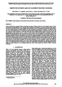
unevenly distributed, there are still some unsolved problems in extracting the geometric contour features of the building facade simply from the point cloud data. In this paper a new method of reconstructing building façade is provided that integrates point features and linear features(Figure 1), and how to extract the feature and line feature of the building facade is the key to the method.
Extraction of point feature
Extraction of linear feature
buildings
3D Modeling of building facade
Linear feature fitting
Line feature matching
3D calculation of linear feature
Fig.1 The Process of Building Facade Modeling 2. EXTRACTION OF SPATIAL POINT FEATURES In the process of extraction of spatial point features, the calculation of camera parameters is important, because it can directly establish the mapping relationship between 3D geometric coordinates and 2D image coordinates, the camera parameters are implied in the camera imaging model that describe the imaging geometry relationship of the target object in the image and the world coordinate. As shown in formula 1, the projection matrix P is a 3 ×4 matrix, K represents the
This contribution has been peer-reviewed. https://doi.org/10.5194/isprs-archives-XLII-3-993-2018 | © Authors 2018. CC BY 4.0 License.
993
The International Archives of the Photogrammetry, Remote Sensing and Spatial Information Sciences, Volume XLII-3, 2018 ISPRS TC III Mid-term Symposium “Developments, Technologies and Applications in Remote Sensing”, 7–10 May, Beijing, China
internal parameters of the camera. [R, t ] represents the external parameter of the camera, including the rotation matrix and the translation vector. u0 f γ u 1/dx Zc v = 0 1 / dy v0 0 1 0 0 1 0 fu =0 0
s fv 0
0 f 0
0 0 R 0 0 T 0 1 0
X w t Yw 1 Z w 1
X w u0 Y v0 [R t ] w = K [R t ]X = PX Zw 1 1
Fig.3 Line Fitting
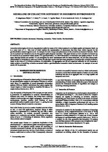
(1) In this paper, aided by the existing technology of structure from motion (SFM) in computer vision, the solutions of camera parameters and three-dimensional sparse spatial points are calculated simultaneously based on beam adjustment optimization(Snavely,2006; Pollefeys,2001). In order to get better surface reconstruction result, it is far from enough to rely solely on the 3D spatial point features, it is necessary to encrypt the dense point cloud information on the basis of the sparse points. In this paper, multi-view stereo (MVS) technology is used that diffuses the seed point to the surrounding area to get dense spatial point clouds or patches, and recover of dense point clouds (Yasutaka,2008). On this basis, this paper focuses on the extraction of the spatial line features. 3. EXTRACTION OF SPATIAL LINEAR FEATURES 3.1 Detection of Linear Feature Considering Direction and Length Before extracting the straight line feature, First of all, it is necessary to detect the straight line features initially, and then fit as complete as possible. In this paper, LSD algorithm is used in detecting edge based on gradient direction information(Gromopone,2010), this method firstly use Gauss filter to reduce the effect of noise, then calculate each pixel’s gradient magnitude and direction of, sort the gradient magnitude, classify pixels with similar gradient direction and approximate into a rectangular area, the centre line of rectangular is edge detected, as shown in figure 2.
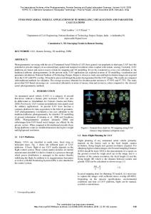
Due to the influence of the direction and relative length of the line segment on the fitting result, this paper considers the property of line segment, and use them as weight parameter to fit the line features . To determine the fitted line segment, it is necessary to calculate the direction and position. As shown in figure 3, i and j are two line segments needed to be fitted, li , l j and θ i , θj , respectively represent the length and direction of line segments, a and b are two ends of line segments, c and d are two ends of line segments. The point G on the fitted straight line can be calculated using length as weight, as shown in formula 2. In other words, the fitted line must pass through the point, xG = yG =
l i ( a x + b x ) + l j (c x + d x ) 2(l i + l j ) l i ( a y + b y ) + l j (c y + d y ) 2(l i + l j )
(2)
The direction of the line is defined as follows in formula3. liθ i + l jθ j li + l j θ j θr = liθ i + l j θ j − π θ j li + l j
θi − θ j ≤
θi − θ j >
π 2
(3)
π 2
The line segment after the fitting passes through the point G and the direction is θ r . Next, project point a,b,c,d to fitted line, and the projection point with the maximum range is taken as the end point of the fitted line segment. 3.2 Match of Linear Features under Multiple Constraints
Fig.2 The Process of LSD Because the LSD algorithm partly filters image noise, it cannot avoid fracture and overlap of the linear segment caused by noise at the edge. To get as complete as possible straight line features, it is necessary to further fit the line segment.
The close range image has the characteristics of large distortion and close-range shooting, in addition, building targets tend to have less local textures and are vulnerable to the occlusion of other objects, such as trees, vehicles, pedestrians , all these factors led to a problem that the detected line segments tend to be too long or too short, in other words, the endpoints of a couple of homonymous line is not guaranteed to be matched, resulting in the properties(the length and the gray level of the neighbourhood ) of a couple of homonymous line are inconsistent. Without effective geometric constraints, it is difficult to match the line features. In this paper, a method of line feature matching under multiple constraints is proposed(Liang,2014), this method can effectively realize the matching of line features under rotation, scale, illumination and affine transformation. The steps are as follows: (1) On the basis of the realization of feature point matching and linear feature detection, on both sides of the line feature, the
This contribution has been peer-reviewed. https://doi.org/10.5194/isprs-archives-XLII-3-993-2018 | © Authors 2018. CC BY 4.0 License.
994
The International Archives of the Photogrammetry, Remote Sensing and Spatial Information Sciences, Volume XLII-3, 2018 ISPRS TC III Mid-term Symposium “Developments, Technologies and Applications in Remote Sensing”, 7–10 May, Beijing, China
point features with the nearest vertical distance to the line features are firstly found out, two nearest point features located at different sides can been connected to form a virtual line, according to the affine invariance principle of intersecting lines, the line feature and the virtual line must be crossed. Based on this principle, the candidate line features in another image can be easy to found out, and the search scope is reduced evidently. as shown in Figure 4, u,v and u’,v’ as a pair of matching points, m,n and m’,n’ as separately extracted line segments l1 and l2.
The matrix describes the gray level information near line L. Due to the different scale of the image, the length of the homonymous lines in different images is also different. In order to get the a straight line description that is independent of direction and length, each row’s mean value of is taken as the gray level description of line L, that is, the column vector with rows. can be represented as follow:
(6) ,i=1,2,
Where gi=
Fig.4 The Affine Invariance of Intersecting Line (2) Then the overlapping parts of the homonymous line are determined by the constraint of polar lines between multiple views, unifying the attribute consistency of the homonymous line features(Fu,2008). (3) Finally the line features are matched with the angle similarity of the straight line and the virtual line (formula 4), the gray’s similarity of the support domain (formula 5). The angle similarity measure is as follows:
,2r+1。
In order to highlight the importance of pixel gray level near the straight line, the mean value of each sub region is assigned as a distance weight, and the larger the weight is, the smaller the distance is, so the gray level description of line L with weights is as fllows:
(7)
if i=1,2,…,r+1,then k=i, and if i=r+2,
Where ,
r+3,…,2r+1, then k=2(r+1)-i.
(4) Where
is the angle between the straight line and the virtual
line in the left image, is the angle between the candidate line and the corresponding virtual line in the right image.
Finally, the correlation coefficient of the gray mean of the linear segment with weight is taken as the gray similarity measure, as is shown in formula 8.
The line support domain is shown in figure 5.
(8)
Among them,
,,
represent respectively the i gray mean
vector with weight of line L and R.
and
represent
respectively the mean value of the gray mean vector with weight. Fig.5 Straight Line Support Domain Description
3.3 Recovery of Spatial Line Features
Assuming that the support area of straight line feature L is a matrix of size, the gray value of the point j on the parallel line segment i is represented as
, this matrix can be
represented as follow:
On the basis of the projection matrix (3×4) is calculated that contacts the image points and the three-dimensional points, the projection matrix (Cordelia ,2000;Hartley ,2009; Yu,2009;) of the spatial line is as follows: (9)
(5)
This contribution has been peer-reviewed. https://doi.org/10.5194/isprs-archives-XLII-3-993-2018 | © Authors 2018. CC BY 4.0 License.
995
The International Archives of the Photogrammetry, Remote Sensing and Spatial Information Sciences, Volume XLII-3, 2018 ISPRS TC III Mid-term Symposium “Developments, Technologies and Applications in Remote Sensing”, 7–10 May, Beijing, China
and
represent respectively the first 3 columns and fourth
columns of the projection matrix, matrix.
is an antisymmetric
The relationship between the line on the image plane and the spatial line is as follows: l=QL
(10)
The space position of a straight line can be calculated by the upper formula, as shown in figure 6.
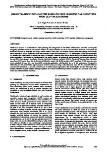
(a)Spatial Point Features of Building1
Fig.6 3D Reconstruction of Space Straight Line 4. RECONSTRUCTION OF SURFACE MESH The traditional surface reconstruction algorithm cannot effectively identify the distinct feature area, thus limiting the application scope of the surface reconstruction method. According to the method proposed in the literature(Wang,2008), on the basis of the surface growth algorithm, the surface reconstruction process involves visibility and vertex selection and normal consistency , such steps are consistent to guide the use of line feature. The correct reconstruction of the boundary part is realized with the help of the characteristic line, in adhering to the simple and effective advantage of surface growth algorithm. 5. EXPERIMENT
(b)Spatial Line Features of Building1
(c) 3D Facades Model Fig. 8 3D Geometry Data of Building 1
According to the methods discussed in this paper, the reconstruction of three-dimensional geometric façade of building is conducted, the two groups original images(Figure 7), of extracted geometric features of 3D points and lines and the reconstructed facade of the two building are shown in Figure 8 and Figure 9 respectively.
(a)Spatial Point Features of Building2
(a)Images of Building 1
(b)Spatial Line Features of Building2 (b)Images of Building2 Fig.7 Test Data
This contribution has been peer-reviewed. https://doi.org/10.5194/isprs-archives-XLII-3-993-2018 | © Authors 2018. CC BY 4.0 License.
996
The International Archives of the Photogrammetry, Remote Sensing and Spatial Information Sciences, Volume XLII-3, 2018 ISPRS TC III Mid-term Symposium “Developments, Technologies and Applications in Remote Sensing”, 7–10 May, Beijing, China
(c) 3D Facades Model Fig. 9 3D Geometry Data of Building 2 As shown in figure 8(a) and figure 9(a),the extraction results of 3D point features from the image sequence are unordered and unevenly distributed, so it is almost impossible to reconstruct building façade relying solely on point cloud data. As shown in figure 8(b) and figure 9 (b), the extracted three dimensional linear features are mostly complete, this proves that it is not easy for linear feature reconstruction to be affected by obscuring. Although a part of the line is not visible, the rest can still provide enough information for 3D reconstruction. The reconstructed result shows the contour profile of buildings and the parallel and vertical relations among 3D line features, which further confirms the advantages of the line feature in describing the boundary structure and topological relationship of the scene. From figure 8(c) and figure 9(c), it can be confirmed that the method based on this paper can effectively reconstruct the 3D building façade , and the 3D line features play a good role in restraining the geometric model. 6. CONCLUSION In this paper, the object of modeling building facade is realized under line feature constraint based on close-range images. Aided by the technology of SFM, the camera parameters and the spatial point cloud data are restored, and the relationship is established between a two-dimensional image and 3D geometric space, then the characteristic straight line is detected based on image gradient , fitted considering the direction and length, and matched under multi constraint, 3D façade reconstruction of building is further realized based on point and line features. It is worth noting that the holes in the result of reconstructed model need to be repaired with specific algorithms or interactive methods, in addition, because of the noise, there are still more or less distortions in the local area of 3D surface model, this is also a part of the further work that needs to be focused on.
Fu D.,Wang C.,Xu Y.D.,et al,2008. A new algorism of matching line segments. Journal of National University of Defense Technology, 30(1),pp.115-119. Gromopone vGR., Jakubowicz J., Morel J. M., et al,2010.LSD: A fast line segment detector with a false detection control. IEEE Transactions on Pattern Analysis and Machine Intelligence , 32(4) ,pp.722-732. Hartley R., Zisserman A.,2000. Multiple view Geometry in Computer Vision. Cambridge University Press , pp. 321-332. Liang Y., Sheng Y.H., Zhang K., et al,2014.The method of linear feature matching based on local affine invariant and epipolar constraint for close-range images. Geomatics and Information Science of Wuhan University, 39(2) ,pp. 229-233 Pang S.Y., Liu Y.W, Zuo Z.Q, et al, 2015.Combination of region growing and TIN edge segmentation for extraction of geometric features on building facades. Geomatics and Information Science of Wuhan University, 40(1), pp.102-105. Pollefeys M., Vergauwen M., Cornelis K., et al, 2001.3D acquisition of archaeological heritage from images. Workshop Pre-& Proto Morphology, pp. 73-78. Snavely N, Seitz S.M., Szeliski R, 2006. Photo tourism: exploring photo collections in 3D. ACM transactions on graphics (TOG), 25(3), pp. 835-846. Wang Y.B.,2008. Research on Surface Reconstruction of Spatial Objects from Point Cloud and Its Multi-Resolution Represention. Nanjing Normal Univesity. Yu Q.F., Sheng Y.,2009. Videometrics: Principles and Researches. Beijing:Science Press ,pp.15-18. Yasutaka F, Jean P, 2008.Accurate, Dense, and Robust Multiview Stereopsis. IEEE Transactions and Pattern Analysis and Machine intelligence,pp.1-14.
Revised March 2018
ACKNOWLEDGEMENTS This work was supported by the research project of Jiangsu provincial bureau of surveying geoinformation (JSCHKY201605).We also wish to acknowledge the expert group for the advice and guidance on this work. REFERENCES Cordelia S., Zisserman A., 2000.The geometry and matching of lines and curves over multiple views. Int. J. Computer Vision, 40(3) ,pp.199-233. Debevec P. E., Taylor C. J., Malik J,1996. Modeling and rendering architecture from photographs: A hybrid geometryand image-based approach. In: Proceedings of the 23rd Annual Conference on Computer graphics and interactive techniques, pp.11-20.
This contribution has been peer-reviewed. https://doi.org/10.5194/isprs-archives-XLII-3-993-2018 | © Authors 2018. CC BY 4.0 License.
997