IP: 114.70.10.206 On: Fri, 06 Sep 2013 05:21:48. Copyright: ..... C. Martin, O. Crosnier, R. Retoux, D. Bélanger, D. M. Schleich, and. T. Brousse, Adv. Funct. Mater ...
Copyright © 2013 American Scientific Publishers All rights reserved Printed in the United States of America
Journal of Nanoscience and Nanotechnology Vol. 13, 7855–7859, 2013
In Situ Synthesis and Cell Performance of a Si/C Core–Shell/Ball-Milled Graphite Composite for Lithium Ion Batteries Dong-Won Jung1 , Kwang-Hyun Kim1 , JungKyoo Lee2 , Byung-Seon Kong3 , and Eun-Suok Oh1� ∗ 1
RESEARCH ARTICLE
School of Chemical Engineering, University of Ulsan, Ulsan 680-749, Korea Department of Chemical Engineering, Dong-A University, 840 Hadan 2-Dong, Sahaku, Busan 604-714, Korea 3 KCC Central Research Institute, 83 Mabook-Dong, Yongin, Kyunggi-Do 446-912, Korea 2
A high-capacity silicon-carbon core–shell (Si/C) supported by ball-milled graphite (BMG) was synthesized in situ using a hydrosilylation reaction and tested as an anode material for lithium ion batteries (LIBs) in the investigation of the effects of dual buffer layers of carbon shell and BMG. The Si/C/BMG sample effectively absorbed high volumetric expansion/contraction generated during charge/discharge process due to the assistance of dual elastic buffers of carbon shell and BMG. As a result, after 50 charge/discharge cycles, the Si/C/BMG electrodes still had a very high capacity of 1615 mAh/g, whereas raw Si, Si/C, and a mechanical mixture of Si/C and BMG were less by than 500 mAh/g. The results various electrochemical techniques Delivered Publishing Technology to: of Ulsan National Institute ofcharacterization Science and Technology revealed that the dual buffer layers were favorable in decreasing electron and ion transfer resistance. IP: 114.70.10.206 On: Fri, 06 Sep 2013 05:21:48 It was also shown from exCopyright: situ TEM results that the carbon Publishers layers behaved as anti-amorphization American Scientific layers decreasing the amorphization rate of crystalline Si during the alloying/dealloying of Li with Si.
Keywords: Si, Si/C Composite, Ball-Milled Graphite, Anode Material, Lithium Ion Battery.
1. INTRODUCTION Graphite is an anode active material with a theoretical reversible capacity of 372 mAh/g and which is generally used in commercial lithium-ion batteries (LIBs) due to its stable lithium intercalation/deintercalation in a wellcrystallized structure. Recently, due to the requirements of electric vehicle power sources, a need has arisen for highperformance LIBs with high energy density and power. Silicon (Si) has been extensively studied as an anode active material as the theoretical capacity of Si is as high as 4200 mAh/g. However, Si experiences a large volume change, up to 310%, during insertion/desertion of lithium ions into the Si lattice.1 The most significant problem related to this phenomenon is mechanical stress build-up in the electrodes, leading to the structural collapse of the Si crystal and, ultimately, rapid capacity fading. To resolve these problems, several methods have been introduced, ∗
Author to whom correspondence should be addressed.
J. Nanosci. Nanotechnol. 2013, Vol. 13, No. 12
including the use of nanosized Si particles2–5 and core– shell composites of Si and inactive materials.6–9 Carbon shells have been commonly used as a buffer material to enhance LIB performance due to their porous structure and high electrical conductivity.10–12 The pores in porous carbon provide extra space for the volume expansion of lithiated Si. Another possible method to mitigate expansion is to disperse nanosized-Si particles in the carbon buffer matrix in order to absorb the significant volume change and to ultimately improve the electrochemical stability during cycling.13 In this study, we use Si nanoparticles, which are byproducts of the manufacturing process of polycrystalline Si for solar cells, as a high-capacity anode material. We also adopted an in situ synthesized Si/carbon core– shell (Si/C) supported by ball-milled graphite (BMG) as a buffer matrix to prevent capacity fading of the Si/C composite.14 The dual elastic buffers of a carbon shell and BMG can effectively control the volume expansion of Si nanoparticles.
1533-4880/2013/13/7855/005
doi:10.1166/jnn.2013.8129
7855
In Situ Synthesis and Cell Performance of a Si/C Core–Shell/Ball-Milled Graphite Composite for Lithium Ion Batteries
Jung et al.
2. EXPERIMENTAL DETAILS
RESEARCH ARTICLE
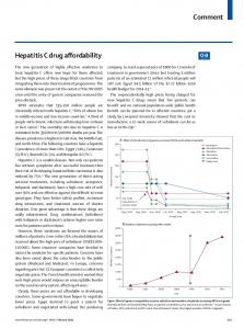
2.1. Synthesis of the Si/C/BMG Composite A Si/C/BMG composite was synthesized by a hydrosilylation reaction using resorcinol and formaldehyde.5� 15 Nanosized-Si powder was (KCC Co., Korea) obtained from the manufacturing process of solar-grade polycrystalline Si, and 0.2 g was sonicated in a vial filled with 7.6 ml deionized water for 1 h, and 0.386 g of resorcinol, 0.0148 g of 0.05 N sodium carbonate, and 0.232 g of formaldehyde were sequentially added to the Si suspension. Next, 4.7 g of commercial natural graphite (Sodiff Co., Korea) was ball-milled with 13 g of ethylene glycol at 200 rpm for 24 hrs and added to the suspension. Upon formation of a gel by heating the suspension in a Si oil bath at 80 � C for 1 hr, the gel was transferred to a convection oven at 80 � C and was aged for 16 hrs. The resultant solid was filtered and cleaned with water and ethanol and dried in a vacuum oven at 60 � C. The dried composite was carbonized in a horizontal tube furnace at 800 � C under nitrogen atmosphere for 1 hr. During carbonization, the nanosized-Si particles are covered with a carbon shell and the reduction of resorcinol connects BMG and the Si/C core–shell. A schematic illustration for these synthesis procedures is shown in Figure 1.
Delivered by Publishing Technology to: Ulsan National Institute of Science and Technology 2.2. Physical and Electrochemical IP: Characteristics 114.70.10.206 On: Fri, 06 Sep 2013 05:21:48 of a Si/C/BMG Composite Copyright: American Scientific Publishers X-ray diffraction (XRD) analysis (Rigaku, RAD-3C) using a CuK� (� = 1�541 Å) source was performed in order to identify the crystal structure of Si/C on BMG. The weight percentages of Si in the composites were measured using a thermogravimetry analyzer (TGA, TA Ins., Q50). Raman spectra were collected using a Renishaw Raman spectrometer with a 632.8 nm laser. The morphologies of pristine Si, Si–C and Si–C/BMG composites were characterized using a transmission electron microscope (TEM, Jeol, Jem-2010). The anodic characteristics of the synthesized composites were evaluated using CR2016 coin cells with Lifoil as a counter electrode. The working electrodes were composed of 60 wt% composite, 20 wt% vapor growth carbon fiber, and 20 wt% polyvinyl alcohol16 as a binder. The mass loadings of the electrodes were in the range of 1�39 ± �04 g/cm3 . 1M LiPF6 (Panaxetec Co., Korea) dissolved in a 1:1:1 (v/v/v) mixture of ethylene-carbonate, dimethyl-carbonate, and ethylmethyl-carbonate was used as an electrolyte. The cells were galvanostatically discharged to 0.005 V and charged to 1.0 V at a current density of 50 mA/g for the first two cycles and 300 mA/g for the next 48 cycles in a battery test system (WBCS3000, WonAtech, Korea). Additionally, electrochemical impedance spectroscopy (VSP, Biologic SAS) was tested over a frequency range of 0.01 Hz to 100 kHz. 7856
Fig. 1. Schematic illustration of synthesis process of Si/C and Si/C/BMG composites.
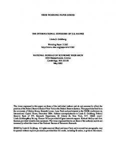
3. RESULTS AND DISCUSSION The crystal structures of the samples were investigated using XRD analysis, and the results are shown in Figure 2. As shown by the XRD peaks of BMG, ball-milling forms graphite with a high crystalline flake texture due to its lamellar structure. XRD peaks observed at 2� = 26� and 54� in graphite correspond to the (002) and (004) crystalline planes of graphite (JCPDS card no. 75-1621), whereas XRD peaks at 2� = 28� , 47� and 56� in Si are related to the (111), (220), and (311) crystalline planes of Si crystal (JCPDS card no. 80-0018) with a face-centered cubic structure. The peak observed at 2� = 43� in the Si/C/BMG indicates the formation of the (110) crystal plane of rhombohedral graphite (JCPDS card no. 75-2078). Figure 3 shows TEM images of the raw Si, Si/C and Si/C/BMG samples. As shown in Figure 3(a), the crystalline structure of Si was confirmed, and its size was approximately 20 nm. As shown in Figure 3(b), carbonlayer-wrapped nanosized-Si particles with a thickness of 5 nm were observed. These Si/C particles were supported on thin graphite exfoliated by ball-milling (Fig. 3(c)). The electron diffraction pattern of a poly-Si grain in the J. Nanosci. Nanotechnol. 13, 7855–7859, 2013
Jung et al.
In Situ Synthesis and Cell Performance of a Si/C Core–Shell/Ball-Milled Graphite Composite for Lithium Ion Batteries
Fig. 4. Raman spectra of (a) ball-milled graphite, (b) raw Si, (c) Si/C core shell, and (d) Si/C/BMG composite.
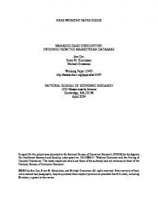
Si/C/BMG is shown in Figure 3(d) and indicates the (111) crystal plane of Si particles, which is consistent with the were nearly the same as determined by TGA analysis: XRD results shown in Figure 2. 76.2 wt% for the Si/C and 78.3 wt% for the Si/C/BMG The Raman spectroscopy result illustrated in Figure 4 (data not shown). Thus, the amount of Si does not affect the shows crystalline differences among the samples. The ratio, as shown in Figure 4. On the other hand, the intensity D-band at 1340 cm−1 and the G-band at 1570 cm−1 in ratios of the G-band over the D-band in Figures 4(c) and Figure 4(a) were assigned to defects and graphitic struc(d) were similar in both the Si/C and Si/C/BMG compostures in BMG, respectively.17 The peak at 2700 cm−1 ites, indicating that the high temperature pyrolysis of BMG was assigned to the second order of the D-band. In the formed non-graphitic structures such as defects. case of raw Si, displayed in Figure 4(b), a strong peak The anodic properties of Si/C/BMG were evaluated via Delivered by Publishing Technology Ulsan National Science andclearly Technology was attributed to crystalline Si. Noto:peaks at 511 cm−1 EIS and Institute coin-halfofcell tests. To see the effects of 114.70.10.206 On: Fri, 06 Sep 2013 05:21:48 corresponding to amorphous-like IP: components with disorBMG and carbon shell support, the cyclic performance of Copyright: American Scientific Publishers dered structures were observed near 480 cm−1 .18 Both Si/C the Si/C/BMG was compared to those of Si, Si/C, and and Si/C/BMG composites displayed peaks attributed to Si/C-mBMG, as shown in Figure 5(a). Si/C-mBMG refers the D- and G-bands of graphite and crystalline Si, even to the mechanical mixture of Si/C and BMG with the same though the peaks were slightly shifted. However, the ratio composition as Si/C/BMG. The initial discharge capacities of their intensities was significantly changed. The ratio of of the Si/C and Si/C-mBMG samples were 1692 mAh/g the intensities of carbon corresponding to both the D- and and 1550 mAh/g, respectively, which were greater than G-bands to the intensity of Si were greater in the Si-C/ Si/C/BMG (401 mAh/g) and less than Si (2532 mAh/g). BMG than in the Si/C sample, potentially due to the high Nanosized-Si particles provide some advantages in terms crystallinity of BMG compared to the carbon shell in the Si/C of high theoretical capacity (4200 mAh/g), high consample. The weight percentages of Si in both composites tact area between the Si particles and electrolyte, and high charge/discharge current rate capability due to the short path lengths for electron and ion transport. However, Si particles experience a huge volumetric change during charging/discharging, which results in a significant loss of capacity attributed to stress build-up in the electrode during use. This is the main reason for the rapid decrease in the discharge capacity of the raw Si electrode, as shown in Figure 5(a). In contrast, wrapping Si with a carbon shell could alleviate the capacity decay rate of the Si/C and Si/C-mBMG electrodes. However, the Si/C/BMG sample still showed a high discharge capacity of 1615 mAh/g after 50 cycles, even though its initial discharge capacity was very low. In the first discharge cycle, both the carbon shell and BMG may interrupt lithium ion insertion into the high capacity Si, Fig. 3. TEM images of (a) Si, (b) Si/C, (c) Si/C/BMG, and (d) Sibut as the charge/discharge repeats, the lithium ion mobilcarbon core shell in the Si/C/BMG sample. The inset in (d) is the electron diffraction pattern of the Si (111) crystal plane. ity increases. This increase in mobility occurs for several J. Nanosci. Nanotechnol. 13, 7855–7859, 2013
7857
RESEARCH ARTICLE
Fig. 2. X-ray diffraction patterns of Si, Si/C, Si/C/BMG, and ballmilled graphite (BMG) samples.
Jung et al.
RESEARCH ARTICLE
In Situ Synthesis and Cell Performance of a Si/C Core–Shell/Ball-Milled Graphite Composite for Lithium Ion Batteries
Delivered by Publishing Technology to: Ulsan National Institute of Science and Technology IP: 114.70.10.206 On: Fri, 06 Sep 2013 05:21:48 Copyright: American Scientific Publishers Fig. 5. (a) Discharge capacities verses cyclic numbers for the electrodes composed of Si, Si/C, Si/C/BMG, and the mechanical mixture of the Si/C and BMG. (b) Nyquist plots of the electrodes after 50 cycles.
reasons, including electrolyte wetting enhancement, and thus the discharge capacity gradually increases over the first few cycles. Additional charge/discharge cycles result in irreversible reactions with Si particles with continuously decrease the reversible capacity. However, capacity fading in Si/C/BMG is reduced compared to Si/C and Si/CmBMG due to the dual elastic buffers of the carbon shell and BMG in the in situ synthesized Si/C/BMG. This cyclic performance can be further improved if the electrolyte is appropriately tuned. To examine the resistances of the electrodes, the electrochemical impedances of 50-cycled electrodes were measured and the results are shown in Figure 5(b). The very high frequency of the x-intercept indicates the solution resistance (RS ), and the size of the semi-circle at the middle frequency region denotes the charge transfer resistance (RCT ). The RCT and RS of the Si/C/BMG sample are smaller than those of the other samples. The carbon shell and BMG dual elastic buffers in the Si/C/BMG effectively absorb the high volumetric expansion/contraction and ensures contact of the active materials. This might prevent the electrode from increasing the resistance for 7858
Fig. 6. Ex situ TEM images of (a) Si, (b) Si/C, and (c) Si/C/BMG samples after 50 charge/discharge cycles. The insets in (b) and (c) are the electron diffraction patterns of the Si.
both lithium ion and electron transfers resulting in the relatively low Si/C/BMG impedance compared to other samples. This low impedance contributes to better cyclic performance, as shown in Figure 5(a). Figure 6 displays ex situ TEM images of the Si, Si/C, and Si/C/BMG after 50 cycles. Crystalline Si was transformed into amorphous Si after the first charge/discharge cycle.19–21 As expected, the Si particles shown in Figure 6(a) show only amorphous phases with the loss of the original crystalline Si. The Si in the Si/C sample also becomes amorphous after repeated charge/discharge cycles, as shown in Figure 5(b). This phase transformation is generated by severe volume expansion/contraction during alloying/dealloying of lithium ions with Si. Alternatively, the electron diffraction patterns in the inset of Figure 6(c) show that some of Si in the Si/C/BMG sample remains J. Nanosci. Nanotechnol. 13, 7855–7859, 2013
Jung et al.
In Situ Synthesis and Cell Performance of a Si/C Core–Shell/Ball-Milled Graphite Composite for Lithium Ion Batteries
in the crystalline phase even after 50 cycles. The dual elastic buffers of the carbon shell and BMG therefore act as anti-amorphization layers that reduce the amorphization rate of crystalline Si during alloying/ dealloying of Li with Si. This may also contribute to the enhancement of the cyclic performance of Si/C/BMG.
Received: 23 April 2012. Accepted: 20 December 2012.
J. Nanosci. Nanotechnol. 13, 7855–7859, 2013
7859
RESEARCH ARTICLE
3. W. Wang and P. N. Kumta, ACS Nano 4, 2233 (2010). 4. A. Magasinski, P. Dixon, B. Hertzberg, A. Kvit, J. Ayala, and G. Yushin, Nature Mater. 9, 353 (2010). 5. C. Martin, O. Crosnier, R. Retoux, D. Bélanger, D. M. Schleich, and T. Brousse, Adv. Funct. Mater. 21, 3524 (2011). 6. L. Guo, H. Lee, D. Kim, and W. Yoon, J. Nanosci. Nanotechnol. 12, 1624 (2012). 7. Y. H. Xu, G. P. Yin, Y. L. Ma, P. J. Zuo, and X. Q. Cheng, J. Mater. Chem. 20, 3216 (2010). 4. CONCLUSIONS 8. H. Kim and J. Cho, Nano. Lett. 8, 3688 (2008). 9. N. Coppey, L. Noé, M. Monthioux, and B. Caussat, J. Nanosci. A Si/C/BMG composite was successfully synthesized Nanotechnol. 11, 8392 (2011). in situ by hydrosilyation using resorcinol and formalde10. L.-F. Cui, R. Ruffo, C. K. Chan, H. Peng, and Y. Cui, Nano. Lett. hyde. Dual buffer layers composed of a carbon shell 9, 491 (2009). and BMG matrix significantly enhanced the cyclic per11. P. Gao, J. Fu, J. Yang, R. Lv, J. Wang, Y. Nuli, and X. Tang, Phys. formance of high capacity, nanosized-Si by effectively Chem. Chem. Phys. 11, 11101 (2009). absorbing the volumetric expansion generated during the 12. S.-H. Ng, J. Wang, D. Wexler, K. Konstantinov, Z.-P. Guo, and H.-K. charge/discharge processes. This contributes to a relative Liu, Angew. Chem. Int. Ed. 45, 6896 (2006). 13. J. K. Lee, M. C. Kung, L. Trahey, M. N. Missaghi, and H. H. Kung, decrease in the resistances of ion and electron transfers, Chem. Mater. 21, 6 (2009). as well as a decrease in the rate of amorphization of crys14. D. W. Jung, J. H. Jeong, B. S. Kong, J. K. Lee, and E. S. Oh, talline Si compared to raw Si and Si/C samples. J. Nanosci. Nanotechnol. 12, 3317 (2012). 15. Y. S. Jung, K. T. Lee, and S. M. Oh, Electrochem. Acta 52, 7061 Acknowledgments: This research was supported by the (2007). Basic Science Research Program through the National 16. H. K. Park, B. S. Kong, and E. S. Oh, Electrochem. Commun. Research Foundation of Korea (NRF) funded by the 13, 1051 (2011). Ministry of Education, Science and Technology (201017. D. W. Jung, J. H. Jeong, K. H. Kim, B. S. Kong, and E. S. Oh, 0024077). J. Nanosci. Nanotechnol. 12, 5435 (2012). 18. H. Li, X. Huang, L. Chen, G. Zhou, Z. Zhang, D. Yu, Y. J. Mo, and N. Pei, Solid State Ionics 135, 181 (2000). References and Notes 19. H. Kim, B. Han,ofJ.Science Choo, andand J. Cho, Angew. Chem. Int. Ed. Delivered by Publishing Technology to: Ulsan National Institute Technology 10151 (2008). 1. L. F. Cui, Y. Yang, C. M. Hsu, andIP: Y. 114.70.10.206 Cui, Nano Lett. 9, On: 3370 Fri, 06 47, Sep 2013 05:21:48 20. Y. M. Publishers Kang, S. M. Lee, S. J. Kim, G. J. Jeong, M. S. Sung, W. U. (2009). Copyright: American Scientific Choi, and S. S. Kim, Electrochem. Commun. 9, 959 (2007). 2. H. Kim, M. Seo, M. H. Park, and J. Cho, Angew. Chem. Int. Ed. 49, 2146 (2010). 21. J. Li and J. R. Dahn, J. Electrochem. Soc. 154, A156 (2007).