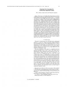
C is for Circuits: Capturing FPGA Circuits as Sequential Code for Portability Scott Sirowy*, Greg Stitt†, Frank Vahid*‡ *Dept. of Computer Science and Engineering University of California, Riverside
{ssirowy,vahid}@cs.ucr.edu ‡
†
Dept. of Electrical and Computer Engineering University of Florida
[email protected]
Also with the Center for Embedded Computer Systems, University of California, Irvine
Abstract Synthesizing common sequential algorithms, captured in a language like C, to FPGA circuits is now well-known to provide dramatic speedups for numerous applications, and to provide tremendous portability and adaptability advantages over circuit implementations of an application. However, many applications targeted to FPGAs are still designed and distributed at the circuit level, due in part to tremendous human ingenuity being exercised at that level to achieve exceptional performance and efficiency. A question then arises as to whether applications for FPGAs will have to be distributed as circuits to achieve desired performance and efficiency, or if instead a more portable language like C might be used. Given a set of common synthesis transformations, we studied the extent to which circuits published in FCCM in the past 6 years could be captured as sequential code and then synthesized back to the published circuit. The study showed that a surprising 82% of the 35 circuits chosen for the study could be rederived from some form of standard C code, suggesting that standard C code, without extensions, may be an effective means for distributing FPGA applications. Categories and Subject Descriptors D.1.4 [Software]: – Programming, Sequential programming B.5.2 [Hardware]: – RTL, Automatic Synthesis General Terms Algorithms, Design, Languages, Performance
1. INTRODUCTION It is now well-established that many sequential algorithms captured in a language like C can be synthesized to exceptionally fast circuits on field-programmable gates arrays. Numerous FPGA synthesis tools exist [13][18][20][40], with commercial offerings beginning to appear [10][11][32], and commercial computing platforms increasingly supporting FPGAs [27][43]. Capturing algorithms in C code (or a similar sequential language, which for simplicity we’ll refer to as C code henceforth) provides tremendous portability advantages, as code can be compiled to a
microprocessor, or synthesized entirely or partially to FPGAs available on a computing platform. Yet, designers still often conceptualize and capture applications as circuit designs, rather than as C code. While this situation is partly explained by the relatively nascent state of FPGA compilation tools, a significant contributor is also the radically different computation model provided by C than by circuits. The sequential instruction model of C is oriented to time-ordered execution of instructions, while circuits are oriented to spatial connectivity of concurrentlyexecuting components. In contrast to the advent of compilers causing assembly coding to be almost entirely replaced by C coding, where both coding styles were temporally oriented, the sharp distinction between temporal and spatial models likely means that spatial models will persist in some form despite continued maturation of C-based FPGA synthesis. Spatial models, such as circuits, possess tremendous degrees of design freedom. Much human ingenuity often underlies the design of both custom circuits and what are known as “hardware algorithms,” which often look radically different from sequential code algorithms designed to solve the same problem. (Because “hardware algorithms” is a misnomer in the era of FPGAs, which implement circuits as software, we use the term “circuit-based algorithms”). Figure 1 shows that while a standard synthesis tool might be able to generate a number of different circuits based on the temporally-oriented Quicksort Figure 1: Although temporally-oriented algorithms in C can be synthesized to a variety of circuits trading off size and performance, many clever circuits representing spatially-oriented algorithms are not reasonably derivable from temporally-oriented algorithms. quicksort(array, left, right) { // quicksort C code }
Synthesis
N unsorted Permission to make digital or hard copies of all or part of this work for personal or classroom use is granted without fee provided that copies are not made or distributed for profit or commercial advantage and that copies bear this notice and the full citation on the first page. To copy otherwise, or republish, to post on servers or to redistribute to lists, requires prior specific permission and/or a fee. FPGA’08, February 24–26, 2008, Monterey, California, USA. Copyright 2008 ACM 978-1-59593-934-0/08/02...$5.00.
Split
....
1 sorted
1 sorted
Merge Split 2 sorted
2 sorted
...
algorithm, no amount of transformations would be likely to discover a systolic array circuit implementation for fast sorting. Although circuits represent an important application capture method, capturing applications as circuits suffers from limited portability. A circuit, captured at the netlist level or even at the register-transfer level, cannot readily be adapted to FPGAs differing in their capacities or hard core resources, nor be compiled to execute on a microprocessor. Improved portability could increase the present usefulness of an application across platforms, while also increasing its longevity. In contrast to a circuit, an algorithm captured in C code has much portability. C code can be synthesized to FPGAs of differing capacities and hard core resources, through transformations like loop unrolling and through scheduling, allocation, binding, and technology mapping. C code can even be partitioned among a microprocessor and FPGA, or run on a microprocessor (or several microprocessors) without any FPGAs at all. We therefore asked the following question: To what extent can human-designed circuit implementations of an application be captured in a form of C code that can be expected to be synthesized back to the same human-designed circuit? Note that this question has a subtle but critical difference from most past research that instead seeks to convert an existing sequential algorithm to a circuit [13][16][18][28][40][46][47] – research that clearly has much utility. To the best of our knowledge, the above question has not been directly addressed by the codesign or synthesis communities. Several previous works are related to the question. Stitt [48] provides guidelines for C coders to yield improved circuits. Haubelt [24] formally analyzes a high-level description’s flexibility, meaning the extent to which the description can be synthesized to a wide variety of circuits. Other works are also related. Work on reverse engineering of circuits [14][22] has focused on obtaining low-level behavioral models, like Boolean equations or finite-state machines, for
retargeting to different silicon technologies. Those works are not intended for targeting microprocessors. Early hardware/software partitioning work moved non-critical circuit functionality from circuits to microprocessor code [21]. SystemC [17], involving libraries and macros added to C++, allows for temporal and spatial concepts to be captured in a single C++ description. Of course, circuit designers who use synthesis tools regularly use knowledge of synthesis techniques when writing behavioral (e.g., register-transfer-level) descriptions, such as writing a for loop that can easily be unrolled. Likewise, parallel architecture programmers write simpler code (e.g., loops) they know compilers will transform to parallel code. The question we seek to answer takes circuit techniques to a higher level, and differs from parallel programming techniques in the finer granularity of parallelism offered by FPGAs compared to more standard parallel architectures. None of the above works explicitly addresses whether existing circuits can be captured in a temporal language. Answering this question is relevant to the FPGA and codesign communities, to determine the extent to which C code can be used to distribute circuit-based algorithms to different compute platforms – algorithms that today are commonly captured and distributed as circuit or register-transfer-level designs.
2. A MOTIVATING EXAMPLE- SORTING There are numerous factors a designer must consider when implementing a sorting algorithm, including data set size, data ordering, and now more recently, the platform on which the algorithm will run. A software designer targeting a microprocessor platform might use a classic temporal sorting algorithm, such as Quicksort[30], which recursively divides the data into sets greater than and less than a selected pivot. In contrast, a designer targeting an FPGA might approach the problem differently, instead relying on spatial constructs to capture the notion of sorting. The designer might use a systolic Mergesort [57] or Bitonic sort [7], representing highly-parallel, pipelined sorting
Figure 2: C is for circuits: Some circuits might still be captured in a form of C code that is synthesizable back to the original circuit; such C code would provide tremendous portability advantages over other circuit representations
C code?
Queue 16_u, 16_s, 1_1, 1_2, 2_1, 2_2, 4_1, 4_2, 8_1, 8_2; Split(16_u.dequeue, 16_u.dequeue, 1_1, 1_2); stage1 = Merge(1_1.dequeue, 1_2.dequeue); Split(16_u.dequeue, 16_u.dequeue); stage1 += Merge(1_1.dequeue, 1_2.dequeue); Split(stage1, 2_1, 2_2); …
Spatial domain
Manual Capture
Synthesis
N unsorted
N unsorted Designer captures spatial algorithm as custom circuit
Split 1 sorted
1 sorted
Merge Split 2 sorted
2 sorted
...
Temporal domain
Same circuit
Split 1 sorted
1 sorted
Merge Split 2 sorted
2 sorted
...
methods, which cannot reasonably be expected to be derived from a Quicksort algorithm by any FPGA compiler (Figure 1). Those methods are radically different than the temporal Quicksort algorithm, even though they accomplish the same task. Unfortunately, a systolic Mergesort circuit representation is typically not portable, often distributed as a bitstream or at best, some form of netlist. The lack of portability forces distributors to design not only different circuits for different data set sizes, but also for different FPGA sizes and families, which could easily number in the hundreds. Figure 2 illustrates the portability benefits of capturing circuits as C code, showing that if we can capture the systolic Mergesort circuit in some form of C code that could be synthesized to the original circuit, we would have a more robust distribution format, capable of being run on a wide range of platforms.
3. STUDY METHODOLOGY To investigate whether circuits designed for FPGAs might be captured and synthesized from C code, we examined all papers from the last six years of the IEEE Symposium on FieldProgrammable Custom Computing Machines (FCCM 2001-2006), a forum for presentation of clever human-designed circuits for FPGAs (among other topics). We found 70 papers that focused on description of new circuit-based algorithms or clever circuit implementations of standard algorithms for some application. After estimating that each example would require 2-3 days of investigation, we decided to investigate in-depth half of those circuits. We pseudo-randomly chose the subset of 35 circuits to investigate by sorting the 70 circuit papers according to their appearance in the proceedings, starting from oldest to newest. We chose every other paper for investigation – we explain this to make clear that the circuits were not handpicked based on their suitability for C code representation. We then strove to find C code descriptions for the circuits that would compile back to the same circuit. The goal of the study was to find any C description that would compile to the humandesigned circuit. Specifically, the claim is not that all functionally equivalent C algorithms would compile to that circuit. Only one is needed, and that one would be used to distribute the circuit-based algorithm. Furthermore, the goal is not to automate the derivation of the C code from the circuit, but merely to determine if a competent designer could capture his/her circuit in C code if necessary. If we were able to capture the circuit in C code that would synthesize back to the same circuit, we classified the circuit as “re-derivable from C”. Note that if we failed to classify the circuit as re-derivable from C, another C algorithm for the application likely exists that would synthesize to some other circuit with the same functionality, just not the same circuit as the human-designed one. That other circuit would likely have slower performance. We further sub-categorized the circuits that we found to be rederivable from C as either synthesizable from “temporallyoriented C” or “spatially-oriented C”. We define “temporallyoriented C” as the obvious algorithm that most simply captured the desired behavior of the application (e.g., what we feel is the most “natural” algorithm). If we failed to find such a C algorithm, we next tried to capture the circuit’s unique spatial features, through careful use of subroutines and loops, such that a reasonable FPGA synthesis tool should yield the original circuit again. While noting whether circuits were captured in temporally-
Figure 3: Study methodology. We modeled each circuit in C (when possible). We then performed the following transformations and optimizations in the order shown, representing a “standard” synthesis tool, and observed whether the original circuit was recovered.
Capture circuit in C code?
Same circuit? If not, modify C and repeat
C “Standard” synthesis tool
CDFG creation CDFG analysis Optimizations Resource Allocation
1. Function Inlining 2. Loop Unrolling 3. Predication 4. Constant Propagation 5. Dead Code Elimination 6. Code Hoisting 7. Definition-Use Analysis
Scheduling VHDL Creation oriented and spatially-oriented C was not the main point of the study, the distinction does provide some notion of the effort required by designers to capture their circuit in C code, with spatially-oriented C being harder to write. Furthermore, the distinction also shows the extent of the cleverness of the humandesigned circuit, with those derivable from the spatially-oriented C rather than temporally-oriented C likely exhibiting more complex or novel circuit design features.
3.1 Standard Synthesis Transformations Because FPGA synthesis tools are still maturing and presently differ widely, we did not simply run the C algorithm through one particular tool. Instead, we defined the transformations and optimizations that could be expected in a mature “standard” synthesis tool. The reader may thus determine for him/herself whether the transformations are “standard” enough to be applied by synthesis tools. To perform synthesis, we followed the methodology shown in Figure 3. If we were able to capture the circuit in C, we converted that C code into a control/data flow graph. We optimized the graph by performing the following optimizations in the order shown: function inlining, loop unrolling, predication, constant propagation, dead code elimination, and code hoisting – straightforward optimizations that could be reasonably implemented in any compilation tool. We performed definition-use analysis to verify that regions of a circuit could be pipelined straightforwardly. We performed resource allocation by allocating a resource for every operation in the dataflow graph. We could have used a more conservative resource allocation, but most of the circuits we investigated were pipelined, and therefore would not allow sharing of resources. We
Figure 4: Spatial C code for Gaussian noise generator.
Figure 5: Circuit for a Gaussian noise generator. Stage1 Linear Feedback Shift Registers u1 u2 1
Stage2 g1(u2) f(u1) g2(u2)
*
*
x1
x2
inline float rand0_1() { return rand()/((float) RAND_MAX+1); } inline Stage1 doStage1() { Stage1 result; result.u1 = rand0_1(); result.u2 = rand0_1(); return result; } inline Stage2 doStage2( float u1, float u2 ) { Stage2 result; float f_u1, g1_u2, g2_u2;
Stage3
+
+
Stage4
}
f_u1 = sqrt( -log( u1 ) ); g1_u2 = sin( 2*M_PI*u2 ); g2_u2 = cos( 2*M_PI*u2 ); result.x1 = f_u1*g1_u2; result.x2 = f_u1*g2_u2; return result;
inline Stage3 doStage3( float x1, float x2 ) {
noise scheduled the graph using resource-constrained list scheduling, inserting registers between each stage of the dataflow graph. Again, we could have used a more conservative pipelining approach to save area, but we were interested in maximizing clock frequency. Next, we converted the scheduled graph into a structural VHDL representation that we then synthesized using Xilinx ISE.
static float acc1=0.0, acc2=0.0; Stage3 result;
}
inline void doStage4( int i, int j, float x1, float x2 ) {
3.2 Memory Interfacing Designers typically define a custom memory interface to best serve the custom circuit, yet our defined standard synthesis tool does not involve synthesis of custom memory interfaces. Since this work concentrates on capturing the compute aspect of custom circuits in C, and not the memory interface, we assume that the synthesis tool is provided with information for each circuit from which the tool can synthesize a custom interface similar to that in the custom circuit. Future work will involve developing mechanisms for providing custom interface information as well as synthesis transformations to generate custom interfaces. Most of the custom circuits used a standard memory interface consisting of one dual-ported memory, which allows one port for reading and one for writing. This kind of memory interface allows for block transfers and single transfers, similar to many DMAs. Some circuits implemented streaming data from off-chip memories, while others did not use external memory.
3.3 Miscellaneous For each example, we targeted the specific FPGA used for each of the custom circuits in their original papers. Although we could have compared both the original circuit and synthesized circuit on newer FPGA fabrics, we felt such comparison might be unfair if the custom circuits were designed based on the characteristics of the original FPGA fabric. Due to space limits, we describe only a few examples in detail, and summarize results of the other examples.
4. GAUSSIAN NOISE GENERATOR Figure 5 shows the custom circuit in [36] for a Gaussian noise generator. The circuit consists of four pipeline stages. The first stage utilizes linear feedback shift registers (LFSRs) to generate a
result.x1 = acc1 + x1; result.x2 = acc2 + x2; acc1 = x1; acc2 = x2; return result;
}
noise[i] = stage3.x1; noise[j] = stage3.x2;
int main() { Stage1 stage1; Stage2 stage2; Stage3 stage3; unsigned int i=0; while (1) { stage1 = doStage1(); stage2 = doStage2( stage1.u1, stage1.u2 ); stage3 = doStage3( stage2.x1, stage2.x2 ); doStage4( i, i+1%NUM_SAMPLES, stage3.x1, stage3.x2 ); i = (i+2)%NUM_SAMPLES;
} }
return 0;
32-bit and 18-bit random number, corresponding to u1 and u2. Stage 2 uses the random numbers from the previous step as input to the illustrated functions, which consist of square root, sine, cosine, and log functions. Stage 3 adds every two consecutive results from stage 2. The circuit implements this functionality by delaying one input for a cycle using a register and then adding the output of the register with the output from the previous stage. This buffering results in a delay to the pipeline, potentially causing an output to be generated every 2 cycles. Stage 4 multiplexes the results from stage 3 to the output of the noise generator. By adding a register to the right input of the multiplexor, the circuit generates an output every cycle, instead of two outputs every two cycles. We first tried to determine if the circuit was re-derivable from temporally-oriented C. The natural temporal C uses a loop that executes the behavior of stages 1 and 2 twice to generate two
Figure 6: Control/data flow graph for C-level Gaussian noise generator functions (a) main, (b) doStage1, (c) doStage2, (d) doStage3, and (e) doStage4. main() doStage1()
doStage1()
rand() rand()
doStage2() doStage3()
u1
(c)
doStage3() acc1 x1 acc2 x2
+
+
acc1
acc2
LFSR
u2
g1(u2) f(u1) g2(u2)
(b)
(a) doStage4()
(d)
u2
u1
*
*
x1
x2
doStage2() u1 u2
doStage1()
doStage2() u2
Figure 7: Datapaths after scheduling, resource allocation, and binding for (a) doStage1, (b) doStage2, (c) doStage3, (d) doStage3, (e) main before pipelining, and (f) main after pipelining. Note the similarity with Figure 5.
u1
u2
(a)
doStage3()
g1(u2) f(u1) g2(u2) (b)
*
*
(c)
x1
x2
acc1
acc2
+
+
doStage4()
main()
main() - pipelined
x1 x2
LFSR
LFSR
doStage4() x1
x2
(e) noise[i] noise[j]
samples for the accumulate step in stage 3. FPGA synthesis tools would replicate the circuit used in each iteration of the loop, increasing the area of the circuit without improving performance. We next tried to determine if the circuit was re-derivable from spatially-oriented C. Figure 4 shows a portion of the C code to model the Gaussian noise generator circuit in Figure 5. The C code utilizes a single function to describe each pipeline stage of the custom circuit. The output is stored into the array noise[]. To handle outputting to an array, we modified the code for stage 4 to store the two noise samples to two memory locations, as opposed to multiplexing the output to a single location. As we will show, this code is synthesized to the same stage 4 circuit shown in Figure 5. For simplicity, the C code uses floating point arithmetic as opposed to the fixed-point arithmetic in the custom circuit. The fixed-point code is similar, with the main difference being that the code uses logical and operations to remove unused bits of the random numbers, essentially specifying the width of each number to be 32 bits for u1 and 18 bits for u2. The control and data flow graphs generated during synthesis for each function of the C code are shown in Figure 6. Figure 6(a) shows the control flow graph for main(), where each function call has a corresponding node in the graph. For simplicity, we have omitted the control flow node for the code used to update the variable i. Figure 6(b) shows the data flow graph for function doStage1(). We omit the control flow graph for this function, and all other functions, because the corresponding graphs consist of only a single node. The data flow graph for stage 1 assigns random numbers to the two outputs of the function. Although not shown, the data flow graph also contains operations to constrain the random numbers to values between 0 and 1. Figure 6(c) and Figure 6(d) show the data flow graphs for the doStage2() and doStage3() functions. The data flow graph for doStage4(), shown in Figure 6(e), produces two outputs instead of the single output from Figure 5. Figure 7 shows the circuits for each data flow graph for each C function after synthesis performs scheduling, resource allocation, and binding. For stage 1, shown in Figure 7(a), synthesis maps the random number generators to LFSRs. Figure 7(b) shows the circuit for stage 2, for which synthesis utilizes approximation techniques to map the functions in stage 2 onto the same resources used to approximate these functions in the custom design. Unlike in the custom circuit, scheduling during synthesis
g1(u2) f(u1) g2(u2)
sel
noise[] (d)
*
*
acc1
acc2
+
+
g1(u2) f(u1) g2(u2)
*
*
acc1
acc2
+
+
sel
(e)
noise[] (f)
sel
noise[]
is likely to insert registers between the approximation circuits and the multipliers in order to reduce the critical path length. For stage 3, shown in Figure 7(c), synthesis maps acc1 and acc2 onto registers because the outputs from this stage are used again as inputs. Stage 4, shown in Figure 7(d), multiplexes the two outputs from the data flow graph for this stage. Synthesis adds the multiplexor because the outputs from the data flow graph are written to memory, which in this case is a shared resource with only a single port. To allow both inputs to be written to memory, synthesis delays input x2 one cycle using a register while the circuit stores x1. To optimize the circuit, synthesis can inline all of the functions for each stage into the main function and then perform code hoisting to move the code for each stage into a single control flow node, which is possible since there exists no control in each function. The resulting data flow graph for this single control node is shown in Figure 7(e). During scheduling, synthesis will insert a register at each level of the data flow graph, as shown in Figure 7(f). Note the similarity of the circuit in Figure 7(f) with the custom circuit shown in Figure 5. The only difference in the synthesized circuit is the addition of registers before the multipliers – an addition that may actually improve performance compared to the custom circuit. The throughput of the synthesized circuit is identical to the custom circuit, with each circuit producing a noise sample each cycle. The latency of each pipeline is different, but this latency only determines when the initial output from the circuit is valid. We point out that under certain situations, the two circuits are likely to differ in other ways. For example, if the target architecture utilizes a dual-ported memory or a memory with sufficient bandwidth to simultaneously store two results, then stage 4 of the synthesized circuit will not contain the multiplexor
Figure 8: Molecular dynamics accelerator. (a) Code for calculating nonbonded forces. (b) Custom circuit utilizing a divided pipeline to reduce latency penalty. (c) The synthesized pipeline differs from the custom circuit by utilizing a single pipeline. The synthesized circuit must stall due to a single memory, reducing throughput. foreach atom i do ri = positionOBM[i] fi = forceOBM[i] n=0 foreach neighbor j of i do if |ri – rj| < rc then rj = positionOBM[j] fij = calcNBF( ri, rj ) fi = fi + fij fj = forceOBM[j] forceRAM[n] = fj – fij n = n+1 end end forceOBM[I] = fi foreach fj in forceRAM do forceOBM[j] = fj (a) end end
positionOBM[]
forceOBM[] Latency
Pipeline1
positionOBM[], forceOBM[]
p1 Pipeline1
p1+p2
forceRAM p2
Pipeline2
Max throughput: 1 output every 2 cycles
forceRAM Max throughput: 1 output per cycle Latency penalty: p2
or buffer register. This architectural difference does not affect throughput, but does affect timing, resulting in two noise samples every two cycles. To our knowledge, synthesis cannot guarantee the same timing as the custom circuit due to the lack of timing information in the C code. However, the timing difference after synthesis does not appear to be critical. Thus, we classify this circuit as re-derivable from (spatiallyoriented) C.
5. MOLECULAR DYNAMICS SIMULATOR Scrofano [42] creates a custom FPGA accelerator for molecular dynamics simulations. The authors identify the nonbonded-forces calculations as the most time consuming region of the simulation and provide a custom circuit for those calculations. Figure 8(a) shows the pseudocode implemented by the custom circuit. For each atom, the inner loop calculates the forces from each neighbor of the atom. The code stores the forces in the array forceRAM, which the following loop stores into the forceOBM array. Figure 8(b) shows a high-level view of the custom circuit for the inner loop. Scrofano utilizes two separate on-board memories (OBM) to store the positionOBM array and the forceOBM array. Utilizing two memories allows the circuit to simultaneously stream position and force data without stalling, therefore achieving a maximum throughput of one force calculation per cycle. Scrofano implements the forceRAM array in on-chip memory to minimize the amount of read/write mode switches that would be required if the forces were stored back immediately to the forceOBM array. To optimize the datapath, the authors divided the pipeline into two pipelines separated by a FIFO. Dividing the pipeline reduced the latency penalty that was incurred every time the inner loop executed. The first pipeline generates output faster than the second pipeline and therefore only the latency of the second pipeline has a significant effect on performance. If we used C code based on the pseudocode in Figure 8(a) to try and model the custom circuit, the inner loop becomes a fully pipelined circuit that streams in the force and position data. Synthesis maps the forceRAM array onto block RAMs, which is
Latency penalty: p1+p2
(b)
(c)
possible due to the small size of the array, resulting in a single pipeline that performs the same operations as the two pipelines in the custom circuit. To our knowledge, there is presently no common synthesis technique that automatically divides a pipeline as is done in the custom circuit. Such a technique may be possible, requiring analysis to best determine the placement and size of the buffer. By using a single pipeline, the synthesized circuit incurs a larger latency penalty each time the inner loop executes, as shown in Figure 8(c). The designer might instead direct the FPGA synthesis tool by altering the C code in Figure 8(a) to model the buffer that separates the two pipelines. This might be accomplished by inserting a function call to enqueue the intermediate result of the first pipeline and dequeuing a result to the input of the second pipeline. Of course, this relies on a model of a buffer the FPGA compiler can recognize. By modeling the spatial constructs of the circuit, an FPGA tool would be able to effectively recover the original circuit. Another important difference when using the temporallyoriented code in Figure 8(a) is that the synthesized circuit uses a single memory for input. When synthesizing code to a specific architecture, the synthesis tool must use the appropriate memory architecture, which we assume to be a single off-chip memory. Therefore, the synthesized circuit must read the position and force arrays from a single memory, which does not provide sufficient bandwidth to execute the pipeline without stalls. Therefore, the synthesized circuit has a lower throughput, outputting a force calculation every two cycles. If enough on-chip RAM existed to store both arrays, or the synthesis tool could stream data into two on-chip memories fast enough, then the synthesized circuit could perform similarly to the designer-specified circuit. Thus, we classify the molecular dynamics circuit as rederivable from (spatially-oriented) C.
6. CELLULAR LEARNING AUTOMATABASED EVOLUTIONARY COMPUTING In [23], Hariri et al. proposed a custom architecture for cellular learning automata based evolutionary computing (CLAEC). This architecture consists of a ring of cells, each of which stores a genome. The architecture for each cell is shown in
Figure 9: The proposed custom CLA-EC circuit consisting of a ring of (a) custom CLA-EC cells and (b) C pseudocode that synthesizes to an almost identical parallel circuit (code for cell internals is omitted). Cell left
Genome
Majority
Update
right New Genome LA
LA
LA
(a) Figure 9(a). Each cell consists of multiple learning automata (LA) that determine a new genome. The update circuit replaces the existing genome with the new genome if the fitness value of the new genome is better. The majority function uses the genome of the left and right neighbor cells to generate reinforcement signals that guide the learning automata. An abbreviated version of the C code we used to model the CLA-EC is shown in Figure 9(b). This code iterates over some maximum possible number of cells, which is based on the input size. For each cell, generateNewGenome() implements the behavior of the majority function, learning automata, and the update function. The generateNewGenome() function updates the new genome if the new genome is better, otherwise the function sets new genome equal to the old genome. Because generateNewGenome() only modifies a single cell, the loop containing the generateNewGenome() function has no loop-carried dependencies, allowing synthesis to parallelize the function calls by performing function inlining, loop unrolling, predication, and code hoisting. After the generateNewGenome() loop completes, updateGenomes() updates the genome for each cell with the new genome determined by the generateNewGenome() function calls. By modifying the genome of each cell, the updateGenomes() function creates a dependency with the generateNewGenome() function, which uses the genome as input. To handle this dependency, synthesis stores the genome in a register. The resulting circuit is almost identical to the custom circuit. The only difference is the addition of a multiplexor before the new genome register that either selects the output of the learning automata or the output of the genome register. The simplicity of the C code in Figure 9(b) suggests that this implementation may also be the most natural way of writing the application in C. We classify the cellular automata circuit as readily re-derivable from (temporally-oriented) C.
7. RESULTS We described three examples from the FCCM literature and our attempts to capture those designs in some form of standard C code. Due to space constraints, we now briefly highlight several other randomly selected examples before summarizing results for the entire examined set. Tripp [50] designed a circuit to implement a large metropolitan traffic simulation (Road Traffic). Each cell computed car velocities and positions based on a specific rule set imposed by the designers which reflected real world traffic conditions. When we focused on the computational aspect of each
(b)
Cell cells[MAX_CELLS]; int main() { for (i=0; i < MAX_CELLS; i++) generateNewGenome(i); updateGenomes(); return 0; } void updateGenomes(){ for(i=0; i fixed point 2001 Regular Expression[44] Yes Spatial, creative connections of one-bit flip flops 2002 Hyperspectral Image[19] Yes Spatial, data reordering 2002 Machine Vision[58] Yes Spatial, custom pipelining 2002 RC4[51] Yes Temporal, straightforward implementation 2002 Set Covering[41] Yes Spatial, data structures for easy hw implementation 2002 Template Matching[29] Yes Spatial, heavy modifications to original algorithm 2002 Triangle Mesh[38] Yes Spatial, custom encoding scheme 2003 Congruential Sieves[54] Yes Temporal, straightforward translation 2003 Content Scanning[39] Yes Temporal 2003 F.P and Square Root[55] Yes Spatial 2003 Gaussian Noise[36] Yes Spatial, requires the use of spatial C constructs 2003 TRNG[52] No Requires sampling a high frequency clock for noise 2004 3D FDTD Method[15] Yes Spatial 2004 Deep Packet Filter[12] No Requires knowledge of underlying FPGA 2004 Online Floating Point[35] No Online algorithm, variable length buffers 2004 Molecular Dynamics[2] Yes Spatial 2004 Pattern Matching[45] Yes Spatial 2004 Seismic Migration[25] Yes Spatial 2004 Software Deceleration[33] No Use a uP for its cache 2004 V.M Window[53] No Specific timing schemes implemented 2005 Data Mining[4] Yes Spatial 2005 Cell Automata[23] Yes Temporal 2005 Particle Graphics[6] Yes Spatial 2005 Radiosity [3] Yes Temporal 2005 Transient Waves[26] Yes Spatial 2005 Road Traffic[50] Yes Temporal 2006 All Pairs Shortest Path[9] Yes Spatial 2006 Apriori Data Mining[5] Yes Spatial 2006 Molecular Dynamics[42] Yes Spatial, define separate memories, custom pipeline 2006 Gaussian Elimination[8] Yes Spatial 2006 Radiation Dose[56] Yes Temporal 2006 Random Variates[49] Yes Spatial ----------------------------------------------------------------------------------------------------------------------------------------------------------------Totals: 82% of the circuits were re-derivable from C
using standard C constructs. Several circuits [35][55] utilized low level cores that made re-deriving from C difficult. Others [53] implemented circuits that relied on precise timing, which is also difficult to capture in C. One circuit [34] took advantage of the dynamic reconfigurability of the FPGA to implement dynamic routing, a technique clearly not supported by standard C constructs. In summary, 82% of the circuit designs published in a forum for circuit-based algorithms could be captured in some form of standard C such that a synthesis tool supporting a basic set of transformations could recover the circuit from that C code.
synthesized circuit would have been 2.3x slower. This performance decrease would have been caused by the inability of synthesis to split a pipeline into smaller pipelines that communicate using FIFOs. By modeling the molecular dynamics circuit with custom spatially-oriented C code, synthesis is able to generate a nearly identical circuit. Figure 11(b) compares the area, in slices, of the synthesized circuits and the custom circuits. On average, the synthesized circuits required only 6% more slices. This extra area was used by multiplexors and other glue logic that synthesis was unable to remove, and by additional pipeline registers.
7.1 Comparison of Custom and Synthesized Circuits
8. PORTABILITY
Figure 11(a) compares the performance of the customdesigned circuits and the circuits synthesized from the C code for several of the examined circuits. All performances are normalized to the performance of the custom-designed circuits. For each example shown, the performance of the synthesized circuit was either identical to the custom circuit or slightly slower than the custom circuit. Had we modeled the molecular dynamics circuit with the original temporal pseudocode shown in Figure 8(a), the
One important advantage of describing a circuit in C is that the C can be distributed to different platforms having different amounts of FPGAs, and an FPGA synthesis tool could thus allocate more or less resources for the application without requiring a designer to distribute a new circuit. In this section, we estimate the changes in performance for each application when being implemented on both a smaller and larger FPGA than the ones used in the previous section. A larger FPGA for the Gaussian noise generator would not improve the performance of calculating a single noise sample, but
Figure 11: Comparison of original custom circuits versus circuits synthesized from derived sequential code representations: (a) execution time and (b) area (slices) Both metrics are normalized to values for the original custom circuit. (a) Normalized Execution Time
(b) Normalized Area (Slices) 2
Custom
1.5
Synthesized
1
Custom Synthesized
0.5
would allow for more samples to be generated per cycle by replicating the circuit several times. While the ability to replicate a circuit is not unique to writing the circuit in C, it certainly makes the task easier. Alternatively, a larger FPGA could be used to improve the accuracy of the approximation circuits. For the molecular dynamics simulator, a larger FPGA could potentially eliminate the memory bottlenecks of the synthesized design. If a large portion of the input could be stored in on-chip memory, then synthesis could create the same, or even an improved memory architecture compared to the custom circuit. Increased on-chip memory could provide sufficient bandwidth to read multiple positions and forces, improving the throughput of the pipeline to several force calculations per cycle. For a larger FPGA, CLA-EC potentially would achieve significant performance improvements compared to software, due to the ability to implement more cells on the same device. In [35], the authors show an approximately linear speedup compared to software when increasing the number of cells. Based on their results, an FPGA with twice the capacity would result in an approximate 2x speedup. Alternatively, a larger FPGA for CLAEC would allow the circuit to determine an improved result for a given run time. For the Gaussian Elimination circuit, a larger FPGA would not improve the performance of the custom circuit for existing matrix sizes. However, a larger FPGA would enable circuits for larger matrices, improving performance by at least 2x for a matrix that would not fit in a smaller FPGA. Similarly, a larger FPGA size for the metropolitan traffic simulation would enable simulations of larger road networks. For the online floating point unit, additional resources would not improve performance because the parallelism of the hardware is limited by non-constant bounded loops that cannot be unrolled. For smaller FPGAs, the C code for each application could be synthesized by the FPGA to use fewer resources. In fact, every example except the Gaussian noise generator could be implemented with a datapath consisting of only a multiplier, an adder, a register file, and a corresponding amount of steering logic. The performance of these smaller circuits would be slower than the pipelined implementations of the original circuits, but the C representation would still provide a correct implementation. For the Gaussian noise generator, the C representation would synthesize to a circuit as long as the FPGA had enough resources to implement the sine, cosine, square root, and log functions. Furthermore, every example could be implemented entirely on a microprocessor, at the obvious cost of slowdown. We leave examining the extent of that slowdown, and partitioning among microprocessor and FPGA, for future work. However, because 25% of the examined circuits could be captured in temporally-
D Tr af fic El im in at io n Fl oa t Av er ag e
M
C LA -E C N oi se
Av er ag e
Fl oa t
n io im in
at
fic El
M D
N oi se
0
Tr af
C
LA -E C
5 4 3 2 1 0
oriented C code, the microprocessor performance of these captured circuits is likely comparable to corresponding softwareoriented implementations, since these implementations are likely to be similar.
9. CONCLUSIONS As FPGAs become more common in mainstream general-purpose computing platforms, distributing high-performance implementations of applications on FPGAs will become increasingly important. Even in the presence of C-based synthesis tools for FPGAs, designers continue to implement applications as circuits, due in large part to allow for capture of clever circuitlevel implementation features leading to superior performance and efficiency. We sought to determine whether those circuits could still be captured in some form of standard C code, such that standard synthesis transformation would re-derive the same circuit. For the 35 circuits studied, we found that 82% were indeed rederivable from C. The main conclusion of this study is that standard C code, without extensions for concurrency or clocking, when coupled with straightforward synthesis tools incorporating well-known transformations and optimizations, can serve as an effective distribution format for a large percentage of applications targeting FPGAs. This conclusion is significant because C code is tremendously portable, not only allowing for synthesis to FPGAs differing in their capacities and hard-core resources, but also allowing for partitioning among microprocessors and FPGAs, and even for microprocessor-only implementation. Distributing a circuit using C code thus expands the range of target platforms and the longevity of an application, compared to distributing it using a hardware description language or a netlist format.
10. ACKNOWLEDGEMENTS This work was supported in part by the National Science Foundation (CNS-0614957) and the Semiconductor Research Corporation (2005-HJ-1331).
REFERENCES [1] [2] [3] [4]
ATTIG, M. AND LOCKWOOD, J. 2005. A framework for rule processing in reconfigurable network systems. FCCM, pp. 225-234. AZIZI, N., KUON, I., EGIER, A., DARABIHA, A., AND CHOW, P. 2004. Reconfigurable Molecular Dynamics Simulator (April 20 - 23, 2004). FCCM BAKER, P., TODMAN, T., STYLES, H., AND LUK, W. 2005. Reconfigurable Designs for Radiosity. - Volume 00 (April 18 - 20, 2005). FCCM BAKER, Z. K. AND PRASANNA, V. K. 2005. Efficient Hardware Data Mining with the Apriori Algorithm on FPGAs. (Fccm'05) - Volume 00 (April 18 - 20, 2005). FCCM
[5] [6] [7] [8] [9]
[10] [11] [12] [13]
[14] [15] [16]
[17] [18] [19] [20] [21] [22] [23]
[24] [25] [26] [27] [28] [29] [30] [31] [32]
BAKER, Z. K. AND PRASANNA, V. K. 2006. An Architecture for Efficient Hardware Data Mining using Reconfigurable Computing Systems. (Fccm'06) - Volume 00 (April 24 - 26, 2006). FCCM BEECKLER, J. S. AND GROSS, W. J. 2005. FPGA Particle Graphics Hardware (April 18 - 20, 2005). FCCM BITTON, D. , DEWITT, D.J, HSAIO, D.K, AND J. MENON. 1984. A taxonomy of parallel sorting. ACM Comput. Surv. 16, 3 (Sep. 1984) BOGDANOV, A. AND MERTENS, M. C. 2006. A parallel hardware architecture for fast Gaussian Elimination over GF(2). FCCM, pp. 237-248. BONDHUGULA, U., DEVULAPALLI, A., DINAN, J., FERNANDO, J., WYCKOFF, P., STAHLBERG, E., AND SADAYAPPAN, P. 2006. Hardware/Software Integration for FPGA-based All-Pairs ShortestPaths. (April 24 - 26, 2006). FCCM. CATAPULTC. http://www.mentor.com/products/c-based_design/ CELOXICA. http://www.celoxica.com/ CHO, Y. H. AND MANGIONE-SMITH, W. H. 2004. Deep Packet Filter with Dedicated Logic and Read Only Memories. (April 20 - 23, 2004). FCCM DINIZ, P., HALL, M., PARK, J., SO, B., AND ZIEGLER, H. 2005. Automatic mapping of C to FPGAs with the DEFACTO compilation and synthesis systems. Journal on Microprocessors and Microsystems, Vol. 29, Issues 2-3, pp. 51-62. DOOM, T.; WHITE, J.; WOJCIK, A.; AND G. CHISHOLM. 1998. Identifying high-level components in combinational circuits. Proceedings of the 8th Great Lakes Symposium on VLSI 1998. DURBANO, J. P., ORTIZ, F. E., HUMPHREY, J. R., CURT, P. F., AND PRATHER, D. W. 2004. FPGA-based acceleration of the 3D finitedifference time-domain method. FCCM. ELES, P., PENG, Z., KUCHCHINSKI, K. AND DOBOLI, A. 1997. System level hardware/software partitioning based on simulated annealing and tabu search. Journal on Design Automation for Embedded Systems, Vol. 2, No. 1, pp. 5-32. FIN, A., FUMMI, F., AND SIGNORETTO, M. 2001. SystemC: a homogenous environment to test embedded systems. CODES, pp 1722. FRIGO, J., GOKHALE, AND M., LAVENIER, D. 2001. Evaluation of the streams-C C-to-FPGA compiler: an applications perspective. FPGA, pp. 134-140. FRY, T. W. AND HAUCK, S. 2002. Hyperspectral Image Compression on Reconfigurable Platforms. (September 22 - 24, 2002). FCCM. GUPTA, S., DUTT, N.D., GUPTA, R.K., AND NICOLAU, A. 2003. SPARK: a high-level synthesis framework for applying parallelizing compiler transformations. VLSI.. GUPTA, S., AND G. DEMICHELI 1991. VULCAN - A System for High-Level Partitioning of Synchronous Digital Circuits. Technical Report. HANSEN, M.C. YALCIN, H. AND J.P HAYES, 1999. Unveiling the ISCAS-85 benchmarks: A Case Study in Reverse Engineering . IEEE Design and Test in Computers. Vol. 12, Issue 3. HARIRI, A., RASTEGAR, R., ZAMANI, M. S., AND MEYBODI, M. R. 2005. Parallel hardware implementation of cellular learning automata based evolutionary computing (CLA-EC) on FPGA. FCCM, pp. 311314. HAULBELT, C., TEICH , J., RICHTER, K. AND ERNST R. 2002. System design for flexibility. DATE. HE, C., LU, M., AND SUN, C. 2004. Accelerating seismic migration using FPGA-based coprocessor platform. FCCM, pp. 207-216. HE, C., ZHAO, W., AND LU, M. 2005. Time domain numerical simulation for transient waves on reconfigurable coprocessor platform. FCCM, pp. 127-136. INTEL QUICKASSIST TECHNOLOGY http://www.intel.com/technology/magazine/45nm/quickassist0507.htm J. HENKEL. 1999. A low power hardware/software partitioning approach for core-based embedded systems. DAC, pp. 122-127. HEZEL, S., KUGEL, A., MÄNNER, R., AND GAVRILA, D. M. 2002. FPGA-Based Template Matching Using Distance Transforms. (September 22 - 24, 2002). FCCM. C.A HOARE. 1961. Algorithm 64: Quicksort. Commun. ACM 4, 7 (Jul. 1961).. HUANG, Z. AND ERCEGOVAC, M. D. 2001. FPGA Implementation of Pipelined On-Line Scheme for 3-D Vector Normalization. (April 29 May 02, 2001). FCCM. Impulse CoDeveloper. http://www.impulsec.com/
[33] JAMES-ROXBY, P., BREBNER, G., AND BEMMANN, D. 2004. TimeCritical Software Deceleration in an FCCM. (April 20 - 23, 2004). FCCM [34] JAMES-ROXBY, P. B. AND DOWNS, D. J. 2001. An Efficient ContentAddressable Memory Implementation Using Dynamic Routing. (April 29 - May 02, 2001). FCCM. [35] KRUEGER, S. D. AND SEIDEL, P. 2004. Design of an on-line IEEE floating-point addition unit for FPGAs. FCCM, pp. 239-246. [36] LEE, D., LUK, W., VILLASENOR, J., AND CHEUNG, P. Y. 2003. A hardware Gaussian noise generator for channel code evaluation. FCCM. [37] MAHMOUD, W. H., HAGGARD, R. L., AND ABDELRAHMAN, M. 2001. Hardware Implementation of Automated Sensor Self-Validation System for Cupola Furnaces (April 29 - May 02, 2001). FCCM. [38] MITRA, T. AND CHIUEH, T. 2002. An FPGA Implementation of Triangle Mesh Decompression. (September 22 - 24, 2002). FCCM. [39] MOSCOLA, J., LOCKWOOD, J., LOUI, R. P., AND PACHOS, M. 2003. Implementation of a Content-Scanning Module for an Internet Firewall (April 09 - 11, 2003). FCCM [40] NAJJAR, W., BÖHM, W., DRAPER, B., HAMMES, J., RINKER, R., BEVERIDGE, R., CHAWATHE, M., AND ROSS, C. 2003. From algorithms to hardware -- a high-level language abstraction for reconfigurable computing. IEEE Computer, Vol. 36, Issue 8, August 2003, pp.63-69. [41] PLESSL, C. AND PLATZNER, M. 2002. Custom Computing Machines for the Set Covering Problem (September 22 - 24, 2002). FCCM. [42] SCROFANO, R., GOKHALE, M., TROUW, F., AND PRASANNA, V. K. 2006. Hardware/software approach to molecular dynamics on reconfigurable computers. FCCM, pp. 23-34. [43] SGI ALTIX. http://www.sgi.com/products/servers/altix/ [44] SIDHU, R. AND PRASANNA, V. K. 2001. Fast Regular Expression Matching Using FPGAs. (April 29 - May 02, 2001). FCCM [45] SOURDIS, I. AND PNEVMATIKATOS, D. 2004. Pre-Decoded CAMs for Efficient and High-Speed NIDS Pattern Matching. (April 20 - 23, 2004). FCCM [46] SRINIVASAN, V., RADHAKRISHNAN, S., AND VEMURI, R. 1998. Hardware/software partitioning with integrated hardware design space exploration. DATE, pp. 28-35. [47] STITT, G., VAHID, F., MCGREGOR, G., AND EINLOTH, B. 2005. Hardware/software partitioning of software binaries: a case study of H.264 decode. CODES/ISSS, pp. 285-290. [48] STITT, G., AND F. VAHID. 2006. A Code refinment methodology for performance-improved synthesis from C. ICCAD. [49] THOMAS, D. B. AND LUK, W. 2006. Efficient Hardware Generation of Random Variates with Arbitrary Distributions. (Fccm'06) Volume 00 (April 24 - 26, 2006). FCCM [50] TRIPP, J. L., MORTVEIT, H. S., HANSSON, A. A., AND GOKHALE, M. 2005. Metropolitan road traffic simulation on FPGAs. FCCM, pp. 117-126. [51] TSOI, K. H., LEE, K. H., AND LEONG, P. H. 2002. A Massively Parallel RC4 Key Search Engine. (September 22 - 24, 2002). FCCM. [52] TSOI, K. H., LEUNG, K. H., AND LEONG, P. H. 2003. Compact FPGAbased True and Pseudo Random Number Generators. (April 09 - 11, 2003). FCCM. [53] VULETIC, M., POZZI, L., AND IENNE, P. 2004. Virtual Memory Window for a Portable Reconfigurable Cryptography Coprocessor. (April 20 - 23, 2004). FCCM [54] WAKE, H. A. AND BUELL, D. A. 2003. Congruential Sieves on a Reconfigurable Computer. (April 09 - 11, 2003). FCCM [55] WANG, X. AND NELSON, B. E. 2003. Tradeoffs of Designing Floating-Point Division and Square Root on Virtex FPGAs. (April 09 - 11, 2003). FCCM [56] WHITTON, K., HU, X. S., YI, C. X., AND CHEN, D. Z. 2006. An FPGA Solution for Radiation Dose Calculation. (April 24 - 26, 2006). FCCM [57] ZHANG, Y. AND S.Q ZHENG. 1995. Design and analysis of a systolic sorting architecture. SPDP. IEEE Computer Society, Washington, DC, 652. [58] ZIEGLER, H., SO, B., HALL, M., AND DINIZ, P. C. 2002. Coarse-Grain Pipelining on Multiple FPGA Architectures (September 22 - 24, 2002). FCCM.