AbstractâIn this work we present a hierarchical method to evaluate the configuration space of a mobile robot working in large environments. It is based on ...
Proceedings of the 2005 IEEE International Conference on Robotics and Automation Barcelona, Spain, April 2005
C-Space Evaluation for Mobile Robots at Large Workspaces∗ F. Javier Blanco, Vidal Moreno, Belén Curto and Roberto Therón Department of Computers and Automation University of Salamanca Plaza de la Merced s/n, 37008 Salamanca, Spain {jblanco, control}@abedul.usal.es Abstract— In this work we present a hierarchical method to evaluate the configuration space of a mobile robot working in large environments. It is based on convolution of discrete functions representing the workspace and the robot to obtain a function that represents the C-space. An important key in the work is that the representation of discrete functions is made by hierarchical data structures, so the information is highly compact, and high dimensions or/and resolutions workspaces can be considered. It is important to highlight that the hierarchical data structures no only have been used for the representation, but for the evaluation. So, intermediate arrays to represent the discrete information are not used in the proposed method. Also, as the method is hierarchical, calculations at high resolutions are performed only in those regions where it is necessary. This makes the method suitable when the robot moves in large environments where other methods will fail due to the memory needs. Index Terms— C-space, Hierarchical data structures, mobile robot.
I. I NTRODUCTION One of the most common tasks in mobile robotics is the planning of a non-collision path from the current position of the robot to the desired goal position. This planning can be done at the workspace or at the configuration space (C-space). Planning in the workspace is useful when a small robot, without a lot of precision in its location (sometimes it can be similar to the robot size), is moving in a structured environment. Then, due to the inexactness of the movement, a precise collision test should not be done and it can be consider as a punctual robot. Nevertheless, there are situations of quite big mobile robots moving in a large workspace (typically a factory carrying robot moving in the factory environment), with a high precision in their movements given by vision, LADAR or even beacon positioning systems. There it is necessary a precise collision detection while planning, what is simplified enormously by the use of the C-space. If we consider this situation and the planning at the C-space we reach to another topic, evaluating the Cspace and the mapping of the C-obstacles. As we are going to consider large workspaces, what brings large Cspaces, it is necessary to look for compact methods to represent the workspace as well as the C-space. And if ∗ This
work is partially supported by the MEC through DPI 2002-00438
0-7803-8914-X/05/$20.00 ©2005 IEEE.
we want to use those compact representations while the evaluation, alternative ways to evaluate the C-space must be considered, what is the goal of this work. If we analyze the methods to evaluate the C-space, most of the previous works consider a geometrical evaluation taking the robot and the workspace represented as geometrical objects. At the beginning, obstacles and the robot were considered as convex objects, and later they extend the study to the non-convex case [1], [2]. The computational time depends directly on the objects shape and number and, more concisely, on the number of vertices. In a practical implementation, a procedure to detect vertexes is needed, so the computational load is increased. As well, they only work with polygonal objects (polyhedral ones in 3-D) and it can be necessary an approximation to represent a real workspace. Other works focus on this task, not as geometrical computation, but as a convolution product of the robot and the workspace [3]. In these works real representations of the workspace and the robot are considered since what they really do is the convolution of two functions that represent both. In order to simplify the process and have not dependence with the approximation of functions, Kavraki [4] proposed the use of discrete functions, using the discrete convolution. By means of the convolution theorem, the discrete convolution can be seen as the simple multiplication of the two functions got from applying the Fourier transform to the previous ones. In practice, to get higher speediness the Fast Fourier Transform (FFT) is used to convolve discrete representations of workspace and robot. Although it is a great achievement, this way of representing the workspace, the robot, and the C-space makes that a large amount of memory is required when a great precision is needed. For instance, for a typical bi-dimensional workspace of size 10m × 10m with a resolution of 1cm and considering that the robot has an angular resolution of 1o , the C-space can be represented as an array with 103 × 103 × 360 pixels, and assuming eight bytes 1 to represent the values of the elements in the matrices, requires 106 × 360 × 8 ≈ 3 Gbytes. Due to this high amount of memory needed some works trend to the use of hierarchical structures such as quadtrees 1 As the Fourier transform is used, it is necessary to work with complex numbers with precision of floats
3434
and octrees (which are widely used in Geographic Information Systems since a lot time ago), to represent the workspace or the C-space. Some of them [5], [6] represent the workspace as octree or quadtree directly from perception. They have been also applied to path panning task over the workspace for mobile robots [7], [8] or manipulators [9]. In some works, other structures based in these data structures have been proposed. This is the case of ODM (Octree Distance Maps) in [10], where it was developed to simplify collision detection task. Other examples are “Framed-Quadtrees” [11] and “Framed-Octrees” [12], that provides smoothest pahts. Concerning to path planning in C-space, in [8] and [13][14] a potential field in a octree representation is achieved for dynamic environment. Nevertheless, only in [15] it is proposed the evaluation of the C-space in that kind of structures. It uses approximations of the manipulator’s links to super-ellipsoids as other joints moves to obtain the C-space. Viewing the lack of works that evaluated the C-space directly as a hierarchical structure, in this paper, we present a method to perform the computation of the C-space as a hierarchical data structure directly from the discrete convolution of the workspace and robot also represented by hierarchical structures. As this method is iterative (increasing the resolution at each step), it allows a substantial reduction of the memory requirements because a rough estimation can be done with small resolutions. The finest calculations when the resolution is increased are only performed over small areas of the space. Then, as smaller matrices are needed at each iteration, it can be seen that memory requirements really are reduced. The remainder of this paper is organized as follows. In section II, previous methods for C-space evaluation using the convolution concept and the Fast Fourier transform are explained. In section III , hierarchical data structures used at this work are presented. And, once the background has been established, at section IV, the method is present. And finally, at sections V and VI, results and conclusions are presented. II. C-S PACE EVALUATION AS A CONVOLUTION As it has been exposed before, a way to determine the C-space is by means of convolution. In order to use the convolution concept it is necessary to represent the mobile robot and the workspace as binary functions, A and B respectively. Then, the convolution of both functions (C) can be seen as the movement of the robot for all the space � C(xr , yr , θr ) = A(0,0,θr ) (x − xr , y − yr )B(x, y)dx dy (1) where A(0,0,θr ) represents the space that occupies the robot placed at coordinate (0, 0) and orientation θ r . In the equation (1), only the spatial coordinates (x,y) convolve, while the angular coordinate (θ) is only a parameter. So, a bi-dimensional convolution should be made for each desired orientation.
For those configurations where the robot intersects an obstacle, the convolution function will get a non null value. So, the function C, represents the C-space where zero value represents no collision and aby other value represents a collision. As the C-space is a three-dimensional space, its discrete representation would be made by a three-dimensional matrix of size Nx,y × Nx,y × Nθ , considering that spatial coordinates can be represented with a similar resolution (Nx,y ) and the angular coordinate can be expressed with a different resolution. In order to evaluate the C-space as 4 ) for each a convolution it is necessary a time of O(N x,y 4 orientation, so a total time of O(N x,y × Nθ ) and a memory 2 O(Nx,y × Nθ ). To decrease the necessary time some works make use of convolution theorem using the Fourier transform. In the discrete space the FFT can be used to evaluate the Discrete Fourier Transform. Then, the convolution product for each orientation can be evaluated as Cθ = IF F F (F F T (Aθ ) × F F T (B))
(2)
2 × Nθ ), but So, the computation time becomes O(N x,y memory needs do not change. On the other hand, some benefits of C-space evaluation as a convolution becomes as it can be used not only to mobile robots but for manipulators if the coordinated systems are properly chosen as it was proved in [16].
III. H IERARCHICAL DATA STRUCTURES Hierarchical data structures have been widely used in different areas (GIS, Astronomy, three-dimensional modeling) to represent spatial data. In order to represent region data the most used data structures are quadtrees and octrees for bi-dimensional and three-dimensional spaces respectively. These structures appear from the idea of reduction of memory needs by means of making groups of data with similar values. Quadtrees are based in the subdivision of the matrix in four identical quadrant. For each of these quadrants, if any one is not formed by pixels with the same properties it is subdivided again. This process is continued till only blocks formed with pixels with the same characteristics are obtained. In order to represent our bi-dimensional workspace, the most suitable structure is the quadtree, because it represents a bi-dimensional space with the same resolution for each coordinate. To represent the C-space (three-dimensional space) we could thought that a good structure will be the octree. But, an octree implies the same number of subdivisions at each coordinate. So, if a great resolution is needed for spatial coordinates (or the workspace is very large) it is necessary a lot of subdivisions, what brings a great accuracy for the angular coordinate, probably, much more than needed. Due to this fact, a new hierarchical data structure has been proposed, the multidegree-2 k tree (Figure 1). This tree allows the representation of n-dimensional spaces with different resolutions for each coordinate. To do that, each
3435
Level 0 Level 1 Level 2
.....
..... Level nq -1 Level nq Level nq +1
.....
.....
Level n x,y -1 Level n x,y
Fig. 1.
Multidegree-2k tree representing the C-space
dimension must be divided different times, then the tree have different degree (2 k with k ≤ n) at each level. For the representation of the C-space, the tree will have degree 8 at the upper levels of the tree, where subdivisions for spatial and angular coordinates are made. But, once the desired resolution for the angular coordinate is reached, the subdivisions are only made for spatial coordinates. Then, at that level the tree start to have degree 4. IV. M ETHOD OF H IERARCHICAL EVALUATION
A region of the convolution function C is invariant if the result of its evaluation at resolution i is the same if it is evaluated for whatever resolution k > i. By means of this concept, once the convolution is evaluated with a low resolution, if we find some invariant regions, we will be sure that the results would be valid there for higher resolutions, so it is no necessary to evaluate them again, only it is necessary evaluate at higher resolutions those regions that are not invariant. Once defined the invariant region we must find which regions are invariants and which not. Theorem 1. Invariance conditions Invariant pixels are those that satisfy one of these conditions: • Pixels evaluated as 0 and whose WEST, SOUTH and SOUTHWEST neighbors are also evaluated as 0. • Pixels that belong completely to the inside of obstacles, so their value at C-space is 1. Also, we define the Region of Interest (ROI) at a given resolution as that region that is not invariant a that resolution. Then, the ROI is the region of the convolution function C that needs to be evaluated at higher resolutions in order to get a more accurate result. B. Virtual robots
The aim of this work is to compute C-space as a hierarchical data structure from the workspace and the robot, also represented by a hierarchical data structures (quadtree and multidegree-2 k tree). So, a great reduction of needed memory to the representation can be saved as data is represented in a compact way. Nevertheless, the main purpose is to reduce the memory no only in the final result but also in the evaluation, without the use big arrays of data. The method to evaluate C-space, then, performs the discrete convolution of both the workspace and the robot in a recursive way. The main idea is to subdivide the Cspace at the same time that its evaluation is made. So, at the beginning, we evaluate the C-space at low resolutions, what is fast and need few memory. Later, when high resolutions are needed, previous results can give information about which regions need to be evaluated at those high resolutions and which not. But, before the description of the proposed algorithm, two important concepts must be explained.
As it has been seen before, a convolution between A θ and B must be done for each orientation of the robot. But, as the proposed method is based in the iterative subdivision of the coordinates, both spatial and angular, we will have ranges for the orientations and not just a fixed one. Then, it has been proposed the use of virtual robots that represent the area sweeped by the robot when rotates in a range of orientations. In figure 2 it can be observed an example showing how virtual robots are obtained at each subdivision of the angle of rotation. There, it also can be seen that, when a subdivision is made in the range of angles, the new virtual robot is a subset of the previous one. Now, suppose that we find a invariant region when the convolution of workspace and the virtual robot for a angular range (e.g. [0, π/4]) is made. If we want to evaluate the convolution of the workspace and any of the virtual robot of the angular subdivisions (e.g. [π/8, π/4]), as this virtual robot is a subset of the previous one, the invariant region previously found is also invariant for the new virtual robot.
A. Invariant region
C. The algorithm
The invariant regions is an important concept because it will allow the reduction of the space where the convolution must be done. First of all, this concept will be defined and then the properties that a region should satisfy to be invariant will be established. Definition 1. Invariant region
The algorithm to evaluate the C-space perform convolutions at each resolution level, but not for the whole C-space, only at those regions where the value can not be determine precisely at lower resolutions. Then, at the beginning the ROI will be all the C-space because we do not have any previous information about the result of the convolution. At the first level of resolution the
3436
Robot
(0,p)
(0,p/2)
(0,p/4) (p/4,p/2)
(p/2,p)
(P,2p)
(p,3p/2)
(3p/2,2p)
(p/2,3p/4) (3p/4,p) (p,5p/4) (5p/4,3p/2) (3p/2,7p/4) (7p/4,2p)
Fig. 2. Virtual robot and their change as subdivisions at angular range are made
C-space will be subdivided in two angular ranges ([0, π] and [π, 2π]). For each of those angular ranges the C-space is also subdivided in four quadrants (a subdivision for each of the two spatial coordinates). Then, to evaluate the C-space it is necessary to perform two convolutions: the workspace with the virtual robot of range [0, π]; and the workspace with the virtual robot of range [π, 2π], both evaluated at resolution level 1. From each of the convolutions the invariant regions can be evaluated and their opposite regions (ROI [0,π] and ROI[π,2π] ). At resolution level 2, a new subdivision of the angular coordinate is done as well as for the spatial coordinates. Then, there are four angular ranges that must be evaluated as a convolution of the workspace at resolution 2 and the corresponding virtual robot at resolution 2. For the angular ranges [0, π/2] and [π/2, π] it is only necessary to evaluate the convolution at the region of interest ROI [0,π] because the remaining region is invariant for both. And, for the angular ranges [π, 3π/2] and [3π/2, 2π] it happens the same with ROI[π,2π] . Again, for each of the convolution invariant regions and ROIs can be evaluated to be used at the next resolution level. The iterations go on until the maximum angular resolution level is reached (n θ ). Then, there are 2 nθ ROIs for the corresponding 2 nθ angular ranges. Then, at next level of resolution (2 nθ + 1), the angular coordinates do not need to be subdivided any more, so only spatial coordinates are subdivided. So, for any of the 2 nθ angular ranges a convolution must be done between the workspace at resolution 2nθ + 1 and the corresponding virtual robot only at the 2nθ ROIs evaluated at the previous stage. Again, for each of the convolutions the invariant region can be evaluated and the new 2 nθ ROIs (one for each angular range). For successive resolution levels spatial resolution is in-
creased while angular resolution remains to n θ , so only 2nθ convolutions will be necessary but increasing the resolution of each of them. The algorithm finish when the maximum spatial resolution is reached 2 nx,y and no more convolutions are needed. Then, the proposed algorithm can be expressed as in Algorithm 1, where the two parts can be seen. The first one increase the resolution level until the maximum angular resolution is reached, and the second one starts at next resolution level until the maximum spatial resolution is reached. Algorithm 1 Hierarchical C-space evaluation W Q ← Quadtree that represents Workspace RT ← Multidegree-2 k tree that represents the Robot CT ← ∅ {empty C-space multidegree-2 k tree} ROIs[1] ← all space {Region of Interest} for i=1 to nθ do for each of the 2 i angular ranges (j) do W ← Workspace for ROIs[j/2] at depth i {ROI evaluated for the previous angular range} R ← Virtual Robot of angular range j at depth i C ← convolve W and R IN V ← obtain invariant from C ROIs[j] ← obtain ROI as opposite to IN V CT ← extract C information end for end for for i=nθ + 1 to nx,y do for each of the 2 nθ angular ranges (j) do W ← Workspace for ROIs[j] at depth i R ← Virtual Robot of angular range j at depth i C ← convolve W and R IN V ← obtain invariant from C ROIs[j] ← obtain ROI as opposite to IN V CT ← extract C information end for end for CT ← extract residual C information
V. R ESULTS In order to check the performance of the algorithm it has been tested over a set of different workspaces discretized with a resolution of 256 × 256. These workspaces has been made by placing random (kind, size and position) geometric figures obtaining occupation rates of 0.1, 0.2, 0.5, 1, 2, 5 and 10%; and number of obstacle of 2, 5, 10, 20, 50 and 100. Concerning to the robot orientation, it has been used a resolution of 64. The observed difference with the FFT method is that this algorithm has a big dependence with the workspace. As it can be observed in figure 3 there is a clear linear dependence between memory used by the algorithm and the size of the boundary of obstacles. This kind of dependence is very common in algorithms that make use of hierarchical data structures. The interpretation of that result could come
3437
from the fact that the algorithm trends to evaluate at the highest resolution the regions where changes are produced, that are obstacles boundaries. If time consumed is considered (Fig. 4) a dependence with obstacles boundary is also observed. But in this case, a detailed analysis has determined also a dependence with the number of obstacles. A dependence with the robot size has also been detected, so as the robot is bigger (comparing with the workspace) more memory and time is needed for the evaluation. This is not a big problem because even if the robot can be quite big, the workspace is much more larger. 25
20
Memory (Mb)
Fig. 6.
VI. C ONCLUSIONS
10
5
0 0
Fig. 3.
1000
2000
3000 4000 5000 6000 Obstacles boundary (pixels)
7000
8000
9000
10000
Memory used by the algorithm vs. obstacles boundary
16
14
12
Time (s)
10
8
6
4
2
0
0
1000
2000
3000
4000
5000
6000
7000
8000
9000
10000
Obstacles boundary (pixels)
Fig. 4.
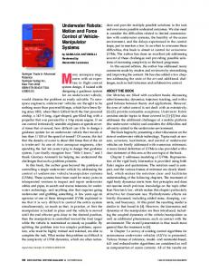
Detail of the C-obstacles
15
Time consumed by the algorithm vs. obstacles boundary
In order to evaluate the behavior at large resolution, evaluations with resolution of 1024 for spatial coordinates and 256 for angular coordinates have been executed on a PC with 512 Mbytes of memory. They reveal that an evaluation with the FFT method is impossible and runs out of memory, but with the proposed hierarchical method it is correctly performed. In figure 5 it is shown the result of one of those executions for the workspace shown in the box. The robot is also represented by the gray small rectangle in the workspace. There, it can be observed the typical shape of three-dimensional C-obstacles. Also, as the C-space is represented by hierarchical data structures the subdivisions of the space at the C-obstacles are shown. To have a better view of this division, a detail of the obstacles is shown in figure 6.
It has been introduced an algorithm to compute the configuration space for a mobile robot using hierarchical representations of the workspace and the robot. Then, a great compactness of data is obtained, allowing to represent bigger areas or to use higher resolutions. In the same way, the algorithm is also hierarchical refining the resolution of the C-space in those regions where more information is needed, i.e, where C-obstacles are placed. The advantage respect other discrete algorithms comes with the efficient management of memory since at high resolutions only surroundings of C-obstacles are considered and not the whole space. Thus, only surroundings of C-obstacles are evaluated at high resolutions so a great dependence with the environment has been detected. The independence with the environment was one of the better aspects of other discrete methods, they only depends on the resolution used and not the size or number of obstacles. So, this advantage has been lost but the independence with shape or complexity of obstacles is maintained. Then, it can be inferred that, when a reduction of memory in discrete methods is desired, a dependence with the environment appears, what becomes clear considering that memory uses by hierarchical structures depends on the data they represent. R EFERENCES [1] T. LozanoPérez, “Spatial planning: A configuration space approach,” IEEE Transactions on Computers, vol. 32, pp. 108–120, Feb. 1983. [2] M. Sharir, “Efficient algorithms for planning purely translational collision-free motion in two an three dimensions,” in Proceedings of the IEEE International Conference on Robotics and Automation, 1987, pp. 1326–1331. [3] R. C. Brost, “Computing metric and topological propierties of configuration-obstacles,” in Proceedings of the IEEE Conf. on Robotics and Automation, 1989, pp. 170–176. [4] L. E. Kavraki, “Computation of configuration-space obstacles using the fast fourier transform,” IEEE Tr. on Robotics and Automation, vol. 11, no. 3, pp. 408–413, 1995. [5] S. Bohn and E. Thornton, “Environment reconstruction for robot navigation,” in Proceeding of the SPIE, vol. 2217, Apr. 1994, pp. 96–106.
3438
Workspace
C-space Fig. 5.
C-obstacles evaluated with the proposed algorithm
[6] T. Hong, S. Balakirsky, E. Messina, T. Chang, and M. Shneier, “A hierarchical model for an autonomous scout vehicle,” in Proceedings of the SPIE, vol. 4715, Apr. 2002. [7] K. Fujimira and H. Samet, “A hierarchical strategy for path planning among moving obstacles,” IEEE Trans. on Robotics and Automation, vol. 5, no. 1, pp. 61–69, Feb. 1989. [8] Y. Kitamura, T. Tanaka, F. Kishino, and M. Yachida, “3-d path planning in a dinamic environment using an octree and an artificial potential field,” in Proceedings of the Int. Conf. on Intelligent Robots and Systems, 1995, pp. 474–481. [9] Y. Yu and K. Gupta, “Sensor-based probabilistic roadmaps: Experiments with an eye-in-hand system,” Journal of Advanced Robotics, vol. 14, no. 6, pp. 515–536, Dec. 2000. [10] D. Jung and K. Gupta, “Octree-based hierarchical distance maps for collision detedtion,” Journal of Robotic Systems, vol. 14, no. 11, pp. 789–806, Nov. 1997. [11] A. Yahja, A. Stentz, S. Singh, and B. Brumitt, “Framed-quadtree path planning for mobile robots operating in sparse environments,” in IEEE Conf. on Robotics and Automation, May 1998. [12] D. Chen, R. Szczerba, and J. Uhran, “Using framed-octrees to find conditional shortest paths in an unknown 3-d environment,” Dep. of Computer Science and Engineering. University of Notre Dame, Tech. Rep. 95-9, 1995. [13] J. Rosell and P. Ifiiguez, “A hierarchical and dynamic method to compute harmonic functions for constrained motion planning,” in Proceedings of the 2002 IEEE/RSJ, Oct. 2002, pp. 2335–2340. [14] P. Iñiguez and J. Rosell, “Probabilistic harmonic-function-based method for robot motion planning,” in Proceedings of the 2003 IEEE/RSJ Intl. Conf. on Intellignet Robots and Systems, October 2003, pp. 382–387. [15] C. Geem, “Fast planning of a good path for a manipulator using potential fields on a non-uniform grid in c-space,” Ph.D. dissertation, Johannes Kepler Universität Linz, May 1996. [16] B. Curto, V. Moreno, and F. Blanco, “A general method for c-space evaluation and its application to articulated robots,” IEEE Trans. on Roboticas and Automation, vol. 18, no. 1, pp. 24–31, feb 2002.
3439