2014 IEEE/RSJ International Conference on Intelligent Robots and Systems (IROS 2014) September 14-18, 2014, Chicago, IL, USA
Fully Omnidirectional Compliance in Mobile Robots Via Drive-Torque Sensor Feedback Kwan Suk Kim1 , Alan S. Kwok1 , Gray C. Thomas1 , and Luis Sentis1 Abstract— In order to make unintentional physical interaction with robots safer for humans, we consider compliant control of an omnidirectional wheeled base. In this paper we present a fully holonomic mobile robot system which achieves compliant motion via force control, improving over previous pseudo-omnidirectional mobile systems by being fully omnidirectional. We explain our robot’s drive train, and present an experimental validation of our actuator control strategy. Using a smith predictor and a simple delay-based plant model, we demonstrate compliance and safe interaction in both the mobile system alone and as the base of a wheeled mobile manipulator style system.
I. INTRODUCTION As humanoid robots move out of the laboratory and into the homes and workplaces of the world, their safe physical interaction with humans will be of utmost importance. Robots, with their fallible sensors and perception will need to tread gently in a world they can barely comprehend to avoid catastrophe. We study the compliance of omnidirectional wheeled bases for humanoid robots to facilitate this transition. Compliance has long been a common feature in robots designed to support humans as they are walking. And these robots are very successful at responding to physical human interaction. Using a force sensitive joystick or handle, these robots are pushed and pulled at the discretion of their often elderly users while providing vertical support and sometimes lateral support in one direction [18], [11], [3], [21], [15]. Such robots have used position or velocity controlled wheeled bases to accomplish their admittance control strategy. A similar, but more complex, strategy employed by the manipulation community uses all the joints of a mobile manipulator in an impedance control scheme, including current controlled 2-DOF caster wheels, to achieve precise impedance control of an end effector [12]. This approach produces a very compliant end effector position, but will not notice a collision occurring on any other portion of its body. Another design in the field of medical robots allowed a bed/wheelchair robot, RHOMBUS [17], to operate with an admittance controller which uses the force experienced by sensitive bumpers on the sides of the robot’s base to dock into tight spaces. The robot maneuvered with a fully omnidirectional sphere tire drive system, allowing it full planar motion freedom to control its bumper forces. This strategy has great potential for robot safety in part due to the 1 The authors are with the Department of Mechanical Engineering, University of Texas at Austin, Austin, TX 78712, USA
[email protected],
[email protected],
[email protected],
[email protected] 978-1-4799-6934-0/14/$31.00 ©2014 European Union
addition of bumpers, which due to their low inertia provide a much safer contact surface for high speed impacts. However this robot was designed for reliable docking and not for unexpected collisions; the bumpers do not extend all the way to the ground, and a human operator is constantly controlling the robot via joystick. A more intentionally safe mobile robot, DLR’s Rollin’ Justin [7], uses force sensitive joints in its upper body to lower the Cartesian impedance of every rigid link rather than just one end effector or a pair of force sensitive bumpers. On the other hand, Rollin’ Justin’s base itself is limited to admittance control. This means that while the upper body is quite compliant, the lower body cannot sense contact itself. The Rollin’ Justin robot benefited from a deep field of literature on the design of compliant actuators and their safety benefits. Collision detection and safe reaction through proprioceptive sensor feedback had been studied in [4] using the the DLR-III Lightweight Manipulator Arm in a shared human-robot workspace. To ensure safety, the controller used the joint torques to identify sudden changes in energy dissipation and treated them as collision events. Depending on the system properties, collisions can also be detected by much simpler methods such as spikes in torque [2]. But detecting collision is not the entirety of a strategy for human robot collision safety. As shown by [8], the head and neck of a person are much harder to protect against robot bludgeoning injury compared to the softer arms and chest. This result is due to the speed at which the robot can decelerate its joints, and the high joint impedance which leads to a high impact collision. The low impedance behavior of actuators in human collisions has been an important topic in the field of robot actuator design. A brief review of the various methods of adding compliance to actuators in order to limit their high frequency impedance is presented in [10]. This high frequency impedance, which is essentially the open loop impedance of the system above the controller bandwidth, can also be improved by increasing the control bandwidth by clever use of two very different actuators in parallel [24]. These strategies have the potential to make collisions with lightweight robot limbs much less dangerous by decoupling the inertia of the rest of the robot from that of the colliding limb. However, using rigid actuation for the base of a wheeled humanoid sacrifices little, since wheeled robot masses in the range of 90 to 250 Kg with stiff metal frames will dwarf the impedance of most human body parts. Perhaps the most effectively safe humanoid base seen thus far in the literature is the pseudo-omnidirectional Azimut-3
4757
[5] robot, which is equipped with four 2-DOF wheel systems, for a total of 8-DOF. Each wheel system consists of a velocity controlled wheel and a force sensitive steering arm. It uses its force sensitive steering joints to estimate the external force being applied to it, with the caveat that the force sensing cannot detect forces pointing towards its instantaneous pivot point, and has low sensor fidelity for forces pointed close to that point. The estimated external force is used to control the steering angle and velocity set-points such that the robot is responsive to even very gentle pushes. However, such a robot could, moving nearly parallel to a wall, crush a person without sensing the extra actuator effort required to crush them. While clever and effective, force sensing of this type still has a critical safety flaw in its singularity and the region of extremely low signal fidelity surrounding it. In designing our force controller for Trikey, we have bypassed this complexity by using a fully holonomic, omnidirectional-wheel based design without singularities. It is our understanding that this is the first time an omnidirectional robot has been outfitted with sensitive force control based on direct measurement of torque instead of motor current. We explain our strategy for simple, high bandwidth force feedback using noisy load cells, and present experiments demonstrating the effectiveness of the design.
Control PC
Ethercat Slave
dsPIC
10kHz
Ethercat Master
Ethercat SPI Analog Digital PWM I 2C
Ethercat Slave
Encoder
dsPIC 2kHz Amp
Low Latency Loop
Torque Sensor
BLDC Motor
Fig. 1. The Electronic system for the actuators are connected to the control PC throught EtherCAT. Each actuator has a 16-bit microcontroller, which can run a simple control loop. There is a 1kHz I2 C bus channel between the torque sensor controller and the motor controllers, so a low latency force feedback loop can be completed throught the channel (Gray Loop).
II. DESIGNING A BASE WITH TORQUE SENSORS A. Trikey: An Omni-directional mobile robot Trikey is an omni-directional, holonomic mobile robot designed for precise mobile manipulation on uneven terrain, while serving as an attachment to an upperbody humanoid.[19] [13] 1) Electronics: The main controller runs on a small form factor computer (Control PC in Fig. 1) with a mobile I7 processor. All the actuators in the mobile base and humanoid upperbody are connected to the main controller via an EtherCAT communication bus. Each of these EtherCAT slaves communicates with a 16bit dsPIC microcontroller through an SPI bus. (Fig. 1). 2) Actuations: The wheels are driven by brush-less DC motors with a 50:1-ratio Harmonic drive. A torque sensor is placed in each drivetrain between the motor and the wheel, so the motor torque or external input can be measured and used by the force controller. 3) Communication Delay: The motor command from the main controller is sent to the actuators every 1 ms, but it takes 5 ms for the command to be implemented at the microcontroller level. On the other hand, the microcontroller has a an internal 500µsec control loop with no time delay. In short, there are two-layers of control loops: the high latency main controller and the low latency microcontrollers. Since torque feedback is sensitive to time delay in the system, the measured torque data is directly sent from the sensor microcontroller to the actuator microcontrollers via I2 C bus every 1 msec. The torque sensors output their measurements as analog signals, and 12-bit AD converters digitize and send these signals to the sensor microcontroller every 100µsec.
Fig. 2. Force Control Testbed: This alternate configuration for Trikey’s drivetrain components facilitates testing with various load inertias. The drivetrain can be modelled as a mass-spring-damper system with two torque sources, the motor torque (τm ) and the external torque (τext ). The torque sensor is modelled as a spring and the displacement in the spring (x1 − x2 ) is proportional to the sensed torque
This sensor microcontroller implements a 1kHz 2nd-order Butterworth low-pass filter for each torque signal. B. The Actuator Testbed To investigate the system dynamics and time delay in detail, we built a testbed which has a similar configuration to the actuators in the mobile base (Fig. 2). The output shaft of the testbed can be connected to various loads with known inertia values. The shaft can also be rigidly affixed to the frame to measure stall torque and to observe the system response to a nearly infinite inertia. When the load is fixed, the open-loop step torque is measured, as shown in Fig. 3. From the graph, the system react to the input signal with a dead time of 5msec, and the torque settles down in 40msec, implying that the system dynamics have a relatively long time constant compared to the servo rate. III. ACTUATOR CONTROL WITH TIME DELAYS The bandwidth of compliant behavior in rigid actuators is limited by the delay between the control action and the sensing of that action’s effect [23]. In the past the Smith
4758
40
Torque (Nm)
35 30 25 20 15
Torque input Torque sensor data Model Approximation
10 5 0 -5
0
0.01
0.02
0.03
0.04
0.05
0.06
Time (s) Fig. 3. Approximate system plant as constant gain and delay: the pure delay and continuous dynamics of the system are modeled using only a constant gain, G, with a time delay d
predictor algorithm [20] has been used to push out the bandwidth of force and impedance controllers under similar conditions [6], [9]. Observing the destabilizing nature of finite difference feedback in discrete time controllers of continuous delay systems with fast time constants relative to the latency [9], Trikey’s controller uses only proportional force feedback, and a smith predictor that assumes a constant gain delayed plant. This controller is run on the embedded digital signal processors to minimize latency. A. Ideal torque controller with a disturbance A simple torque command u(n) with a torque feedback τs can be implemented as follows: u(n) = Kf f τd(n) + Kp [τd(n) − τs(n) ],
a quasi-polynomial expression. To simplify the problem, we approximate the system response as a constant gain, G, and the constant time delay, d as Fig. 3. Then, the torque sensor data can be estimated as follows: τs (n) = G u (n − d) + τext (n) ,
(2)
(5)
u (n) = Kf f τd (n) + Kp [τd (n) − G u (n − d) − τext (n)] 1 Kp Kp = τd (n) − τext (n) + ∆u (n) G 1 + Kp G 1 + Kp G (6) where ∆u (n) = u (n) − u (n − d) and Kf f = 1/G. If the control loop is fast enough and we can assume that τext (n) ≈ τext (n − d), then the torque sensor data will be expressed as follows:
(1)
Where τd , Kf f and Kp are the desired torque, the gain for the feedforward term, and the gain for the proportional feedback. The idealized plant model for each actuator, neglecting force sensor compliance, can be represented as a constant gain G and a disturbance τext as: τs (n) = Gu(n) + τext (n)
Fig. 4. Torque controller with Smith predictor removes the effect of the previous control input, which causes the system to go unstable
τs = τd (n − d)−
1 Kp G τext (n)+ ∆u (n) (7) 1 + Kp G 1 + Kp G
The unexpected term with ∆u approaches to 1 as the proportional gain Kp increases. Moreover, the term will accumulate in every control loop, so the system can become unstable. C. Smith predictor
From Eq. (4), as the gain Kp increases, the effect of the disturbance τext decreases. If a digitized system is not considered [23], ever higher gains appears to guarantee ever improving performance.
To remove the effect of the unexpected term, compensating terms are needed. Fortunately, the previous u (n − d) is known to the controller, so the compensator can be implemented by estimating the coefficient of the u (n − d) ˆ term. The constant gain of the plant, G is estimated as G. ˆ To remove u (n − d), the Smith predictor adds Gu (n) − ˆ (n − d) to u (n) as in Fig. 4. Then, the torque command Gu u can be described as follows: i h 1 ˆ − G)ud − Kp τext u= (Kf f + Kp ) τd + Kp (G ˆ 1 + Kp G (8) ˆ then Eq. (8) approximates where ud = u (n − d). If G ≈ G, Eq. (3).
B. Time Delayed Feedback Torque Controller
D. Simulation
In real robots, mechanical or electrical impedance effects tend to act like a low pass filter at high frequencies, causing the simple proportional torque controller in Eqs. (3) to fail at high gains. Time delays behave in much the same way. To accurately model the effect of feedback delay and higher order system dynamics we would need to find the roots of
To check whether the predictor can improve the system performance, we simulate the system with the P-controller with and without the predictor, as shown in Fig. 5. The system is modelled as a simple mass-spring-damper system shown in Fig. 2, and the system parameters are estimated from the step and frequency response of the testbed. The
Merging Eqs. (1) and (2), and defining Kf f as 1/G, the torque command and the torque feedback can be expressed as follows: Kp 1 τext (3) u (n) = τd − G 1 + Kp G 1 τext (4) τs (n) = τd + 1 + Kp G
4759
10
18
1.5
Joint position Sensed torque 1
With Compliance
0
-2.5 -5
External Input No Controller
-7.5 -10
6
0.5
0
0
-6
-0.5
-12
Torque (Nm)
2 1.6 1.2 0.8 0.4 0 -0.4 -0.8 -1.2 -1.6 -2
Without Compliance
-18
Joint Position (rad)
12
5 2.5
Torque (Nm)
Torque (Nm)
7.5
-1
0
5
10
15
20
25
30
35
-1.5
Time (s) Fig. 6. Zero Torque Control is implemented by sending τd = 0 to the force controller. Then, the controller tries to follow the external force.
Max Gain P-Controller Unstable P-Controller P-Controller with Smith Predictor 0
200
400
600
800
1000
B. Zero Force Control in the Testbed
Time (ms) Fig. 5. The drivetrain simulation with a sinusoidal external force: A sinusoidal external torque is applied to the system, and the system complies with the torque.
controllers apply a motor torque to the system with a delay of 5ms. In the simulation, a sinusoidal external torque with amplitude of 10Nm is applied to the system. When there is no controller, the system follows the torque source with phase lag. As we increase the Kp gain in the P-controller, we can see that the sensed torque decreases, which means the system complies with the external torque. However, when Kp exceeds a value around 4[N/N], the system becomes unstable, indicating that it is the maximum compliance the controller can generate. On the other hand, with Smith predictor, the Kp gain can be further increased, and the system becomes more compliant when applying the external force. IV. EXPERIMENTS A. Experimental Setup Typically, systems with long time delays uses PI controllers rather than PID controllers because the derivative term becomes destabilizing in such systems [9]. Therefore, we use a PI controller in the force controller. The I-term was added to the control system shown in Fig. 4. This force controller runs on the microcontroller every 2kHz, and in the test bed experiments it receives its force setpoints from a simple impedance controller simulating a very soft spring. This impedance controller runs on the control PC at an update rate of 1kHz. We attached a 13.6kg weight with an inertia of 0.71kgm2 to approximate the mobile robot inertia. To analyse the compliant performance of the mobile robot, we used a motion capture system as a global position sensor [13]. The precision of the motion capture system is 1mm.
To identify the compliance of the testbed, we set the desired force to zero. We applied an arbitrary force trajectory manually to the weight, while measuring the joint angle and torque. The result is shown in Fig. 6. Without the force controller, around 15Nm is needed to rotate the load by ±1rad. Even though the drivetrain is considered backdrivable, there is a large and considerable friction in the high gear-ratio Harmonic drive. With the controller active, only 3 − 5Nm is needed to rotate the load, which is 3 − 5 % of the actuator maximum torque, 100Nm. C. Force Control with Step Input in the Testbed In this experiment, we applied a constant desired torque to the force controller for 0.4sec. The graph in Fig. 7 shows the result. The joint angular velocity increases with approximately constant acceleration during the step torque. The joint velocity shows small ripples because the torque sensor data has huge oscillations caused by the Harmonic drive’s torque ripples. Hence, the oscillation only occurs during load movement, and the period is half of the input shaft [16]. However, even though the Harmonic drive generates this torque ripples, the torque controller compensates for the effect and makes the system stable. In the graph, the filtered torque sensor data are filtered by a 10Hz cutoff frequency Butterworth low-pass filter. They show that the controller tried to follow the desired torque. When the desired torque is zero, negative torque sensor data are measured. The negative torque data shows that the friction from the wheel is applied to the drivetrain. That means that the friction is also included in the external force to which the controller should be compliant. D. Simple Low Impedance Control with Inner Force Controller in the Testbed In this experiment, we attach a simple low impedance controller to the force controller, and the output of the position controller is fed into the force controller as an input. The system dynamics is simplifed without any damping
4760
Desired torque Sensed torque Filtered torque
2.5 0
-2.5 -5
0 -5
1.5
0.6
0.4
0.2
0
0
0
0.2
0.4
0.6
0.8
1
Desired position Joint position
1 0.5 0
-0.5 -1
-1.5 -2
-2.5 -0.5
1.2
0
0.5
1
1.5
Time (s)
2
2.5
3
3.5
4
4.5
5
Time (s)
Fig. 7. Step Torque Input Response: A constant desired torque is applied to the controller for 0.4sec (The shaded period). The torque sensor data are filtered by 10Hz cutoff frequency Buttworh low-pass filter to show a trend.
Fig. 8. Simple Low Impedance Control shows a low natural frequency of 0.4Hz. 150
term. The controller consists of only a proportional term, which means the outer controller is equivalent to a spring. The result is shown in Fig. 8. The joint angle trajectory shows a typical undamped mass-spring-damper dynamics. Approximately, we can figure out the equivalent spring stiffness from the frequency of the oscillation, 0.4Hz. If we assume the frequency is the same as the natural frequency q k m , then the equivalent spring stiffness k = 4.47Nm/rad, which is a low impedance for systems with high friction.
Force (N)
100
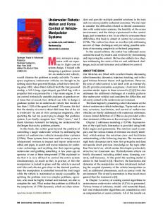
where τk is the measured torque from the torque sensor on k-th drivetrain, and fx , fy , τz are the external force from the front, the external force from the side, and the rotating external force, respectively. r is the radius of each wheel, and R is the distance from the center of the robot to the wheels. We apply forces manually from different directions and measure the torque data while the mobile robot is not operational. The result shown in Fig. 9 proves that the torque sensors located on the drivetrains can detect the external forces precisely.
100
50
50
0
0
-50
-50
-100
-100
-150
E. External Force Estimation on the Mobile Robot Unlike other compliant mobile robots which can sense external forces with their body frame, our mobile robot senses the external force directly from the drivetrain. Therefore, all the external forces in the body can be picked up by the torque sensors (e.g. the external forces normal to the ground cannot be detected). Because the actuation of the robot is holonomic, the external force is estimated easily by the combination of the torques from the torque sensors as follows: τ0 0 − cos(π/6) cos(π/6) fx 1 fy = 1 − sin(π/6) − sin(π/6) τ1 (9) r R R R τ2 τz
150
X-dir Y-dir Rotation
Torque (Nm)
0.4
Joint Position (rad)
Joint position Joint velocity
0.8
Joint Velocity (rad/s)
Joint Position (rad)
5
-10
1.2
-0.2
Desired torque Sensed torque Filtered torque
10
Torque (Nm)
Torque (Nm)
5
Back/Forth 0
5
Left/Right 10
15
Rotate 20
-150 25
Time (s) Fig. 9. The Estimated Force/Torque from the Torque Sensors shows that there are external forces from front, back, left, and right, and external torque rotating the frame.
F. Force Feedback Based Compliance of Trikey We also conduct the zero force control experiment that we did in IV-B in the mobile robot. We run the actuators in the mobile robot in zero force control mode. The motion capture system measures the position and the orientation of the robot. We conduct one directional compliance test. All the actuators run the zero force control previously described and the user applies external forces by pushing and pulling the base. The result in Fig. 10 shows that the acceleration and the estimated force have a similar trend. Also, the mobile base shows compliant movement. However, we did not completely remove the passivity that originates from the robot mass and the friction between the ground and the wheels, so the degree of compliance still needs to be improved. We also made a trial of involving human-robot collision test. We plan an unexpected collision scenario, conduct it,
4761
200 100
0
0
-20
-100
Free Moving
-40
-200
Accel (m/s^2)
900 600 300
60
Acceleration Estimated Force
40 20
0
0
-300
Manual Pushing
-600 -900
R EFERENCES
Velocity (cm/s)
20
Position Velocity
-20
Force (N)
Position (cm)
40
-40 16.5
17
Time (s)
17.5
-60
Fig. 10. The Estimated Force and the Odometry during the Compliant Motion: The position of the robot is measured from the motion capture system. The estimated force is estimated from the sensed torque data. The velocity and the acceleration are derived from the position.
and observe the collision. Fig. 11 shows that the mobile robot becomes more stable with the compliance when it collides with human. Also, to show its omni-directinoal compliance, we push the robot in different directions. V. DISCUSSION AND FUTURE WORK We have retrofitted the holonomic Trikey robot with torque sensing to allow a fully omnidirectional compliant behavior, the first of its kind. We have implemented a predictive controller on the embedded hardware in order to improve the reaction time and bandwidth of our force controller. And we have carried out experiments to demonstrate the safety and compliance of the Trikey sytem, both alone and serving as a base for a humanoid upper body. Compliance is one of the most important features necessary for mobile robots to safely cooperate with humans in human environments. Our work does however leave some unaddressed questions. To achieve our ultimate goal of total mobile safety, we still need to pursue more in terms of performance. For instance, while our force controller effectively hides the passivity of the actuator friction, the friction of the robot on the wheel bearings still causes the system to be highly damped. Friction modelling should be able to allow less damped behavior in the future. Another goal is to improve over compliant zero force control by implementing impedance control. Also, since Trikey’s actuators are rigid, it relies on high bandwidth control to mitigate the damage to a person in the event of a collision, but is unable to improve the highest frequency impedance without the addition of a lower impedance component between it and the human. In our experiments the high frequency impedance is low pass filtered by soft tissue acting as a damped spring-mass system, but to make the human robot interaction experience less painful, soft foam will be added as future work. Finally, there is an opportunity to improve our force controller by modelling and predicting the torque ripples effect endemic to Harmonic drives.
[1] Alin Albu-Sch¨affer, Christian Ott, and Gerd Hirzinger. A unified passivity-based control framework for position, torque and impedance control of flexible joint robots. The International Journal of Robotics Research, 26(1):23–39, 2007. [2] Chang-Nho Cho, Joon-Hong Kim, Young-Loul Kim, Jae-Bok Song, and Jin-Ho Kyung. Collision detection algorithm to distinguish between intended contact and unexpected collision. Advanced Robotics, 26(16):1825–1840, 2012. [3] Oscar Chuy, Yasuhisa Hirata, and Kazuhiro Kosuge. Active type robotic mobility aid control based on passive behavior. In Intelligent Robots and Systems, 2007. IROS 2007. IEEE/RSJ International Conference on, pages 165–170. IEEE, 2007. [4] Alessandro De Luca, Alin Albu-Schaffer, Sami Haddadin, and Gerd Hirzinger. Collision detection and safe reaction with the dlr-iii lightweight manipulator arm. In Intelligent Robots and Systems, 2006 IEEE/RSJ International Conference on, pages 1623–1630. IEEE, 2006. [5] Julien Fr´emy, Franc¸ois Michaud, and Michel Lauria. Pushing a robot along-a natural interface for human-robot interaction. In Robotics and Automation (ICRA), 2010 IEEE International Conference on, pages 3440–3445. IEEE, 2010. [6] Eckhard Freund and J¨urgen Pesara. High-bandwidth force and impedance control for industrial robots. Robotica, 16(01):75–87, 1998. [7] Matthias Fuchs, Christoph Borst, Paolo Robuffo Giordano, Andreas Baumann, Erich Kraemer, J¨org Langwald, Robin Gruber, Nikolaus Seitz, Georg Plank, Klaus Kunze, et al. Rollin’justin-design considerations and realization of a mobile platform for a humanoid upper body. In Robotics and Automation, 2009. ICRA’09. IEEE International Conference on, pages 4131–4137. IEEE, 2009. [8] Sami Haddadin, A Albu-Schaffer, Alessandro De Luca, and Gerd Hirzinger. Collision detection and reaction: A contribution to safe physical human-robot interaction. In Intelligent Robots and Systems, 2008. IROS 2008. IEEE/RSJ International Conference on, pages 3356– 3363. IEEE, 2008. [9] Tore Hagglund. A predictive pi controller for processes with long dead times. Control Systems, IEEE, 12(1):57–60, 1992. [10] R v Ham, Thomas Sugar, Bram Vanderborght, Kevin Hollander, and Dirk Lefeber. Compliant actuator designs. Robotics & Automation Magazine, IEEE, 16(3):81–94, 2009. [11] Yasuhisa Hirata, Takahiro Baba, and Kazuhiro Kosuge. Motion control of omni-directional type walking support system. In Robot and Human Interactive Communication, 2003. Proceedings. ROMAN 2003. The 12th IEEE International Workshop on, pages 85–90. IEEE, 2003. [12] Oussama Khatib. A unified approach for motion and force control of robot manipulators: The operational space formulation. Robotics and Automation, IEEE Journal of, 3(1):43–53, 1987. [13] KS Kim, AS Kwok, and L Sentis. Contact sensing and mobility in rough and cluttered environments. In Mobile Robots (ECMR), 2013 European Conference on, pages 274–281. IEEE, 2013. [14] Andreas Kugi, Christian Ott, A Albu-Schaffer, and Gerd Hirzinger. On the passivity-based impedance control of flexible joint robots. Robotics, IEEE Transactions on, 24(2):416–429, 2008. [15] Oh-Hun Kwon, Hyunsoo Song, and Dong-Soo Kwon. A mobile robot platform based on spring loaded casters for physical interaction. In RO-MAN, 2011 IEEE, pages 156–161. IEEE, 2011. [16] Yu-Sheng Lu, Shuan-Min Lin, Markus Hauschild, and Gerd Hirzinger. A torque-ripple compensation scheme for harmonic drive systems. Electrical Engineering, pages 1–9, 2012. [17] Stephen Mascaro and H Harry Asada. Docking control of holonomic omnidirectional vehicles with applications to a hybrid wheelchair/bed system. In Robotics and Automation, 1998. Proceedings. 1998 IEEE International Conference on, volume 1, pages 399–405. IEEE, 1998. [18] Angelo M Sabatini, Vincenzo Genovese, and Elena Pacchierotti. A mobility aid for the support to walking and object transportation of people with motor impairments. In Intelligent Robots and Systems, 2002. IEEE/RSJ International Conference on, volume 2, pages 1349– 1354. IEEE, 2002. [19] Luis Sentis, Josh Petersen, and Roland Philippsen. Experiments with balancing on irregular terrains using the dreamer mobile humanoid robot. In Robotics: Science and Systems, 2012. [20] Otto JM Smith. A controller to overcome dead time. ISA Journal, 6(2):28–33, 1959. [21] Matthew Spenko, Haoyong Yu, and Steven Dubowsky. Robotic personal aids for mobility and monitoring for the elderly. Neural Systems
4762
(a) Colliding with compliance
(b) Colliding without compliance
(c) Passing the robot Fig. 11. Experiments on Compliant Mobile Robot: a compliant mobile base is implemented by the zero force controller in the actuators. (a) The mobile robot is compliant during an unexpected collision with a human. (b) The mobile robot tips over due to a human collision while the force controller is disabled. (c) The compliance is omni-directional, so the robot can be passed in any direction.
and Rehabilitation Engineering, IEEE Transactions on, 14(3):344– 351, 2006. [22] Heike Vallery, Ralf Ekkelenkamp, Herman Van Der Kooij, and Martin Buss. Passive and accurate torque control of series elastic actuators. In Intelligent Robots and Systems, 2007. IROS 2007. IEEE/RSJ International Conference on, pages 3534–3538. IEEE, 2007.
[23] Shang-Teh Wu. Digital high-gain pd control of robot manipulators. Journal of Robotic Systems, 14(5):375–387, 1997. [24] Michael Zinn, Bernard Roth, Oussama Khatib, and J Kenneth Salisbury. A new actuation approach for human friendly robot design. The international journal of robotics research, 23(4-5):379–398, 2004.
4763