Markus Ulrich, Christian Wiedemann, and Carsten Steger. Abstractâ This ...... 345â350. [24] M. S. Paterson and F. F. Yao, âEfficient binary space partitions for.
CAD-Based Recognition of 3D Objects in Monocular Images Markus Ulrich, Christian Wiedemann, and Carsten Steger
Abstract— This paper provides a method for recognizing 3D objects in a single camera image and for determining their 3D poses. A model is trained solely based on the geometry information of a 3D CAD model of the object. We do not rely on texture or reflectance information of the object’s surface, making this approach useful for a wide range of industrial and robot applications and complementary to descriptor-based approaches. A view-based approach that does not show the drawbacks of previous methods is applied: It is robust to noise, occlusions, clutter, and contrast changes. Furthermore, the 3D pose is determined with high accuracy. The high robustness of an exhaustive search is combined with an efficient hierarchical search, a high percentage of which can be computed offline, making our method suitable even for time-critical applications. The method is especially suited for, but not limited to, the recognition of untextured objects like metal parts, which are often used in industrial environments. It allows, for example, 3D pin picking in robot applications. Tracking approaches can use it for initialization.
I. INTRODUCTION In industrial or robot applications, often untextured objects like the two metallic clamps shown in Fig. 1(a) must be recognized in monocular images. Obviously, the automation level of many industrial processes could be improved significantly if the pose of such objects could be determined reliably. However, there is no published technique that is able to robustly recognize an untextured 3D object in a monocular image in a reasonable amount of time. Thus, e.g., the problem of making a robot pick up objects with an unknown pose is still not solved in general. Furthermore, often a setup consisting of two or more cameras cannot be used because it is either too expensive, too cumbersome to calibrate, not rigid enough for industrial environments, or simply too bulky. II. RELATED WORK Approaches for recognizing 3D objects in monocular images have been extensively studied. One challenge is the very large six-dimensional search space if the object is imaged from an unknown viewpoint. For a time, view-based approaches were very popular. The search image was compared with precomputed 2D views of the object to determine the object pose ([1], [2], [3], [4]). These approaches tried to deal with the full geometric search space by clustering the views. None of them became accepted in practice. This decreased the interest in this kind of approaches. Some view-based approaches use previous Markus Ulrich, Christian Wiedemann, and Carsten Steger are with MVTec Software GmbH, Neherstr. 1, 81675 Munich, Germany
{ulrich|wiedemann|steger}@mvtec.com
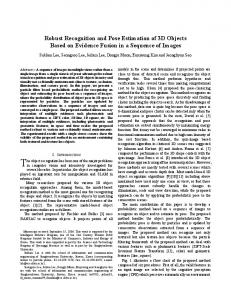
(a)
(b)
Fig. 1. (a) Image of two differently colored metallic clamps in a cluttered environment. Our approach is able to detect these objects reliably. (b) CAD model of the clamp shown in (a) that serves as input for the model generation. For visualization purposes, hidden edges as well as edges between coplanar faces are not displayed.
knowledge to reduce the search space, e.g., [5], which assumes that the object is lying on a conveyor belt and therefore appears in a known distance in front of the camera. Other approaches try to circumvent the large geometric search space. Feature-based approaches ([6], [7], [8], [9]) use features like gray value edges, intersections of straight lines that approximate gray value edges, or more complex features that result from grouping extracted primitives. They assume that these features correspond either to texture edges or to geometric edges or corners of the 3D object. The extracted features are matched to the corresponding 3D object features. Then, the 3D pose of the object is calculated directly from the corresponding points. These approaches circumvent the geometric search space that results from the unknown object pose. However, they must deal with the search space that results from the establishment of the correspondences between the image features and the object features, which can be very large as well. Clutter in the scene increases the amount of extracted features and thus the search space. More complex features can be used to reduce the search space, but then the feature extraction becomes less robust, especially if parts of the object are occluded or object edges are not clearly visible. This makes these approaches unsuitable for real applications. Recent approaches use graphics hardwareaccelerated implementations for speed-up. For example, [10] perform an exhaustive search by implementing the Generalized Hough Transform on graphics hardware. By exploiting the huge parallelization potential they achieve computation times of less than one minute. Despite the great speed-up, it is still too slow for most practical applications. Furthermore, the Generalized Hough Transform shows only a limited robustness to contrast changes because only edges above a pre-defined threshold are taken into account.
Descriptor-based methods ([11], [12], [13], [14], [15], [16], [17]) first create artificial views of the object in which feature points are determined together with discriminative descriptors that are derived from the surroundings of the feature points. Based on these descriptors, a classifier is trained. Then, in the search phase the correspondence between the model and the search image is established by classifying the descriptors derived from the search image. The big advantage of descriptor-based approaches is that their run-time is independent of the size of the geometric search space. They show outstanding performance in several scenarios but they are restricted to the recognition of textured objects because only then meaningful descriptors can be determined. There exist tracking approaches ([18], [19]) that are able to determine the pose of 3D objects based on their geometry. However, they do not need to deal with the above mentioned search space because the approximate object pose is known. III. CHALLENGES AND MAIN CONTRIBUTIONS In this paper, a model is automatically trained from a 3D CAD model after specifying the range of poses in which the object may appear in front of the camera. During the training, only the object’s geometry information that is important for the recognition process is included in the model. The advantage of this approach is that objects with or without textured surfaces can be recognized. The main task of the training is to derive a hierarchy of 2D views of the object that can be used to find the object efficiently in an image. During the recognition, each found object candidate is evaluated and its pose is computed by minimizing a geometric distance measure in the image. One major problem occurs when dealing with such a view-based approach. The six degrees of freedom of an object in 3D space lead to a huge number of 2D views that must be compared to the image. This leads to run-times that are in no way suitable for real applications. Therefore, most view-based approaches try to reduce the complexity by using a view sphere, i.e., precomputing views, for which the camera is placed on the surface of a virtual sphere around the object looking to the center of the object. The advantage of this approach is that only three degrees of freedom are sampled offline: the latitude and longitude of the camera on the sphere, and the radius of the sphere. The resulting views are compared online to the image, where the remaining three degrees of freedom must be considered by translating and rotating the view in the image plane. Unfortunately, for time-critical applications there still are too many views that must be translated, rotated, and compared to the image. Additionally, this approach does not cover the original six degrees of freedom as is often believed: If the object does not appear in the center of the image this view is related to the sampled (centered) view by a 2D projective transformation because the transition between both views corresponds to a rotation of the camera around its optical center. Consequently, to take this effect into account one would additionally have to projectively transform the 2D
view depending on the image position before comparing it to the image, which would introduce a dramatic speed penalty. Ignoring this effect introduces an error that decreases the robustness of the recognition considerably. The first main contribution of this paper is a hierarchical view-based approach that combines a pyramid search with a hierarchy of object views. With this, on the top pyramid level only few views must be investigated. This allows to apply an exhaustive search, which is very robust, but would be too expensive without the hierarchial approach. Furthermore, the above mentioned errors normally introduced when using a view sphere can be compensated. To be able to apply a pyramid approach using image pyramids, the model must be available in different resolutions or generalization levels, respectively. The generalization of a 3D model such that it corresponds to the generalization that is introduced by the use of an image pyramid is very difficult. Furthermore, edges between faces of the model that have a similar face orientation should not be used for the matching. The second main contribution of this paper is an image generation method that projects the geometry of a 3D model into a color image from which a 2D model on different generalization levels can easily be derived and which allows to ignore edges between faces of similar orientation. Finally, view-based approaches have the drawback that the accuracy of the resulting object pose is limited to the density of the sampled views. Therefore, a subsequent pose refinement step is indispensable. Unfortunately, this is a highly non-linear problem that must be solved iteratively. Because the object must be projected online at each iteration, in general this is a very time consuming process. Therefore, the third main contribution of this paper is an efficient way to refine the pose of the object. IV. DETAILED DESCRIPTION OF THE APPROACH A. Geometric camera calibration Geometric camera calibration is a prerequisite for the extraction of precise 3D information from imagery. We assume a pinhole camera with radial distortions. The camera model and the complete calibration process is described in [20]. The radial distortions can easily be eliminated by rectifying the search image. To speed up this rectification, a mapping is computed offline during the generation of the 3D model [21]. B. 3D model generation The input of the model generation step is the triangulated surface of the object model. Fig. 1(b) shows the CAD model of the clamp shown in Fig. 1(a). The object mainly consists of planar surfaces as well as of a cylinder, which is approximated by several planar faces. 1) Hierarchical view generation: For the generation of the 3D model, different views of the object are created within some predefined pose bounds. The views are automatically created by placing virtual cameras around the 3D object and by projecting the object into the image plane of each virtual camera. The object is assumed to be at the center
zw
jmax xw
lmax lmin
zc
dmin yw jmin
dmax
j=0 plane
xc yc
(a)
(b)
(c)
(d)
Fig. 2. Spherical coordinate system of the view sphere. The pose of the world coordinate system (xw ,yw ,zw ) with respect to the camera coordinate system (xc ,yc ,zc ) can be described by longitude (λ), latitude (ϕ), and distance (d). The pose range is described by minimum and maximum values for λ, ϕ, and d.
Fig. 3. Resulting model views on pyramid level 1 (a), level 2 (b), level 3 (c), and level 4 (d). The views are visualized by small square pyramids that represent the cameras.
of a sphere that defines a spherical coordinate system. The virtual cameras, which are used to create the views, are arranged around the object in such a way that they all point to the center of the sphere. The pose range can then be restricted to a certain spherical quadrilateral (see Fig. 2) by specifying intervals for the spherical parameters λ (longitude), ϕ (latitude), and d (distance). The sampling of the views within the pose range is automatically determined during the model generation process to maximize robustness and speed of the recognition. To further increase the speed of the recognition, the model is created on multiple levels of an image pyramid. Because higher pyramid levels allow a coarser sampling of the views, the computation of the views is performed for each pyramid level separately. The view sampling starts on the lowest image pyramid level by applying an over-sampling of the views. Then the similarity between all views of neighboring camera positions is computed by applying the similarity measure that is used in the online-phase (see below). The pair of views with the highest similarity is selected and merged into one view, and the similarities between the new view and its neighboring views are computed. This process is repeated until the highest similarity is below a certain threshold. If no pair of object views whose similarity exceeds the threshold is left, the remaining views are copied into the 3D model. The views computed so far are stored in the lowest (original) pyramid level. In Fig. 3(a), for all views on the lowest pyramid level the corresponding cameras that are obtained when applying the described method to the pose range shown in Fig. 2 are visualized. To derive the views on the next higher pyramid level, the merging is continued while relaxing the similarity constraint. For this, the similarity measure is computed on the sub-sampled image of the corresponding image pyramid level. This automatically relaxes the similarity constraint since smaller dissimilarities
are eliminated by reducing the image resolution. If no pair of object views whose similarity exceeds the threshold is left, the remaining views are copied into the corresponding level of the 3D model. In Fig. 3(b)–(d) the resulting views on higher pyramid levels are shown. In this example, it is sufficient to distinguish only four different views on the fourth pyramid level. Additionally, at each view a reference to all child views is stored. The child views are those views on the next lower pyramid level that have been merged to obtain the view on the current pyramid level or the view that could not be merged. The references are stored in a tree structure. This information is used in the online-phase to query for a given view on a higher pyramid level the views on the next lower pyramid level that are used to refine the matches. A similar idea has been introduced in [22]. However, in contrast to [22] we compute the hierarchy not only over different object shapes (or views in our case) but additionally over different image pyramid levels. 2) Model image generation: After the tree has been completely generated, for each pyramid level and each view on this level, a 2D model is created by using the approach presented in [23]. It uses a similarity measure that is robust to occlusions, clutter, and non-linear contrast changes. The 2D model consists of a plurality of edge points with a corresponding gradient direction vector. The similarity measure is the mean of the absolute values of the dot products of the corresponding normalized edge gradient directions in the model and in the search image (see below). To build the 2D model, the geometry of the object is projected into the image plane using the camera pose that is represented by the current view. Hidden lines are eliminated by using an appropriate hidden-line-algorithm, e.g., [24]. The projection is done in such a way that a 3-channel color image is obtained, where the three channels represent the three elements of the normal
vector of the faces of the 3D object. This has the advantage that the edge amplitude that can be measured in this color image is directly related to the angle in 3D space between the normal vectors of two neighboring faces of the 3D object. Let us assume that the normal vectors of two neighboring faces are n1 = (x1 , y1 , z1 )� and n2 = (x2 , y2 , z2 )� . When creating the 3-channel image, the first face is painted into the image using the color (R 1 , G1 , B1 ) = (x1 , y1 , z1 ) while the second face is painted into the image using the color (R2 , G2 , B2 ) = (x2 , y2 , z2 ). Let us further assume without loss of generality (because of the isotropy of the color tensor, see below) that the two projected faces cause a vertical edge in the image. Then, the first derivatives in row direction are grR = grG = grB = 0 and in column direction are gcR = R2 − R1 , gcG = G2 − G1 , and gcB = B2 − B1 . The edge amplitude in a color image can be obtained by computing the eigenvalues of the color tensor C [25]: � � grr grc C= (1) grc gcc where in the case of a 3-channel image grr
=
grc = gcc =
grR 2 + grG 2 + grB 2 grR gcR + grG gcG + grB gcB gcR 2 + gcG 2 + gcB 2
(2)
Substituting the above derivatives yields: � � 0 0 C= 0 (R2 − R1 )2 + (G2 − G1 )2 + (B2 − B1 )2 (3) Then, the edge amplitude A is the square root of the largest eigenvalue of C, and hence � (4) A = (R2 − R1 )2 + (G2 − G1 )2 + (B2 − B1 )2 Thus, the edge amplitude computed in the image corresponds to the length of the difference vector of the two normal vectors. The two normal vectors (of length 1) span a twodimensional isosceles triangle. Finally, the angle between both normal vectors can be easily derived from the edge amplitude by using the following formula: δ = 2 arcsin(A/2)
(5)
The obtained color image of the projected model serves as the model image and is passed to the model generation step of the approach presented in [23], extended by color edge extraction. First, the edge amplitude in the model image is computed [25]. Only pixels that exceed a certain threshold are included in the model. Often, the 3D description of the model contains many edges that are invisible in a true image of the object. For example, such edges result from triangulation methods of the CAD software that are used to approximate curved surfaces by a sufficient number of planar faces. Consequently, these edges must not be included in the 2D model. For example, the edges of the planar faces that approximate the cylindrical hole in Fig. 1(b) must be suppressed. Because of the relation described above, one can suppress such edges by passing an appropriate threshold for
(a)
(b)
(c)
(d)
Fig. 4. One generated model image (a) and extracted edges after applying a threshold on the color edge amplitude that corresponds to a minimum face angle of 5◦ (b), 15◦ (c), and 50◦ (d).
the minimum face angle δ min , which is very intuitive. Then the minimum angle can easily be transformed to a threshold value Amin that can be applied to the edge amplitude by solving (5) for A. Fig. 4(a) shows the resulting model image of one sample view. In Fig. 4(b) the edges that result when setting δ min = 5◦ , and hence A min = 0.087, are visualized. Because the planar faces that approximate the cylinder occur in 8 ◦ steps, the vertical edges are still visible. The edges that are obtained when setting δmin = 15◦ (Amin = 0.261) are shown in Fig. 4(c). The edges of the cylinder are successfully suppressed. For most models δ min = 15◦ works well and does not need adaptation. Thus, the novel generation of 3channel model images enables the use of existing 2D edgebased matching approaches by simply passing a threshold for the edge amplitude to eliminate edges that are invisible in a real image. It also has the advantage that the problem of generalizing a 3D model when using a pyramid approach becomes unnecessary because the generalization is implicitly done by computing the image pyramid of the model image. Finally, the 2D model is generated from the 3-channel image on the associated image pyramid level (see [23] and [25] for details). The 2D model created on the current pyramid level is automatically rejected if it does not show enough distinct characteristics that are necessary to distinguish the model from clutter in the image (see [21] for details). The 3D model consists of a plurality of 2D models on several pyramid levels. For each 2D model, the corresponding 3D pose is stored. Additionally, 2D models on neighboring pyramid levels are connected in form of the tree described above. C. 3D object recognition In the online-phase the created 3D model is used for recognizing the 3D object in a single camera image and for determining the 3D pose of the object with respect to
the camera coordinate system. First, an image pyramid is built from the input image. The recognition starts at the highest pyramid level on which at least one valid 2D model is available. All 2D models on this pyramid level are searched by computing a similarity measure c [23] between the 2D models of the views and the current image pyramid level. It measures the mean orientation difference between the gradients mi of the n 2D model points and the underlying gradients si in the search image by using the dot product denoted by �., .�: n
c=
1 � |�mi , si �| n i=1 �mi � · �si �
(6)
This measure is robust to occlusions, clutter, contrast changes, and local polarity changes. The 2D models are rotated and scaled in the necessary range and the similarity measure is computed at each position of the scaled and rotated 2D models in the image. The 2D poses (position, rotation, scaling) of matches that exceed a certain similarity threshold are stored in the list of match candidates. On the next lower pyramid levels all 2D models that do not have a parent node in the tree are searched in the same way as the views on the highest pyramid level. Additionally, the match candidates that have been found on the previous pyramid level are refined. The refinement is performed by selecting all child views in the tree and computing the similarity measure between the 2D models of the child views and the current image pyramid level. However, the range of investigated positions, rotations, and scalings can be limited to a close neighborhood of the parent match. This process is repeated until all match candidates are tracked down to the lowest pyramid level. The combination of a pyramid approach with hierarchical model views that are arranged in a tree structure is essential for time-critical applications. Because the 2D models are created during the training by assuming a camera that is directed to the object center, the 2D model and the imaged object are related by a 2D homography. An example is shown in Fig. 5. The black projection shows a view where the camera is directed to the center of the object. From this view, a 2D model was created. During the search, the object might appear in arbitrary image positions, as shown by the red projections in the image corners of Fig. 5. This apparent movement in the image plane in reality corresponds to a rotation of the camera around its optical center. Consequently, the search will fail if the object does not appear close to the image center because during the 2D matching only a similarity transformation is taken into account. Therefore, we transform the 2D model by applying the homography before performing the matching. This is an absolutely essential step that has not been applied in previous view-based recognition approaches. The parameters of the homography are computed based on the position of the object in the image that is approximately known from the next higher pyramid level. Let x be the 2D model point generated by projecting the 3D model into the image plane using a camera that
Fig. 5. Center view of the object (black) and two off-center views (red) that are obtained when rotating the camera around its optical center. Note the significant projective distortions of the off-center views with respect to the center view.
is directed to the model center. Furthermore, let K be the camera calibration matrix and R be a camera rotation matrix that describes the deviation from a model centered view. Then the point x � in the image of the rotated camera is x� = KRK −1x = Hx,
(7)
where H is a homography. The unknown rotation matrix can be derived from the position p = (c, r, 1) of the projected model in the image, which is transformed into a direction P in 3D space by P = K −1 p. The rotation angles of R around the x and�y axis of the camera is computed by α = arctan Py / Pz2 + Px2 and β = arctan Px /Pz , respectively. Finally, the matching is performed with the projectively corrected 2D models of the child views. On the top pyramid level, an exhaustive search must be performed because no previous knowledge is available. Thus, the matching is performed at all image positions. However, projectively transforming the models depending on the current image position would be too expensive. Fortunately, on the highest level in general the projective distortions are very small because of the subsampling that comes with the image pyramid. To further reduce the distortions on the top pyramid level, the planar 2D model as well as the image is mapped to the surface of a sphere before applying the matching on the highest pyramid level. Then, the projection does not change when rotating the camera around its optical center. Unfortunately, there is no mapping from the sphere into the plane without introducing distortions. However, in general these distortions are smaller than the projective distortions. To speed up the spherical mapping of the search image, the mapping is pre-computed offline. The tracking through the pyramid is performed in the original (non-spherical) image as described above. As result of the matching one obtains the 2D poses (position, rotation, scaling) of the 2D matches in the image that exceed a certain similarity measure. For each match, the corresponding 3D object pose is computed based on the 2D matching pose and the 3D pose of the model view that is associated with the match. Let the 3D pose of the model view be expressed as a homogenous 4 × 4 matrix H v , which transforms points from the object coordinate system into the camera coordinate system. Furthermore, the 2D matching
pose is given by p = (r, c, 1) � (position), γ (rotation), and s (scaling). Then the matrix H v must be modified such that it reflects the 2D matching pose. First, the 2D scaling is applied, which is interpreted as the inverse isotropic scaling S of the distance between object and camera. Then, the 2D rotation is applied, which is interpreted as a 3D rotation R z of the camera around its z axis. Finally, the position in the image is interpreted as a 3D rotation of the camera around its x and y axis. The two rotation angles can be computed by transforming the position into a direction in 3D space and subsequently into rotation angles α and β in a similar way as described above. This results in the final homogeneous transformation matrix, which describes the 3D pose of the object with respect to the camera coordinate system: Hv,s,γ,p = Ry (β)Rx (α)Rz (−γ)S(1/s)Hv
first iteration. From the result of the hidden-line algorithm in the first iteration, the two end points of the visible part of each projected model edge are available in the image. Each end point together with the optical center defines a line of sight in 3D. The two lines of sight are intersected with the 3D model edge. The two intersections define the part of the 3D model edge that is visible in the initial pose. In further iterations, not the complete 3D model edge but only the part that was visible in the first iteration is projected. This speeds up the pose refinement significantly because no hidden-line algorithm needs to be applied. In most cases the error that is introduced by this simplification only marginally degrades the obtained accuracy because the initial pose is already close enough to the optimum to prevent significant changes in the perspective.
(8) V. EVALUATION
D. Pose refinement The accuracy of the obtained 3D pose is limited to the sampling of the views and the sampling of the 2D poses during the 2D matching. For practical applications, this is insufficient. The refinement of the 3D pose is performed by using a least-squares adjustment. For this, the 3D object is projected into the search image by using the pose Hv,s,γ,p . During the projection the hidden-line algorithm is used to suppress lines that are invisible in the current pose. In addition, lines that represent object edges at which the angle between the two adjacent object faces is below the specified minimum face angle (see Section IV-B.2) are suppressed. The visible projected model edges are sampled to discrete points using a suitable sampling distance, e.g., 1 pixel. For each sampled edge point, a local search is initiated to find the corresponding subpixel-precise image edge point in the neighborhood of the sampled edge point. The search is restricted to a direction that is perpendicular to the projected model edge. Additionally, for each found potential correspondence, the angle difference between the perpendicular to the projected model edge and the image gradient is computed. Only the correspondences with an angle difference below a threshold are accepted as valid correspondences. Finally, the refined 3D pose is obtained through a robust iterative non-linear optimization using the Levenberg-Marquardt algorithm. During the optimization the squared distances of the image edge points to their corresponding projected model edge are minimized directly over the 6 pose parameters. After the minimization, the refined pose parameters are available. Because from the refined pose parameters new correspondences can arise, the optimization algorithm is integrated within an outer iteration loop. Actually, the model would have to be re-projected using the hidden-line algorithm and the correspondences would have to be re-computed after each iteration. Unfortunately, the hidden-line computation requires a significant amount of computation time, which is too expensive for time-critical applications, especially when using a complex 3D model that consists of many faces. Therefore, the hidden-line algorithm is only applied in the
As a first step of evaluation we simulated various objects. If the search range overlapped the simulated range of poses, they were detected without exception. This is the benefit of the applied exhaustive search. For the evaluations with real objects, we acquired 8 bit gray scale images of size 640 × 480 with a focal length of 8.5 mm, where the objects where placed in a distance range between 150–350 mm in front of the camera. All tests were performed on a 2.33 GHz Intel Xeon E5345. Two different objects (clamp and fuse) were used for the evaluation. The models were created within the pose range λ = ϕ = [−50; +50]◦ and d = [150; 200] mm for the clamp model and d = [250; 350] mm for the fuse model. The number of sampled views on the different pyramid levels are 9989, 1420, 299, 79, 38, and 17 (level 1–6) for the fuse model and 1110, 281, 86, 34, and 16 (level 1–5) for the clamp model. Note the immense reduction of 9989 to 17 views and 1110 to 16 views, respectively, when using our hierarchical approach. To measure the accuracy, we acquired 50 images of each object by moving the camera to different poses. Next to the object, we placed a calibration plate with black circular marks of which the centers are known in world coordinates (see Fig. 6(a) and (b)). We computed the pose of the calibration plate with respect to the camera in each image by using a standard pose estimation algorithm. By determining the mean relative pose of the object with respect to the calibration plate we were able to compute a true pose of the object for each image. This pose was compared to the pose that was returned by our recognition approach. The result is shown in Table I. Note the high accuracy, especially the standard deviation of the position, which is 0.2% with respect to the object distance. The respective values that are obtained when switching off the pose refinement step are displayed in parantheses. The benefit of the pose refinement is evident. To illustrate the difference between our approach and the descriptor-based matching, we compared our approach with the descriptor-based matching approach proposed in [16]. The descriptor model was trained to recognize the object’s plane that provides the most texture information. For the fuse, the accuracy of the results is significantly worse
application ran for three days without the robot missing a single fuse. Last but not least, the exhaustive search on the top pyramid level as well as the tracking of multiple candidates through the pyramid provide a high speed up potential by parallelization. (a)
(b)
Fig. 6. Two of 100 images used to measure the accuracy of the computed object poses. The true pose was obtained by placing a calibration plate with known black circular marks next to the object.
whereas the recognition is faster by a factor of 50. For the clamp, the descriptor-based method was not able to find any instance of the object. These results are very typical: As soon as the object shows significant texture, the descriptor-based methods will find the object quickly. But it is impossible to recognize untextured objects with descriptor-based matching approaches. We also compared our approach with a feature-based approach similar to [26] that uses corresponding 2D-3D points. This approach was in no way robust to clutter and occlusions and especially for cluttered images it was much too slow. The low robustness mainly resulted from the problem of reliably extracting the 2D feature points in scenes with clutter and occlusions. To illustrate the robustness to occlusions, clutter, and contrast changes, in Figs. 7(a) and (b) two example images are shown in which the fuse could be correctly found. Even highly textured objects (Figs. 7(c)), objects with curved surfaces (Fig. 7(d) and (e)), and objects with strong reflections (Fig. 7(f)) can be recognized by the appoach. The breadth-first strategy during the pyramid search allows to find multiple instances of the same object simultaneously without the run-time increasing linearly. The two instances of the clamp object shown in Fig. 1(a), for example, are correctly recognized in 0.3 s despite the high degree of clutter, the strong reflections on the metal surfaces, and the different colors. A video that shows how easy our approach can be used in practice is provided as supplemental material. The approach is able to find objects in gray scale or color images. Tests have shown that the robustness and the speed are higher when using color images because the additional information helps to eliminate false positives in an early stage during the tracking through the pyramid. Future work will include more extensive evaluations including robustness, accuracy, and color information. The major limitation of our approach is that the pose range should not contain any degenerated views of the object, like a side view of an (almost) planar object. The risk to wrongly find such degenerated views is high. For example, the above mentioned side view would be found at each pair of parallel edges in the image. It is also worth noting that our method was already tested in robot applications. For example, it was used to make a robot grab fuses like that shown in Fig. 6(b). This demo
VI. CONCLUSIONS A robust and fast method for recognizing a 3D object in a single camera image and for determining its 3D pose was presented. Only geometry information is used for recognition, and hence no texture information is needed. The novel combination of a pyramid approach with hierarchical model views that are arranged in a tree structure is essential for time-critical applications and has not been applied in previous recognition approaches. The generation of 3-channel model images enables the use of existing 2D edge-based matching approaches by simply passing a threshold for the edge amplitude to eliminate object edges that are not visible in a real image. The projective transformation of 2D models during the tracking is essential for a high robustness of the recognition approach. Finally, a high accuracy is obtained by applying a 3D pose refinement without performing an expensive projection in each iteration. Furthermore, optional methods are provided that efficiently map the model and the image to a spherical projection to eliminate projective distortions on the highest pyramid level that in some cases otherwise would reduce the robustness of the 2D matching. Computation times of a few hundred milliseconds allow even time-critical applications to benefit from our approach.
R EFERENCES [1] W. E. L. Grimson and D. P. Huttenlocher, “On the verification of hypothesized matches in model-based recognition,” IEEE Transactions on Pattern Analysis and Machine Intelligence, vol. 13, no. 12, pp. 1201–1213, Dec. 1991. [2] J. H. M. Byne and J. A. D. W. Anderson, “A CAD based computer vision system,” Image and Vision Computing, vol. 16, no. 8, pp. 533– 539, June 1998. [3] H. Borotschnig, L. Paletta, M. Prantl, and A. Prinz, “Appearance based active object recognition,” Image and Vision Computing, vol. 18, no. 9, pp. 715–727, June 2000. [4] C. M. Cyr and B. B. Kimia, “3D object recognition using shape similarity-based aspect graph,” in 8th International Conference on Computer Vision, vol. I, 2001, pp. 254–261. [5] C. Von Bank, D. M. Gavrila, and C. W¨ohler, “A visual quality inspection system based on a hierarchical 3d pose estimation algorithm,” in Pattern Recognition, ser. Lecture Notes in Computer Science, vol. 2781. Springer-Verlag, 2003, pp. 179–186. [6] D. G. Lowe, “Three-dimensional object recognition from single twodimensional images,” Artifical Intelligence, vol. 21, no. 3, pp. 335–395, 1987. [7] M. S. Costa and L. G. Shapiro, “3D object recognition and pose with relational indexing,” Computer Vision and Image Understanding, vol. 79, no. 3, pp. 364–407, Sept. 2000. [8] P. David and D. DeMenthon, “Simultaneous pose and correspondence determination using line features,” in Computer Vision and Pattern Recognition, 2003, pp. 424–431. [9] P. David and D.DeMenthon, “Object recognition in high clutter images using line features,” in 10th International Conference on Computer Vision, 2005, pp. 1581–1588.
TABLE I R ESULT OF THE ACCURACY EVALUATION
Object Clamp Fuse
σpos [mm] 0.39 (0.87) 0.74 (1.32)
Presented Method σpos [%] σrot [◦ ] 0.20 (0.46) 0.48 (1.02) 0.21 (0.37) 0.60 (0.70)
time [s] 0.32 (0.30) 0.87 (0.50)
σpos [mm] 2.21
Descriptor-Based Method σpos [%] σrot [◦ ] 0.61 1.20
time [s] 0.02
σpos [mm] and σpos [%] are the standard deviations of the position in mm and as percentage with respect to the absolute distance. σrot [◦ ] is the standard deviation of the (Rodriguez) rotation angle in degrees. The mean recognition times over all 50 images are given in seconds. The respective values without applying the pose refinement step are given in parantheses.
(a)
(b)
(c)
(d)
(e)
(f)
Fig. 7. The approach is robust to occlusions, clutter (a) and non-linear contrast changes (b) to a high degree. It is also able to recognize highly textured objects like the beverage carton shown in (c). Even objects with cuved surfaces can be recognized like a pencil sharpener (d) or a football (e). Strong reflections on the object’s surface do not influence the recognition (f). The pose of the found objects is visualized by the blue edges.
[10] R. Strzodka, I. Ihrke, and M. Magnor, “A graphics hardware implementation of the generalized Hough transform for fast object recognition, scale, and 3d pose detection,” in International Conference on Image Analysis and Processing, 2003, pp. 188–193. [11] S. Belongie, J. Malik, and J. Puzicha, “Shape matching and object recognition using shape contexts,” IEEE Transactions on Pattern Analysis and Machine Intelligence, vol. 24, no. 4, pp. 509–522, Apr. 2002. [12] D. G. Lowe, “Distinctive image features from scale-invariant keypoints,” International Journal of Computer Vision, vol. 60, no. 2, pp. 91–110, 2004. [13] A. C. Berg, T. L. Berg, and J. Malik, “Shape matching and object recognition using low distortion correspondences,” in Computer Vision and Pattern Recognition, 2005, pp. 26–33. [14] J. Pilet, V. Lepetit, and P. Fua, “Real-time non-rigid surface detection,” in Computer Vision and Pattern Recognition, 2005, pp. 822–828. [15] H. Bay, T. Tuytelaars, and L. V. Gool, “SURF: Speeded up robust features,” in 9th European Conference on Computer Vision, ser. Lecture Notes in Computer Science, vol. 3951. Berlin: SpringerVerlag, 2006, pp. 404–417. [16] V. Lepetit, “Keypoint recognition using randomized trees,” IEEE Transactions on Pattern Analysis and Machine Intelligence, vol. 28, no. 9, pp. 1465–1479, 2006. [17] S. Hinterstoisser, S. Benhimane, and N. Navab, “N3M: Natural 3D markers for real-time object detection and pose estimation,” in 11th International Conference on Computer Vision, 2007.
[18] H. Kollnig and H.-H. Nagel, “3d pose estimation by directly matching polyhedral models to gray value gradients,” International Journal of Computer Vision, vol. 23, no. 3, pp. 283–302, 1997. [19] T. Drummond and R. Cipolla, “Real-time visual tracking of complex structures,” IEEE Transactions on Pattern Analysis and Machine Intelligence, vol. 24, no. 7, pp. 932–946, July 2002. [20] C. Steger, M. Ulrich, and C. Wiedemann, Machine Vision Algorithms and Applications. Weinheim: Wiley-VCH, 2007. [21] M. Ulrich, “Hierarchical real-time recognition of compound objects in images,” PhD Thesis, Fakult¨at f¨ur Bauingenieur- und Vermessungswesen, Technische Universit¨at M¨unchen, 2003, Deutsche Geod¨atische Kommision, Reihe C, Heft Nr. 568, M¨unchen. [22] D. M. Gavrila and V. Philomin, “Real-time object detection for “smart” vehicles,” in 7th International Conference on Computer Vision, vol. I, 1999, pp. 87–93. [23] C. Steger, “Occlusion, clutter, and illumination invariant object recognition,” in International Archives of Photogrammetry and Remote Sensing, vol. XXXIV, part 3A, 2002, pp. 345–350. [24] M. S. Paterson and F. F. Yao, “Efficient binary space partitions for hidden-surface removal and solid modeling,” Discrete & Computational Geometry, vol. 5, no. 1, pp. 485–503, 1990. [25] S. Di Zenzo, “A note on the gradient of a multi-image,” Computer Vision, Graphics, and Image Processing, vol. 33, pp. 116–125, 1986. [26] P. David, D. DeMenthon, R. Duraiswami, and H. Samet, “SoftPOSIT: Simultaneous pose and correspondence determination,” International Journal of Computer Vision, vol. 59, no. 3, pp. 259–284, 2004.