Acta Electrotechnica et Informatica No. 2, Vol. 7, 2007
1
CAGE MOTOR FAULTS DETECTION ALGORITHM USING SPEED ESTIMATION AND CURRENT ANALYSIS Azzedine BENDIABDELLAH, Nourredine BENOUZZA, Djillali TOUMI Electrical Machine Diagnosis Laboratory, Faculty of Electrical Engineering University of Science and Technology of Oran (USTO) BP.1505 El M’naouer, Oran 31000 Algeria Fax: 213 41 425509 E-mail:
[email protected]
SUMMARY A proposed algorithm for the detection and localization of rotor faults in a squirrel cage induction machine is presented in this paper. This algorithm uses the behavior of the current spectral analysis and the estimation of the rotor speed to detect bars faults in three phase induction machine. In order to simulate the faulty motor behavior, a mathematical model is being adopted and simulation results obtained verifies well the performance of the proposed algorithm.
Keywords: Induction motor, squirrel cage, harmonics, diagnosis, broken bars faults.
1. INTRODUCTION
2. THE MODEL OF THE MACHINE
Fault detection at an early stage (preventive maintenance) has become a major necessity so as to avoid the total breakdown of electrical machines and therefore industrial processes from stopping. Real time monitoring of electrical machines is hence recommended to detect faults in machines, particularly those machines used for electricity generation and high power drives. Amongst the various diagnostic methods employed, the spectral current analysis technique is the most used one. This technique not only enables the detection of other types of fault, but it is also easily implemented and requires neither a sensor on the motor shaft, nor the need for expensive equipments [1, 2]. It is based on the detection of frequency harmonic components generated in the stator current signal (SCS) spectrum. These harmonics result from the unbalance caused by faults affecting the different parts of the machine. Other harmonics produced by the machine geometry such as the space and rotor slot harmonics appear also in the SCS spectrum of the machine. The presence of these rotor slot harmonics also called the principal rotor slot harmonics (or HPER) is essential for most of the Sensorless speed induction machines [3].It possible to know the speed of rotation of the motor without using a sensor on its shaft. The method is based on the detection of the frequency of the first principal rotor slots harmonic (or HPR1) which corresponds to the harmonic of maximal amplitude.
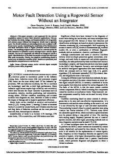
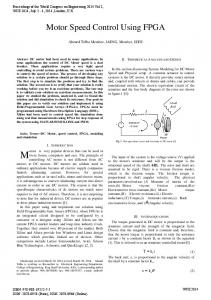
A three-phase cage motor is considered, its rotor is constituted of nb isolated bars, distributed uniformly on the surface of the rotor and shortcircuited by two rings. In order to study its performance, we used a model where the cage is considered like a mesh circuit as shown in Fig. 1. The number of differential equations obtained is equal to the number of bars plus one (so as to take into account one of the two rings) [6].
The frequencies of the characteristic harmonics of the different faults (or CHF) are found to be intimately tied to the slip and hence to the rotor speed [4, 5]. The knowledge of the rotor speed of the machine is therefore essential for the calculation of the CHF frequencies and facilitates their detection in the SCS spectrum.
Fig. 1 The mesh circuit of the cage rotor.
Under classical hypotheses, the mathematical model of the machine is given by equations of the voltage [7, 8]:
[V ] = ⎡⎢ R + dL ⎤⎥[I ] + [L] d [I ] ⎣
d dt
dt ⎦
dt
[I ] = −[L]−1 ⎡⎢ R + dL ⎤⎥[I ] + [L]−1[V ] ⎣
dt ⎦
(1)
(2)
ISSN 1335-8243 © 2007 Faculty of Electrical Engineering and Informatics, Technical University of Košice, Slovak Republic
2
Cage Motor Faults Detection Algorithm Using Speed Estimation and Current Analysis
⎡ n ⎤ f hpr1 = f1 ⎢ b (1 − s ) − 1⎥ ⎣ p ⎦
3. SCS SPECTRUM CONTENT WITH AND WITHOUT FAULTS 3.1. Machine without fault Under normal operating conditions of a healthy induction machine, besides the fundamental harmonic, appears in the SCS spectrum, the HPER frequency, fher given by the following expression [9]: ⎡kn ⎤ (3) f her = f1 ⎢ b (1 − s ) ± ν ⎥ ⎢⎣ p ⎥⎦ where f1 is the fundamental supply frequency, s is the slip, p is the number of pole pairs, v is the stator time harmonics order that are present in the supply voltage, nb is the rotor bars number and k is any positive integer number. The harmonics created by taking into account the effect of the space harmonics components have the same frequencies as those due to the slotting effect [10]. 3.2. Machine with broken bars fault Under abnormal operating conditions related to the asymmetry caused by the broken rotor bars fault, sequence of additional sidebands components appear around the fundamental at frequency f b given by [6, 9]: f b = ( 1 ± 2ks)f1
(4)
These classical twice slip frequency sidebands components are the characteristic harmonics (CHF) that have been widely used in scientific literature to diagnose broken bars fault. Other spectral components can appear in the SCS spectrum at frequencies given by the expression [4, 9]: ⎡ k ⎤ fb = ⎢ (1 − s ) ± s ⎥ f1 (5) ⎣⎢ p / 2 ⎦⎥ where
k p/2
= 1, 3, 5, 7, 9, 11,....
4. THE PROPOSED ALGORITHM DESCRIPTION The algorithm is being designed for the diagnosis of faults in electrical machines. The diagnosis is based essentially on the localization of the CHF which are directly linked to the slip of the machine. It is the reason for which any procedure elaborated for the localization of the CHF will have as a first task to estimate the slip (i.e. the speed) of the machine. For the speed estimation, we consider only the HPR1 frequency f hpr1 given by:
(6)
from this equation one can deduce the rotor speed as follows:
n=
60 ( fhpr1 + f1 ) nb
(7)
We notice in Equation (7) that the speed estimation requires the knowledge of the supply frequency f1 , the number of rotor cage bars nb and the frequency f hpr1 of the HPR1. The search is done within an interval bounded by two frequencies, the higher frequency corresponding to a no-load operation (s=0) and the lower frequency corresponding to an overload operation (slip of the order s=0.07). This interval is selected in order to correspond to all the cases of possible working of the machine. It is important to note that in this interval the amplitude of the HPR1 is the most important [5]. Therefore, once the interval is delimited, a scanning is done in order to find the frequency of the harmonic of maximal amplitude which will then correspond to the HPR1 frequency. The proposed algorithm for speed estimation and faults detection can be summarized by the following steps: 1. Data acquisition of stator current signal (SCS). 2. Determination and analysis of the SCS spectrum (FFT). 3. Localization of the HPR1 in the SCS spectrum. This is done by scanning the interval [( nb /p-2)f1, ( nb /p-1)f1]
containing
the f hpr1 obtained
from
Equation (6), in order to determine the harmonic having the largest amplitude. 4. Estimation of the speed from Equation (7). 5. Prediction of the CHF frequencies using Equation (4). The prediction of these frequencies means that if a fault exists, the harmonic frequencies of that fault on the SCS spectrum must correspond inevitably to the predicted frequencies. 6. Scanning of the SCS spectrum with the purpose to know if the harmonics having these frequencies do exist, so as to conclude on the presence or absence of faults linked to these harmonics. 7. Assessment of the degree of fault severity. This is done by the comparison of the amplitude of the CHF with those contained in the data base. This data base contains the interval of variation of the characteristic amplitudes of the different CHF faults for different degrees of severity.
ISSN 1335-8243 © 2007 Faculty of Electrical Engineering and Informatics, Technical University of Košice, Slovak Republic
Acta Electrotechnica et Informatica No. 2, Vol. 7, 2007
5. SIMULATION RESULTS AND INTERPRETATIONS A simulation program written in C++ is developed in order to highlight the algorithm performance for faults detection. The induction motor used is a 7.5 HP, 4 poles, 50Hz, 220/380volts, 36 stator slots and 28 rotor bars. A stator current spectral analysis using the FFT of the Matlab is carried out on both a healthy motor and a faulty one. The faults dealt with are broken bars fault but the algorithm can also be extended to include eccentricity faults as shown in Fig. 6. The presence of these faults is generally illustrated by the appearance of characteristic harmonic frequencies CHF in the SCS spectrum. Since the prediction of these frequencies is being based on the calculation of the speed, the error made in the speed calculation will be reflected on the calculation of these frequencies. Due to this fact, the search for frequencies of the CHF is carried within an interval of f ± ∆f, with ∆f being the resolution of the fast Fourier transform (FFT).
3
(or slip) enables one to predict the frequencies of the CHF using Equation (4). The broken bars fault frequencies are then predicted as fb1 = 47.43 Hz and fb2 = 52.57 Hz.
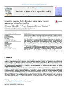
5.1. Algorithm application for speed estimation In this first case we present two applications of the algorithm for speed calculation by using the localization of the HPR1 for both a healthy and then a faulty motor. Figure 2, depicts the speed waveform and the SCS spectrum respectively at the neighborhood of the interval of search for the HPR1 in the case of a healthy motor. The application of the algorithm for speed calculation in the SCS spectrum of Fig. 2.b, gives the frequency of the HPR1, f hpr1 = 643.2 Hz.
Fig. 2 (a) Rotor speed (b) SCS spectrum, for a healthy motor.
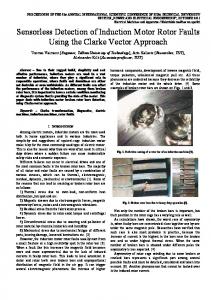
From Equation (7) the speed is therefore calculated as ncalc = 1485.42 rpm. Comparing this calculated speed to that shown in the motor speed curve of Fig. 2.a, where n = 1485.09 rpm, one can deduce that there are almost equal. Figure 3, shows also the speed waveform and the SCS spectrum respectively but for the case of a three broken bars faulty motor. The frequency of the HPR1 in Fig. 3.b, is f hpr1 = 637.6 Hz. From Equation (7) ncalc = 1473.4 rpm, which is again equals to that shown in the motor speed curve of Fig. 3.a, where n = 1473.3 rpm. 5.2 Algorithm application for faults detection In this second case we present three applications of the algorithm for faults detection for both a healthy and then a faulty motor. Figure 4, Figure 5 and Figure 6, illustrate respectively zooms of a portion of the SCS spectrum around (a) the HPR1, (b) the fundamental and (c) the HPER. The execution of the algorithm for fault detection on the SCS spectrum shown by Fig. 4.a, gives a frequency f hpr1 = 632 Hz. From Equation (7) the calculated speed ncalc = 1461.42 rpm. This speed
Fig. 3 (a) Rotor speed (b) SCS spectrum, for a three broken bars fault motor.
ISSN 1335-8243 © 2007 Faculty of Electrical Engineering and Informatics, Technical University of Košice, Slovak Republic
4
Cage Motor Faults Detection Algorithm Using Speed Estimation and Current Analysis
A scanning of the SCS spectrum around the fundamental component Fig. 4.b, and the rotor slots harmonics Fig. 4.c, respectively shows that the harmonics of the predicted frequencies fb1 and fb2 do not exist; therefore one can conclude that this application is concerned with a healthy motor.
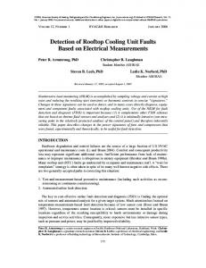
Fig. 5 Zooms of the SCS spectrum respectively for (a) the HPR1, (b) the fundamental, (c) the HPER for a broken bars fault motor.
Fig. 4 Zooms of the SCS spectrum respectively for (a) the HPR1, (b) the fundamental, (c) the HPER for a healthy motor. The execution of the algorithm for fault detection on the SCS spectrum shown by Fig. 5.a, gives a frequency f hpr1 = 630 Hz. From Equation (7) the calculated speed ncalc = 1457.14 rpm. This speed (or slip) enables one to predict frequencies of the CHF using Equation (4). The broken bars fault frequencies are then predicted as fb1 = 47.14 Hz and fb2 = 52.85 Hz. A scanning of the SCS spectrum around the fundamental component Fig. 5.b, and the rotor slots harmonics Fig. 5.c, respectively, enables us to detect the existence of the harmonics of the broken bars fault at frequencies fb1 = 47.2 Hz and fb2 = 52.8 Hz which are very close to those predicted, and therefore confirms the existence of the broken bars fault.
A last execution of the algorithm for fault detection on the SCS spectrum is given by Fig. 6. This concerns the case of the simultaneous presence of both broken bars and mixed eccentricity faults. The frequency of the HPR1 and the calculated speed have the respective values of fhpr1= 638.4 Hz and ncalc = 1475.14 rpm. The predicted frequencies of the CHF using Equation (4) are obtained as fb1 = 48.34 Hz and fb2 = 51.65 Hz for broken bars fault. The dynamic eccentricity fault frequencies fd1 = 589.23Hz and fd2 = 687.57 Hz and the mixed eccentricity fault frequencies fm1= 25.41 Hz and fm2 = 74.58 Hz are obtained using eccentricity equations found in [11, 12, 13]. A scanning of the SCS spectrum around the fundamental component Fig. 6.b, and the rotor slots harmonics Fig. 6.c, enables one to detect the existence of the harmonic frequencies predicted above for both the broken bars fault and the eccentricity faults. This confirms and proves the existence of the harmonics linked to the two types of fault.
ISSN 1335-8243 © 2007 Faculty of Electrical Engineering and Informatics, Technical University of Košice, Slovak Republic
Acta Electrotechnica et Informatica No. 2, Vol. 7, 2007
5
paper dealt with broken bars faults diagnosis, the algorithm is capable to incorporate other types of faults such as eccentricity faults. REFERENCES [1] Kliman, G.B, Stein, J : Method of current signature analysis, Electric Machines and Power Systems, No. 20, pp. 463-474. [2] Nandi, S, Toliyat, H.A : Fault diagnosis of electrical machines-A review, IEEE-IEMDC, 1999, pp. 219-221. [3] Ferrah, Bradley A K. J, Asher, G. M : Sensorless speed detection of inverter fed induction motors using rotor slot harmonics and fast Fourier transform, IEEE Power Electronics Specialist Conf., June 29 July 3, 1992. [4] Deleroi, W : Broken bar in squirrel cage rotor of an induction motor, Part1: Description by superimposed fault currents, Archiv für Elektrotechnik, volume 67, 1984, pp. 91-99. [5] Toumi, D : Détection des défauts rotoriques dans la machine asynchrone (cassure des barres etexcentricité), Thèse de magister, Université des Sciences et de la Technologie d’Oran, 2002. [6] Fillipetti, F, Franceschini, G, Tassoni, Vas, P: Impact of speed ripple on rotor fault diagnosis of induction machines, ICEM'96, volume 2, 1996, pp. 452-457.
Fig. 6 Zooms of the SCS spectrum respectively for (a) the HPR1, (b) the fundamental, (c) the HPER of a mixed eccentricity and bars fault motor.
6. CONCLUSION In this paper a proposed algorithm for the detection and localization of broken bars faults of a squirrel cage induction motor is being developed and described. This algorithm has for first task the estimation of the rotor speed using the frequency of the first principle rotor slots harmonics (HPR1), then the prediction of the frequencies of the characteristic harmonics of faults (CHF) and finally the search in the SCS spectrum for the existence or absence of harmonics at the predicted frequencies. In order to simulate both the healthy and faulty motors behavior, a mathematical model is being adopted and a simulation program using C++ is being developed. The obtained simulation results have been shown to illustrate the good performance, the utility and merits of the proposed algorithm both for speed estimation and faults detection and localization in induction machines. Although this
[7] Bennouzza, N, Benyettou, A, Bendiabdellah, A : An Advanced park’s vector approach f or rotor cage diagnosis, IEEE Control. Communications and Signal Processing. 2004, pp. 461-464. [8] Drif, M, Bendiabdellah, A, Bennouzza, N, Dente, J.A: Induction motor load effect diagnostic utilizing instantaneous power spectrum, EPE Power Electronics and Application, 2001, pp. 27-29. [9] Vas, P: Parameter evaluation, condition monitoring and diagnosis of electrical machines, Clarendron Press, Oxford, 1993. [10] Shalaby, M : Effect of air-gap fluctuations on the performance of the squirrel cage induction motor, Archiv für Elektrotechnik, volume 60, 1978, pp. 143-150. [11] Dorreli, D.G, Thomson, W.T, Roach, S: Analysis of air-gap flux, current, vibration signals as a function of the combination of static and air-gap dynamic eccentricity in 3 phase induction motors, IEEE Trans. Ind. Appl., volume 33, No.1, 1997, pp. 24-34. [12] Nandi, S, Bharadwaj, R.M, Toliyat, H.A,,Parlos, AG : Performance analysis of a three phase induction motor under
ISSN 1335-8243 © 2007 Faculty of Electrical Engineering and Informatics, Technical University of Košice, Slovak Republic
6
Cage Motor Faults Detection Algorithm Using Speed Estimation and Current Analysis
incipient mixed eccentricity condition, IEEE, PEDES Conference Proceedings, Nov 30Dec.3, 1998. [13] Thomson, W.T, Rankin, D, Dorrell, D.G : On-line current monitoring air-gap eccentricity in large three–phase induction motors– Industrial case histories verify the predictions, IEEE Transaction on Energy Conversion, volume 14, no. 4, 1999.
BIOGRAPHIES Azeddine Bendiabdellah was born on January, 10, 1958 in Saida Algeria. He received his Bachelor Engineering degree with honors from the University of Sheffield, England, in 1980, and the Ph.D degree from Sheffield University in 1985, where he worked on electrical machines design under Professor Mc. McCormick. From 1990 to 1991 he was a visiting professor at Tokyo Institute of Technology (T.I.T), Japan, where he worked on electrical machines control under Professor T. Kataoka. He is currently Professor of Electrical Engineering at the University of Sciences and Technology of Oran, Algeria. His research interests include Electrical machines
Design and Drives Control and Converters; Numerical Methods for Field Calculations, as well as Electrical machines Faults Diagnosis. Noureddine Benouzza was born on August, 17, 1963 in Oran Algeria. He received his B.S degree in Electrical Engineering from the University of Sciences and Technology of Oran, Algeria, in 1989, and the M.S degree from the same University of Sciences and Technology of Oran, in 1993. He is currently Professor of Electrical Engineering at the University of Sciences and Technology of Oran. His research interests include Electrical machines and Drives Control, Power Electronics, as well as Electrical machines Faults Diagnosis. Djillali Toumi was born was on August, 20, 1971 in Tiaret Algeria. He received his B.S degree in Electrical Engineering from the University of Tiaret, Algeria, in 1995, and the M.S degree from the University of Sciences and Technology of Oran, in 2002. He is currently a lecturer of Electrical Engineering at the University of Tiaret, Algeria. His research interests include Electrical machines, Power Electronics, as well as Electrical machines Faults Diagnosis.
ISSN 1335-8243 © 2007 Faculty of Electrical Engineering and Informatics, Technical University of Košice, Slovak Republic