Melbourne Institute of Technology (RMIT) University .... makes use of automotive grade MEMS inertial sensors ... vehicle 180 degrees in the same location.
Calibrated MEMS inertial sensors with GPS for a precise attitude heading reference system on autonomous farming tractors Yong Li1, Damien Dusha2, William Kellar2, Andrew Dempster1 1 University of New South Wales, Sydney, NSW2052, Australia 2 Leica Geosystems, Brisbane, QLD 4102, Australia
BIOGRAPHY Yong Li is a Senior Research Fellow at the School of Surveying & Spatial Information Systems, the University of New South Wales (UNSW), Sydney, Australia. He obtained a PhD in flight dynamics in 1997. He worked at the Beijing Institute of Control Engineering for GPS aerospace applications from 1997 to 2000. From 2000 to 2002 he was a STA Fellow at the Japanese Aerospace Exploration Agency (JAXA, formerly the National Aerospace Laboratory of Japan). Prior to join UNSW, he has worked on the GPS sports application at Royal Melbourne Institute of Technology (RMIT) University under the Cooperative Research Centre for Micro Technology from 2002 to 2004. His current research interests include multisensor integration of GPS, INS, and pseudolites (Locata), attitude determination, GPS receiver technologies, and optimal estimation/filtering theory and applications. Damien Dusha is a Software Engineer with Leica Geosystems in Brisbane, Australia where he works on GPS systems with applications in agriculture, mining and construction. He is currently undertaking a PhD with the Queensland University of Technology, Brisbane. William Kellar is a Navigation Systems Engineer with Leica Geosystems in Brisbane, Australia. In 2002 he obtained dual bachelors degrees in Information Technology and Electronic Engineering from the Queensland University. From 2002 to 2006 he conducted research at the Cooperative Research Centre for Satellite Systems (CRCSS), where he worked on ground support software for the GPS payload of the FedSat spacecraft and developed data compression techniques for real-time kinematic GPS reference networks. Andrew Dempster is Director of Research in the School of Surveying and Spatial Information Systems at the University of New South Wales. He has a BE and
MEngSc from UNSW and a PhD from University of Cambridge. He was system engineer and project manager for the first GPS receiver developed in Australia in the late 80s and has been involved in satellite navigation ever since. His current research interests are in satellite navigation receiver design and signal processing, and new location technologies. ABSTRACT GNSS/INS (Global Navigation Satellite System/Inertial Navigation System) systems have found widespread usage in industry and especially in automated agriculture. These systems produce a high frequency attitude solution for mobile agents. The mojoRTK, an agricultural product from Leica Geosystems, is based around a GPS/INS system, utilizing a survey-grade L1/L2 GPS/GLONASS antenna in addition to another L1 GPS antenna. A new algorithm based on loose GNSS/INS integration has been developed in the University of New South Wales for mojoRTK system which is known as AHRSKF (Attitude and Heading Reference System Kalman Filter).The advantage of the AhrsKf is that it takes inputs from the survey grade L1/L2 antenna alone, thus reducing or eliminating the need for the two antenna system used in the existing mojoRTK algorithm. The initial analysis has shown that the two (AhrsKf and existing mojoRTK) solutions have comparable performance. This paper introduces the integration Kalman filter design and addresses its implementation aspects. Multiple L1/L2 GPS receivers in a three antenna configuration are set up in the test as a benchmark to evaluate the AhrsKf solution. The test was conducted at the Leica Geosystems testing farm at Boonah in a tractor equipped with a mojoRTK autosteer system. The AhrsKf solution is derived in a post-processing procedure by using the recorded L1/L2 GNSS and inertial sensor data from the log files of the mojoRTK console. The performance of the algorithms is compared by extracting the time series of
the errors in yaw, pitch and roll solutions relative to the reference multi-antenna GPS solution. INTRODUCTION As global climate change and energy cost rises become increasingly challenging, efficient use of limited resources is becoming a more and more critical issue to social life and economy. Application of state-of-the-art navigation technology to precision agriculture can improve the efficiency of resource usage in farming. This may include increased yield from crops, reduced input costs due to overlap, reduced driver fatigue, reduced fuel usage and reduced water usage in irrigation. In the next decade, machine automation will play an important role in an agriculture revolution. Already the impact of automating processes such as ploughing, planting and application of fertilizers is being felt in many types of farming. Tractors in precision farming are usually operated in an environment where the terrain is rarely smooth and flat, and speed is relatively low. Fast vibrations on the horizontal axes can be observed over uneven terrain and thus an attitude solution with a fast update rate is necessary for such vehicle guidance. A multiple-antenna GPS can be used to determine the host platform’s orientation, of which the attitude accuracy mainly depends on the noise level of the carrier phase measurements and the baseline length separated by the antennas[1][2]. The drawback of the GPS-only attitude determination system is that the cost of the system increases quickly as the updating rate increases [3]. Future digitized autonomous farm management systems need to be capable of smartly planning the farming process according to the growth status of the plants. Therefore the precise position is also important in the precise farming. With a local reference station the current relative kinematic (RTK) GPS can achieve centimeter level accuracy. When Networked RTK infrastructure is available, the local reference station is no longer needed.
misalignment, scale factor biases and temperature drift, an inertial solution alone cannot rely on its accuracy for even a short period of time. Well calibrated and smart filtering can help to address this problem to achieve a low-cost, precise, and high update rate attitude determination system [5]. For example, the Leica mojoRTK system makes use of automotive grade MEMS inertial sensors and a dual frequency survey grade GPS/GLONASS receiver to provide position and attitude information that is suitable for agricultural guidance and machine control applications [6]. In collaboration with Leica Geosystems, the University of New South Wales (UNSW) is developing an optimal fusion algorithm for the mojoRTK. This paper introduces the drivers of the development. To achieve higher accuracy, the MEMS inertial sensors are characterized at different operation temperatures. The relationship between the sensor bias and the operating temperature is modeled. The verified model is further used to calibrate the inertial outputs, which are compensated further onthe-fly by the error estimates from the integration Kalman filter using the GPS data. In addition to position and/or velocity used as the measurements, two specified designs are addressed in our development: (1) the GPS derived heading (when moving) and the accelerometer derived pitch and roll (when static) are augmented in the measurements in our designed integration filter. This design can improve the heading’s observability of the system; (2) pre-filtering the raw MEMS inertial data and temperature compensation. In the test, an agricultural tractor with the mojoRTK was operating on a low-value row crop. A key indicator in row cropped agricultural applications is to minimize the crosstrack error of the tractor. In the field test, four GPS antennas, which were used to determine accurate roll, pitch and heading, were amounted on the roof of the tractor as a benchmark.
Taking into account demands on the precise position and attitude as well as high update rate, an ideal navigation system for precision farming could look like, (1) to keep the existing GPS system if possible, to provide a precise position; (2) to use external sensors to improve the update rate and availability; (3) to use the external sensors (possibly including an additional GPS) for sensing attitude; (4) to keep the system as cheap as possible. The combination of Micro-Electro-Mechanical inertial sensors (MEMS) with GPS can potentially satisfy all the above requirements for ideal navigation [4]. Since lowcost MEMS sensors are much less accurate than their optical counterparts due to their sensor biases, axis
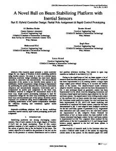
Fig. 1 Leica’s autonomous farming tractor
Both GPS and inertial data were collected at 10Hz and stored in a USB flash drive in the tests. The attitude solution from the current algorithm of mojoRTK was also recorded and used for comparison with our integrated solution. The results show that the integration system provides a good position and attitude solution with an acceptable error range. This demonstrates that this MEMS-IMU/RTK integrated system has the capability of providing continuous and reliable navigation for machine automation applications. CALIBRATION OF THE MEMS SESORS The mojoRTK sensors consist of three rate gyros, a three axis accelerometer, and a 2-axis magnetometer. In addition to these sensors, the system includes two GPS receivers – a dual frequency L1/L2 GPS/GLONASS receive and a low-cost L1-only single frequency GPS receiver, that produce a two axis attitude solution which is used for estimating the biases of the inertial sensors. The inertial and GPS data are processed by an embedded 400MHz PowerPC processor, as illustrated in Fig.2, a photo of the mojoRTK is shown in Fig. 3. The specifications of the MEMS gyros in mojoRTK are listed in Table 1:
The development in MEMS technology has made it possible to fabricate low-cost single chip accelerometer and gyro sensors, which have been adopted into many applications where inertial sensors have traditionally been too costly. The obtained accuracy and convergence time of a GNSS-aided INS is highly dependent on the quality of the IMU sensors output, and therefore a calibration of the IMU is critical for the overall system performance [8]. The calibration of the mojoRTK system is conducted by performing two maneuvers with the vehicle [3]. The first maneuver involves sitting the vehicle in a stationary position for a short period of time, then rotating the vehicle 180 degrees in the same location. This allows the system to estimate the roll and pitch orientation of the mojoRTK console within the vehicle reference frame, and estimate the bias of the accelerometers. The yaw orientation is manually entered by the operator and is usually zero or +/-90 degrees, depending on the location of the radio slot in the tractor. The second maneuver compensates for the hard iron effects on the magnetometer. Because the magnetometer is not used in the integration Kalman filter, the second maneuver is not needed for the AhrsKf. The temperature-compensated inertial data are fed into the integration Kalman filter. With aided by the GPS, the residuals of the inertial sensor errors are further estimated and corrected in the Kalman filtering. INTEGRATION OF GPS AND INS
Fig. 2 The hardware configuration of the mojoRTK [3]
The Leica mojoRTK system makes use of automotive grade MEMS inertial sensors and a dual frequency survey grade GPS/GLONASS receiver to provide position and attitude information that is suitable for agricultural guidance and machine control applications. The GPS/INS integrated algorithm consists mostly of two parts as depicted in Fig. 4: • Initial alignment • Integrated navigation
Fig. 3 Photo of mojoRTK [6] Table 1 Technical specifications of MEMS gyros [7]
Fig. 4 Procedure of the AhrKf algorithm
Software for Leica mojoRTK is being developing for both real-time and post-processing the GPS and INS data for attitude estimation of mojoRTK. Initial alignment The MEMS gyros in the mojoRTK have insufficient resolution and accuracy to measure the Earth’s rotation rate and therefore only the coarse alignment algorithm listed below is applied. When the vehicle is static or at constant velocity,, according to Newton’s seconds law, the accelerometer measurements will satisfy f +g =0
(1)
The pitch and roll can be computed from the accelerometer output during the stationary period as below, ⎛ fx ⎝ g
θ = sin −1 ⎜⎜
⎞ ⎟⎟ ⎠
(2)
⎛ fy ⎞ γ = tan −1 ⎜⎜ ⎟⎟ ⎝ fz ⎠
(3)
When the mojoRTK is configured as two-antenna GPS system, the heading derived from the GPS can be used in the alignment.
Integrated navigation
(
(4)
)
n v& n = − 2ω ien + ω en × vn + f n + gn
q& =
1 Q(ω bnb )q 2
(5) (6)
where the 4 by 4 matrix Q is [10]: ⎡ 0 ⎢− ω Q(ω bnb ) = ⎢ 1 ⎢− ω 2 ⎢ ⎣ − ω3
The INS error equations are expressed in the n-frame. Through vector perturbation analysis on the navigation equations (4) to (6), one can derive the navigation error equations (e.g. by referring to [11]): The tri-axial attitude error equations: φ&E = ( Ω sin L + V E /( R n + h ) tgL )φ N − ( Ω cos L + V E /( R n + h ))φ u (8) − δ V N /( R m + h ) + V N /( R m + h ) 2 δ h + ε E
φ&N = − ( Ω sin L + V E /( R n + h ) tgL )φ E − V N ( R m + h )φ U + δ V E /( R n + h )
(9)
− Ω sin L δ L − V E /( R n + h ) δ h + ε N 2
φ&U = ( Ω cos L + V E /( R n + h )) φ E + V N /( R m + h )φ N + δ V E /( R n + h ) + ( Ω cos L + V E /( R n + h ) sec
2
(10)
L )δ L
− V E tgL /( R n + h ) 2 δ h + ε U
The tri-axial velocity error equations:
Strapdown INS navigation computation equations can be written in either navigation coordinate system (n-frame) [9] or earth-centre-earth-fixed coordinate system (eframe). The INS error equations correspondently can be written in either one of the frames. The strapdown inertial navigation mechanism is implemented in the navigation frame for position-, velocity-, and attitude- updating, respectively below, n r& n = v n − ω en × rn
The attitude-updates are implemented through the quaternion approach. The strapdown mechanism derives the navigation solution through integration of the acceleration and the angular velocity sensed by the accelerometer and the gyros, the errors of these inertial sensors cause drift of the navigation solution with time. The drift rate heavily depends on the accuracy of the inertial sensors. To resolve this problem to obtain a longterm stable navigation solution, external aiding such as GPS is necessary to estimate the navigation and sensor errors.
ω1
δV&E = − fU φ N + f N φU + δV E (V n tgL − VU ) /( R n + h ) + ( 2 Ω sin L + V E tgL /( R n + h ))δ V N − ( 2 Ω cos L + V E /( R n + h ))δ VU
(11)
+ ( 2 ( Ω cos LV N − Ω sin LVU ) + V EV N sec 2 L /( R n + h ))δ L + ((V EVU − V N V E tgL ) /( R n + h ) 2 )δ h + ∇ E
δV&N = fU φ e − f eφU − 2 (Ω sin L + V E tgL /( Rn + h ))δV E − (VU δV N + V N δVU ) /( Rm + h )
(12)
− ( 2 Ω V E cos L + V E2 sec 2 L /( Rn + h ))δL + (V N VU /( Rm + h ) 2 + V E2 tgL /( Rn + h ) 2 )δh + ∇ N
δ V&U = − f N φ E + f E φ U + 2V N /( R m + h )δ V N + 2 ( Ω cos L + V E /( R n + h )) δ V E − 2 Ω sin LV E δ L + (2 g / R − V
2 E
/( R n + h ) − V 2
2 N
(13)
/( R m + h ) ) δ h + ∇ U 2
The position error equations in latitude, longitude, and height are as below,
0
ω2 ω3
− ω3
0
ω2
− ω1
ω3 ⎤ − ω 2 ⎥⎥ ω1 ⎥ ⎥ 0 ⎦
(7)
δL& = δVN /( Rm + h) − VN /( Rm + h) 2 δh (14) & δλ = sec L /( Rn + h)(δVE + VE tgLδL − VE /( Rn + h)δh) (15) δh& = δVU (16)
The GPS position and velocity are used to derive the position and velocity errors of the INS. By setting the state vector X = [φ E , φ N , φU , δVE , δVN , δVU , δL, δλ, δh, ε x , ε y , ε z , ∇ x , ∇ y , ∇ z ]T
(17)
The final 6 states are sensor error terms, which are modelled as random-walk in the AhrsKf. The measurement equations for velocity and position are ⎡ v IE − vGE ⎤ Z v (t ) = ⎢⎢ v IN − vGN ⎥⎥ = H v X(t ) + Vv (t ) ⎢⎣v IU − vGU ⎥⎦ ⎡ LIE − LGE ⎤ Z p (t ) = ⎢⎢λ IN − λGN ⎥⎥ = H p X(t ) + V p (t ) ⎢⎣ hIU − hGU ⎥⎦
Generally, two nonparallel vectors can uniquely determine a Cartesian coordinate system. If there are two nonparallel vectors u and v,the unit vectors along three axes of the coordinate system which are represented as i, j, and k,can be calculated from u and v as below,
(18)
(19)
When the speed of the vehicle is fast enough, e.g. 3m/s, the GPS velocity can be used to derived the heading of the movement at an accuracy of about 0.57deg (assuming the GPS velocity error at 3cm/s). The heading derived from the GPS velocity then can be used to correct the INS heading in the integration Kalman filter:
Zψ (t ) = ψ INS − ψ G = φu + VM
In contrast to the normal TRIAD algorithm which is sensitive to the master vector, the improved TRIAD algorithm is applied here, which has the advantage of being insensitive to the master vector [12].
GPS ATTITUDE SOLUTION
Three GPS/GLONASS L1/L2 receivers are used to derive the benchmark attitude solution to evaluate the AhrsKf solution. Two baselines are separated by the three GPS antennas. The coordinates of the baselines in the vehicle’s body frame can be manually measured and thus are known. The coordinates of the baselines in the navigation frame can be derived from the double-differenced carrier phase measurements. Once these two kinds of coordinates are known, following algorithm can be applied to derive the tri-axial attitude solution of the vehicle. The accuracy of the solution is determined by the accuracy of the double-differenced carrier phase measurements and the length of the baselines. The longer the baselines, the higher accuracy the attitude solution [1].
j = i × (u − v ) i × (u − v)
(21)
k = i× j
(22)
coordinates in R-frame and B-frame are v R and v B , respectively. The unit vectors of axes of R-frame can be calculated from u R and v R by using Eqs. (20) to (22). Similarly, the unit vectors of axes of B-frame can be calculated from u B and v B by using Eqs. (20) to (22) too. The transformation matrix from R-frame to B-frame can be obtained as below,
(20)
(21)
(20)
Assuming u’s coordinates in the reference coordinate system (R-frame) and the body frame system (B-frame) are i.e., u R and u B , respectively. Similarly, v’s
So the equation of measurement is written in a matrix form as below ⎡Zv ⎤ ⎡03×2 03×1 I3×3 03×3 03×3 03×3 ⎤ ⎢ ⎥ Z = ⎢Z p ⎥ = ⎢⎢03×2 03×1 03×3 I3×3 03×3 03×3 ⎥⎥X + V ⎢Zψ ⎥ ⎢⎣01×2 1 01×3 01×3 01×3 01×3 ⎥⎦ ⎣ ⎦
i = (u + v) u + v
A = M B M TR
(23)
M B = [i B j B k B ]
(24)
M R = [i R j R k R ]
(25)
TESTS The test was conducted at Boonah, near Brisbane on 13 May 2009. In the test multiple GPS receivers and the mojoRTK were mounted on the tractor. The data from multiple GPS are used to derive the attitude solution as the reference to evaluate the AhrsKf solution. The installation of the GPS antennas is illustrated in Fig. 5. The longest baseline has a 3m long, from which the heading and roll can be derived at an accuracy of 0.056deg (3mm/3m=0.056deg by assuming 3mm accuracy of the double-differenced carrier phase measurements). The forward component of the baselines is 700mm, the derived pitch has an accuracy of 0.25deg (=3mm/700mm). Thus, the GPS-derived attitude is accurate to evaluate the AhrsKf solution.
090513: vx,vy,vz 5 4 3 2
v (m/s)
1 0 -1 -2 -3 -4 -5 1.2422 1.2422 1.2422 1.2422 1.2422 1.2422 1.2422 1.2422 1.2422 1.2422 9 time(s) x 10
Fig. 5 Installation of the GPS antennas in the test
Fig.7 Velocity solution
AhrsKf solution
090513: Roll 6
4
2
roll (deg)
The AhrsKf processes the data from the right-hand side GPS antenna and the inertial data. The position and velocity solution of the AhrsKf are depicted in Figs 6 and 7. The roll, pitch and heading are depicted in Figs 8 – 10, respectively. The tractor was driven at a speed of 2-5m/s on the straight lines, and around 2m/s at turns. The operation field is relatively flat, both the roll and pitch are within ±2deg (1 σ ). The heading changes in turns are coincided with the direction changes of the velocity as depicted in Figs. 7 and 10. From Figs. 6-10, it is easy to find that the AhrsKf solution stably and correctly tracks the movement.
0
-2
-4
-6
-8 1.2422 1.2422 1.2422 1.2422 1.2422 1.2422 1.2422 1.2422 1.2422 1.2422 9 time(s) x 10
Fig.8 Roll – time curve 090513: Pitch 6
4
pitch (deg)
2
0
-2
-4
-6
-8 1.2422 1.2422 1.2422 1.2422 1.2422 1.2422 1.2422 1.2422 1.2422 1.2422 9 time(s) x 10
Fig.9 Pitch – time curve Fig.6 Ground trajectory on Google Earth
090513: Heading 400
400
350
350 300 h e a d in g (d e g )
300
heading (deg)
data1 data2
250 200
250 200 150
150
100 100
50
50
0 1.2422
1.2422
0 1.2422 1.2422 1.2422 1.2422 1.2422 1.2422 1.2422 1.2422 1.2422 1.2422 9 time(s) x 10
1.2422
1.2422
1.2422
1.2422 9
x 10
The epoch-by-epoch difference of the AhrsKf and GPS attitude solutions is depicted in Fig. 12, and the statistic result of the difference is listed in Table 2. Roll 6 5 4 3 2 ro ll (d e g )
The AhrsKf attitude solution is particularly interested. The AkrsKf and multi-antenna GPS attitude solutions are depicted in Fig. 11 below, where the AhrsKf solution is plotted in the red line, and the GPS solution in blue. It can be found that the AhrsKf solution is coincided with the GPS solution to correctly track the changes of all the attitude angles in the movement. It can also be found that the AhrsKf solution is noisy than the GPS solutions. 8 data1 data2
1 0 -1
4
-2
2 ro ll (d e g )
1.2422 1.2422 time(s)
Fig.11 AhrsKf and GPS attitude solutions
Comparison of AhrsKf and GPS attitude solutions
-3 -4 1.2422
0
1.2422
1.2422
-2
1.2422
1.2422 time(s)
1.2422
1.2422
1.2422
1.2422 9
x 10
(a) Roll difference
-4
Pitch 8
-6
6
1.2422
1.2422
1.2422
1.2422 1.2422 time(s)
1.2422
1.2422
1.2422
4
1.2422 9
x 10
p it c h (d e g )
-8 1.2422
1.2422
(c) Heading solutions
Fig.10 Heading – time curve
6
1.2422
(a) Roll solutions
2
0
8 -2
data1 data2
6
-4
p it c h (d e g )
4 -6 1.2422
2
1.2422
1.2422
1.2422
1.2422 time(s)
1.2422
1.2422
1.2422
1.2422 9
x 10
(b) Pitch difference
0
Heading
-2
15
-4 10
-8 1.2422
1.2422
1.2422
1.2422
1.2422 1.2422 time(s)
(b) Pitch solutions
1.2422
1.2422
1.2422
1.2422 9
x 10
h e a d in g (d e g )
-6 5
0
-5
-10 1.2422
1.2422
1.2422
1.2422
1.2422 time(s)
1.2422
1.2422
1.2422
1.2422 9
x 10
(c) Heading difference
Fig. 12 The difference of the Ahrskf and GPS attitude solutions
Table 2 statistic result of the difference between AhrsKf and GPS attitude solutions
Min (deg) Max (deg) Ave (deg) Std (deg)
Roll ‐3.62 5.90 ‐0.11 0.80
pitch ‐5.72 6.43 ‐0.11 1.39
heading ‐8.46 12.01 ‐0.40 1.43
From Table 2, the stand deviations of the angle differences are 0.80deg on roll, 1.39deg on pitch, and 1.43deg on heading. The overall stand deviation of three axes is 2.15deg. The absolute average differences are 0.11deg on roll and pitch, and 0.4deg on heading, which means that the AhrsKf solution is well coincided with the GPS solution.
CONCLUDING REMARKS The AhrsKf for the mojoRTK has been successfully developed to fuse MEMS inertial data with GPS data to generate an attitude solution for an autonomous agricultural tractor. The MEMS inertial sensors are temperature compensated in the initialization phase of the operation, with the estimation of sensor biases continually updated by the AhrsKf in the succeeding operation to ensure a long-term stable solution. The test results have demonstrated that the AhrsKf solution is stable and can correctly track the movement of the tractor In comparison with the GPS solution, the AhrsKf solution is well coincided with the GPS solution. The average difference on roll and pitch is around 0.11deg, and 0.4deg on heading. The standard deviation of the AhrsKf solution is 0.8deg on roll, 1.39deg on pitch, and 1.43deg on heading.
ACKNOWLEDGMENTS This work was funded by the Australian Research Council Linkage project LP0667730. Leica is the industrial partner.
REFERENCES 1. C. E. Cohen, Attitude Determination. Global Positioning System, Theory and Applications, Vol. II, edited by B. W. Parkinson and J. J. Spilker, Vol. 164, Progress in Astronautics and Aeronautics, AIAA, Washington, DC, 1996, pp. 519–538. 2. Y. Li, M. Murata, and B. Sun, New Approach to Attitude Determination Using Global Positioning System Carrier Phase Measurements. Journal of Guidance, Control and Dynamics, Vol. 25, No. 1, 2002, pp. 130 – 136.
3. W. Kellar, P. Roberts, O. Zelzer, A Self Calibrating Attitude Determination System for Precision Farming using Multiple Low-Cost Complementary Sensors, 1st International Conference on Machine Control & Guidance 2008. 4. T. M. Buck, J. Wilmot and M. J. Cook, A High G, MEMS Based, Deeply Integrated, INS/GPS, Guidance, Navigation and Control Flight Management Unit, Proceedings of IEEE/ION PLANS 2006, San Diego, California, April 25-27, 2006. 5. Y. Li, A. G. Dempster, B. Li, J. Wang, and C. Rizos, A low-cost attitude heading reference system by combination of GPS and magnetometers and MEMS inertial sensors for mobile applications. Journal of Global Positioning Systems, Vol. 5, No. 1-2, 2006, pp. 88-95. 6. Leica, MojoRTK Quick Start guide, http://www.mojortk.com.au/leica-web/. 7. Y. Geng, A. Cole, A. G. Dempster, C. Rizos, and J. Wang, Developing a low-cost MEMS IMU/DGPS integrated system for robust machine automation. Proceedings of ION-GNSS 2007, Fort Worth, Texas, 25-28 September, 2007, pp. 1618-1624. 8. J. K. Bekkeng, Calibration of a Novel MEMS Inertial Reference Unit, IEEE Trans on Instrumentation and Measurement, Vol. 58, No. 6, 2009, pp. 1967-1974. 9. I. Y. Bar-Itzhack, Navigation Computation in Terrestrial Strapdown Inertial Navigation System, IEEE Trans. On AES, Vol. AES-13, No. 6, 1977, pp. 679-689. 10. C. Jekeli, Inertial Navigation systems with Geodetic Applications, Walter de Gruyter, 2001, p.114. 11. J. Farrell and M. Barth, The Global Positioning System and Inertial Navigation, Chap.6, McGrawHill, 1998, pp. 187-242. 12. Y. Li, H. Wu, and L. Liu, Fusion TRIAD Algorithm Applied to GPS Attitude Determination. Chinese Space Science and Technology, Vol. 20, No. 2, 2000, pp. 30-35.