Towards a Human Airbag System Using µIMU with SVM Training for Falling-Motion Recognition Yilun Luo1, Guangyi Shi1, Josh Lam1, Guanglie Zhang1, Wen J. Li1,*, Philip H. W. Leong2, Pauline P.Y. Lui3, and Kwok-Sui Leung3 1
Centre for Micro and Nano Systems 2Dept. of Computer Science and Eng. Faculty of Engineering Faculty of Engineering
3
Dept. of Orthop. and Traum. Faculty of Medicine
The Chinese University of Hong Kong *Contact Author:
[email protected] Abstract-A Micro Inertial Measurement Unit (µIMU) which is based on MEMS accelerometers and gyro sensors is developed for real-time recognition of human body motions, specifically falling-down motions caused by slippage. A µIMU measures three-dimensional angular rates and accelerations. With an integrated microcontroller, the overall size of our µIMU is less than 26mm*20mm*20mm. We present our progress on using this µIMU based on Support Vector Machines (SVM) training to recognize falling-motions. The digital sample rate of the micro controller is 200 Hz which ensures rapid reaction to short falling time and also gives a sufficient database for SVM recognition. Experimental results show that our system can achieve a lateral falling-motion recognition rate of 100% using selected eigenvector sets generated from 200 experimental sets. Our goal is to implement this system to a human airbag system designed to protect hip fractures of the elderly. Keywords: MEMS, µIMU, Human Airbag, Human Motion Sensing, SVM
Ⅰ INTRODUCTION Falls and fall-induced fractures are very common among the elderly. Of all the fall-induced fractures, hip fractures account for most of the deaths and costs. After a hip fracture, an elderly person usually loses his/her independence of functional mobility, and hence, has poor quality of life. The elderly is also more susceptible to experience a second hip fracture [1]. Hip protectors are protective devices made of hard plastic or soft foam and are placed over the greater trochanter of each hip to absorb or shunt away the energy during mechanical impact on the greater trochanter [2]. They are widely demonstrated both biomechanically and clinically to be capable of reducing the incidence of hip fractures. However, the compliance of the elderly to wear them is very low, due to discomfort, wearing difficulties, problem with urinary incontinence and illness, physical difficulties, and not useful and irrelevant. Our group is proposing to develop a novel hip protector with smaller dimensions and greater comfort according to the body figures of the elderly. Basically, a MEMS motion sensing unit will be used to detect imbalance of the elderly and trigger the inflation of compact air bags worn by the elderly. The system
design is small, light-weight and comfortable as the elderly have to wear it everyday. Owning to the availability of low-cost, small-size MEMS sensors, it is possible to build self-contained inertial sensors with overall system dimension of less than 1 cubic inch, and at the same time, the sensors unit can track the orientation and locomotion in real time. As an example, our group developed the Micro Input Devices System (MIDS) based on MEMS sensors as a novel multi-functional interface input system, which could potentially replace the mouse, the pen and the keyboard as input devices to the computer [3]. The MIDS was also used to evaluate the performance of PD adaptive control and impedance control schemes in manipulating a five-fingered robot hand and in manipulating this hand to grasp a ball [4, 5]. A similar but more complex device was also developed by X.P. Yun et al. to track rigid body orientation in real time [7] and to serve as a navigation system for small autonomous underwater vehicles. Our group recently developed a micro Inertial Measurement Unit (µIMU) which measures three-dimensional angular rates and accelerations. This system is similar to the one developed by X.P. Yun et al. but has a different hardware configuration and uses different software protocols. Our system is optimized for overall system volume and cost. With an integrated microcontroller, the overall size of the µIMU can be designed to be less than 26mm*20mm*20mm. The µIMU is an essential part of the novel hip protector, which can collect human motion data and also recognize motion data, e.g., falling-motion, if trained appropriately using Support Vector Machines (SVM) algorithm. Experiments showed that the recognition rate of the falling-down motion of subjects can be as high as 90%. Hence, this intelligent µIMU unit can be eventually implemented onto our novel hip protector design for activation of airbags. This paper is organized as follows. In Section 2, a brief idea of our hip protector design will be introduced. We will focus on describing the µIMU design in Section 3, including hardware and software. The SVM training process will be discussed in Section 4. Experiments and data analysis will be described in Section 5, before the conclusion is presented in Section 6.
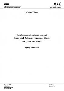
II HIP PROTECTOR SYSTEM As mentioned before, hip fractures account for most of the deaths and costs of falls and fall-induced fractures, especially for elderly people. We propose to develop intelligent and personalized wearable airbags to reduce the force of impact during a fall for elderly. Recent advances in manufacturing technologies have made it possible to safely compress air in small, light weight, and low-cost pressurized cylinders, thereby making a personalized airbag system not only possible but economically feasible. In addition, a MEMS based inertia measurement unit is suitable for small, light weight hip protector system, and can be intelligently programmed to measure and recognize human motions to trigger the inflation of the airbag(s) before a subject falls to the ground. Fig. 1 illustrates the basic concept of an intelligent hip protector system. A micro 3-D motion-sensor based belt is mounted on the waist and is worn by a subject. The motion sensing system will be fully calibrated to compensate for temperature and environmental vibration effects. Two air bags, each with about 4.5” inch inflated diameter are connected by polypropylene tubes to a small compressed air cylinder of volume less than 10 mL, and are embedded in the belt and are positioned on the greater trochanter of each hip. Based on our calculations, these airbags are expected to reduce the impact force during a fall by around 2000N.
tested using the established method in our laboratory. The motion-based condition of activating the inflation process will be defined such that it is sensitive enough to detect imbalance of an elderly but not too hypersensitive to induce false alarm. To test a falling-down condition and generate a trigger signal by the µIMU is the key issue discussed in this paper. Ⅲ
µIMU DESIGN
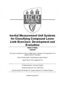
MEMS sensors play a major role in the µIMU due to their low-cost and miniaturized size. We use MEMS sensors to measure the 3D accelerations and 3D angular rates, with the coordinate transformations and filtering calculations performed by a Micro Control Unit (MCU). A. System Description As shown in Fig. 2, the sensor analog signals are first converted into digital signals, before the DFT (Discrete Fourier Test) transform was performed on the signals. Then, the DFT-filtered signals are compared with the SVM data to match the physical data being recorded by the sensors, i.e. if the data matches the SVM data of a falling-motion, then a “1” is generated
(a)
Figure 1. Conceptual illustration of the “Smart Hip Protection” system in action. When an elderly loses balance, the MEMS micro sensors in the belt will detect his/her disorientation and triggers the inflation of the airbag on the side in a few milli-seconds before falling to the ground. The hip-airbags can be designed just like automobile airbags, which contain many micron-size holes for automatic deflation. Therefore, distension can be controlled to last for a few seconds, and the hip-airbags will gradually collapse afterwards. The force attenuation property of the inflated hip protector will be
(b)
Figure 2. Schematic chart of the µIMU. (a) Final system architecture. (b) Prototype system architecture.
to trigger the airbags. The entire µIMU includes mainly two parts: the MEMS sensors and the MCU. We used three gyroscope sensors (single-axis) and two accelerometers (dual-axes) to detect human motion. The raw sensor signal is expressed by analogue
voltages of -2.5v to +2.5v each. The MCU first converts the signals to digital signals, then transmits the packed data signal sequentially via a USB chip and wire to a computer. After hundreds of experiments, which include lateral falling-down, walking, running, sitting and stepping stairs, we formed a database for Support Vector Machines (SVM) training. After training, we selected the best features as SVM filter for falling motion recognition. Then the filter program was loaded into the MCU to perform such a function in real time. B. Hardware An illustration of components of µIMU is shown below in Fig. 3. Three single-axis MEMS gyroscope sensors (ADXRS150 Analog Devices Inc.) are mounted as shown, each can test one angular rate in one direction; thus we can measure yaw, roll and pitch of the body motion. Also, two dual-axis MEMS accelerometers (ADXL311 Analog Devices Inc.) are mounted in the backside of the same PCB boards housing the gyros. The two sensors can detect the acceleration motion of an object in three dimensions.
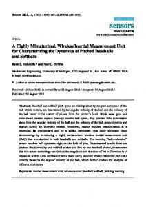
angular rate and acceleration, the minimum value is 0 and the maximum value is 255, that is, 128 is the zero point of angular rates and accelerations. Then the actual value can be obtained by F(x) = (x-128) × K, where for acceleration, K is equal to 1.63m/s, for angular rate, K=1.172 degree/s (calculated from manufacturer’s datasheets). The second part is the data recording and analysis. As Fig. 4 shows, the computer receives all accelerations and angular rates and display in six diagrams in time domain, each represents one axis acceleration or rotation rate. At the same time, a txt file is generated consisting of six characters for DFT filtering and analysis.
Figure 4. Time domain accelerations and rotation rates in 3 axes.
Figure 3. Photograph of a 3-D motion system consisting of 3 gyros and 3 acceleration sensors and a micro processor. The original analog signal generated by the sensors is transmitted directly to the ADC channels of the MCU (AT Mega 8535L) After A/D transform, the digital signal is passed to the USB chip through the TXD port for transmission to PC for off-line analysis. Wireless transmission to the PC will be implemented at a later stage. The MCU supports In-System-Programming to update software. After experiments and Support Vector Machines (SVM) training with the database, we can download new programs for motion recording and falling-down recognition. A micro battery cell will also be added to serve as power supply in the final system. C. Software The software for µIMU mainly includes 3 parts. The first part is C programming for MCU, which transforms the original analogue into digital signal and transmit data package to computer via USB module. We describe our digital signal as follows. For each
The third part is the program integrated with the SVM training features, which on one hand, will still transform analogue signals into digital data, and on the other hand, the features act as a filter. It will judge the information transformed from the sensors, i.e., if the motion is a falling state. If it is a dangerous state, the MCU will send out a signal of 1, indicates that the body is falling down, then the system will trigger the airbags for inflation. Ⅳ SVM TRAINING FOR FALLING-DOWN RECOGNITION Our goal is to recognize falling-motion in real-time in order to control the hip-protecting airbags. We address this classification problem as a binary pattern recognition using Support Vector Machines (SVM): (1) Set up motion database of ‘falling-down’ and ‘non-falling-down’ by experiments wearing the uIMU; (2) Use Supervised PCA (Principle Component Analysis) to generate and select characteristic features; (3) SVM training and finally get the SVM filter. A. Supervised PCA for Feature Selection Feature generation and selection are very important in falling-motion recognition, as badly selected features such as weightlessness, leaning backward, and hip spinning may cause confusion with jumping, sitting and
turning around, which can obviously diminish the performance of the system. Furthermore, even though the present features contain enough information about the output class, they may not predict the output correctly because the dimension of feature space may be so large that it requires numerous instances to determine the result. Principle Component Analysis (PCA) can generate mutually uncorrelated features while packing most of the information in several eigenvectors. It is widely investigated in pattern recognition and in a number of signal and image processing applications. So in our system, we use Supervised PCA (SPCA) algorithms for feature generation and selection. A set of eigenvectors can be computed from the training motion data and some of eigenvectors are selected for classification according to the corresponding eigenvalue. We consider that every feature encodes different information in a certain scale such as moving backward, weightlessness, moving down, etc. We selected the eigenvectors according to the binary classified capability, instead of the corresponding eigenvalues. It is because the eigenvectors with large eigenvalues may carry the common features, but not the distinguishing information between the two classes. The method can be described in brief as follows. Suppose that we have two sets of training samples: A and B. The number of training samples in each set is N. Φi represents each eigenvector produced by PCA. Each of the training samples, including positive samples and negative samples, can be projected into an axis extended by the corresponding eigenvector. By analyzing the distribution of the projected 2N points, we can roughly select the eigenvectors which have more motion information. The following is a detailed description of the process. (1) For a certain eigenvector Φi, compute its mapping result according to the two sets of training samples. The result can be described as λi,j, (1≤i≤M, 1≤j≤2N); (2) Train a classifier fi using a simple method such as Perception or Neural Network which can separate λi,j into two groups: falling-down and non-falling-down with a minimum error E(fi); (3) If, E(fi)